Assignment 1-2D Meshing Challenge
OBJECTIVE: To Carry out the geometry cleanup operation on the given 3 files.
- Practice
- Clip Repair
- Mounting Bracket
There should not be any free edges, convert all of them into refine geometry.
- Clean the geometry.
- Extract midsurface.
- Clean midsurface geometry.
- Ignore holes less than dia 5mm.
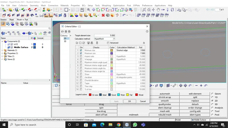
- Create 2D mesh with target length 5mm, min 3.5 mm, max 7 mm.
- And assign proper thickness, by creating a generic property.
MODEL:
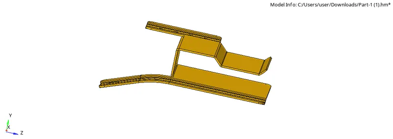
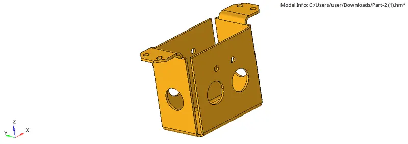
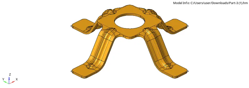
PROCEDURE:Part1
STEP1: Import the model into the graphical user area.
STEP2: Make sure there are no free edges in the model before proceeding for meshing.
STEP3: Perform geometry cleanup on the component such as removing free edges,fixing deformed surfaces.
STEP4: Using quick edit panel perform toggle operation and fix the free edges.
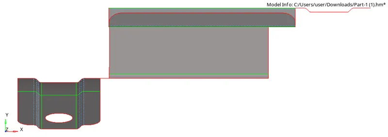
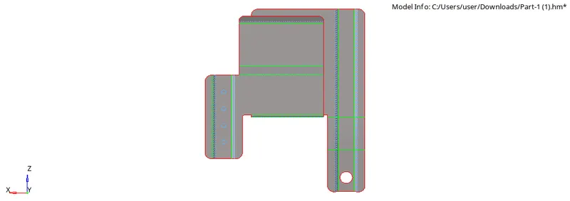
STEP5: After the geometry cleanup is done the next step is to create a midsurface for the Geometry.
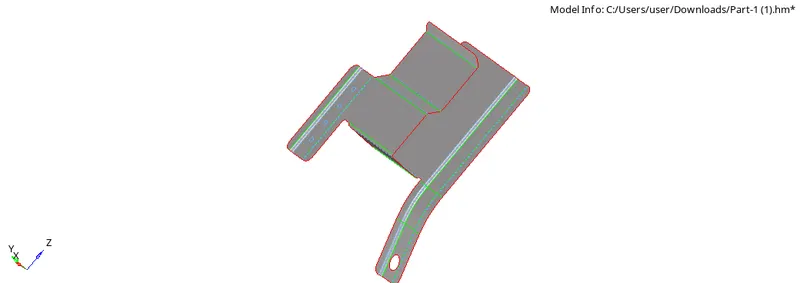
STEP6: Using the automidsurface option or we can use surfce offset tool to create the midsurface to perform meshing.
STEP7: Fill the holes which are less than 5mm in diameter as mentioned in the question.
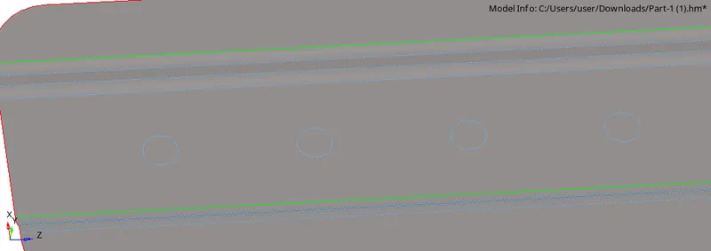
STEP8: Set the required quality criteria in the criteria settings and set the element size.
STEP9: Go to 2d-automesh-set element size as 5mm and select surfaces to mesh.

STEP10: Make sure the mesh flow is proper and avoid opposite trias.
STEP11: Check for the element quality and Make sure the elements are all passed for the quality.
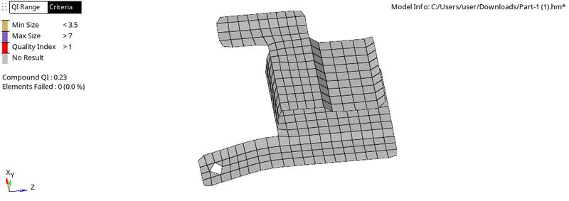
STEP12: Next step, is to check free edges,make sure there is proper connectivity between elements in the given model.
STEP13: If connectivity is missing try to equivalence the nodes by increasing the tolerance or connect manually if the distance to large.
STEP14: We can connect manually by using replace nodes option.
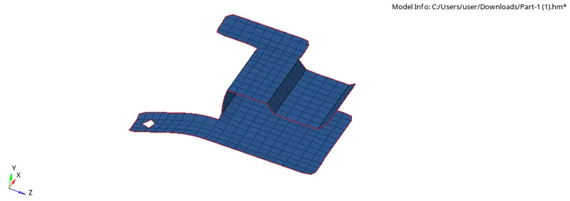
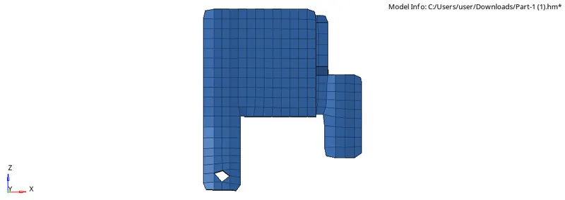
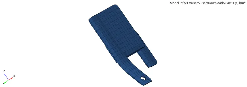
STEP15: The model is meshed with the given element size and quality criteria is achieved and free edges are removed.
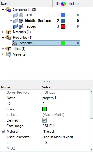
STEP16: Create a property and assign the thickness by measuring the thickness using distance option
STEP17: Assign thickness value in the property tab and assign the property to midsurface
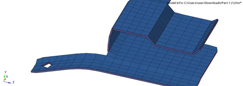
FINAL MODEL IMAGES
PROCEDURE: Part2
STEP1: Import the model into the graphical user area.
STEP2: Make sure there are no free edges in the model before proceeding for meshing.
STEP3: Perform geometry cleanup on the component such as removing free edges,fixing deformed surfaces.
STEP4: Using quick edit panel perform toggle operation and fix the free edges.
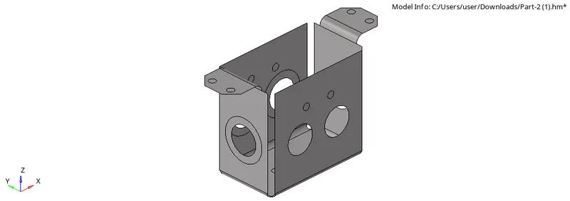
STEP5: After the geometry cleanup is done the next step is to create a midsurface.
STEP6: Using the automidsurface option create the midsurface to perform meshing.
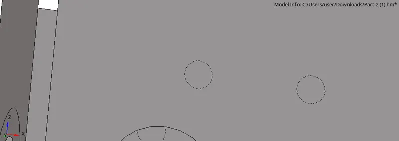
STEP7: Fill the holes which are less than 5mm in diameter as mentioned in the question.
STEP8: Set the required quality criteria in the criteria settings and set the element size.
STEP9: Go to 2d-automesh-set element size as 5mm and select surfaces to mesh.
STEP10: Make sure the mesh flow is proper and avoid opposite trias.
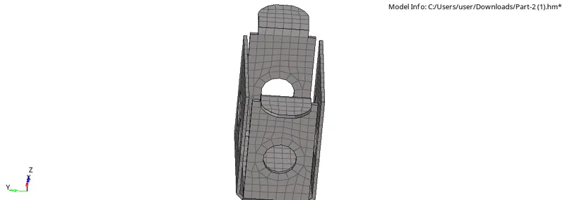
STE11: Use the reflect option to reflect the mesh on other side as there is symmetry in the component.

STEP12:Make sure the elements are all passed for the quality.
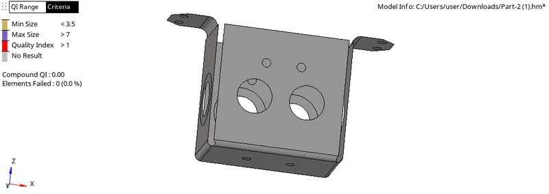
STEP13: Next step, is to check free edges,make sure there is proper connectivity between elements.
STEP14: If connectivity is missing try to equivalence the nodes by increasing the tolerance.
STEP15: Otherwise manually connect it with replace nodes option.
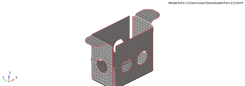
STEP16:The model is meshed with the given element size and quality criteria is achieved and free edges are absent.
STEP17: Create a property and assign the thickness by measuring the thickness using distance option
STEP18: Assign thickness value in the property tab and assign the property to midsurface
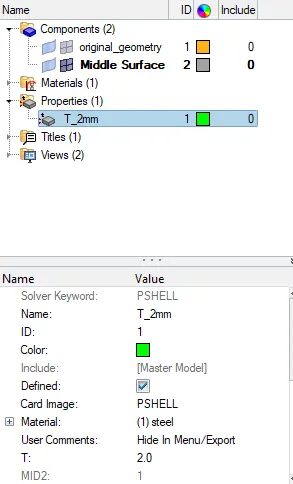
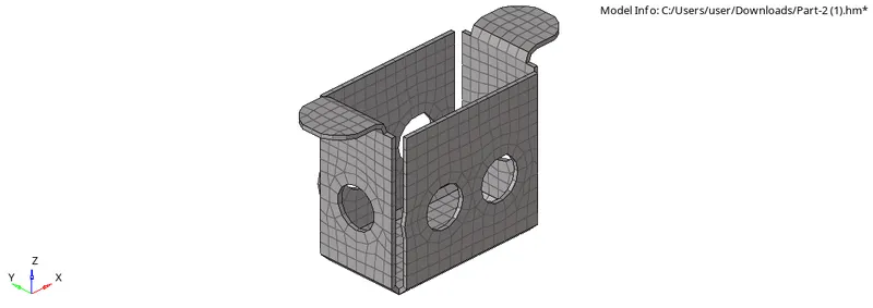
FINAL MODEL IMAGES
ROCEDURE:Part3
STEP1: Import the model into the graphical user area.
STEP2: Make sure there are no free edges in the model before proceeding for meshing.
STEP3: Perform geometry cleanup on the component such as removing free edges,fixing deformed surfaces.
STEP4: Using quick edit panel perform toggle operation and fix the free edges.
STEP5: After the geometry cleanup is done the next step is to create a midsurface.
STEP6: Using the automidsurface option create the midsurface to perform meshing.
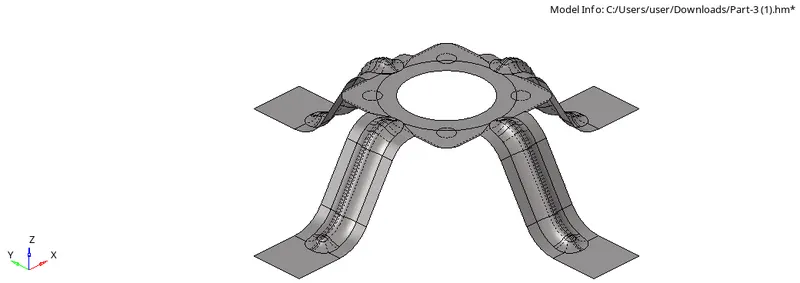
STEP7: Fill the holes which are less than 5mm in diameter as mentioned in the question and clean the geometry at the fillets to avoid minimum length failure.
STEP8: Set the required quality criteria in the criteria settings and set the element size.
STEP9: Go to 2d-automesh-set element size as 5mm and select surfaces to mesh.
STEP10: Make sure the mesh flow is proper and avoid opposite trias.
STEP11: Make sure the elements are all passed for the quality.
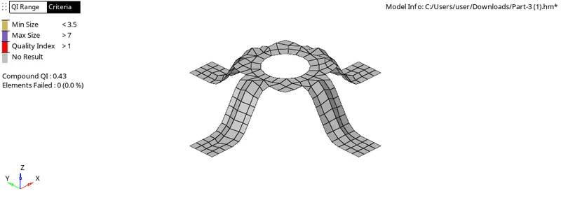
STEP12: Make sure all the features are captured accordingly.
STEP13: Next step, is to check free edges,make sure there is proper connectivity between elements.
STEP14: If connectivity is missing try to equivalence the nodes by increasing the tolerance.
STEP15: Otherwise manually connect it with replace nodes option.
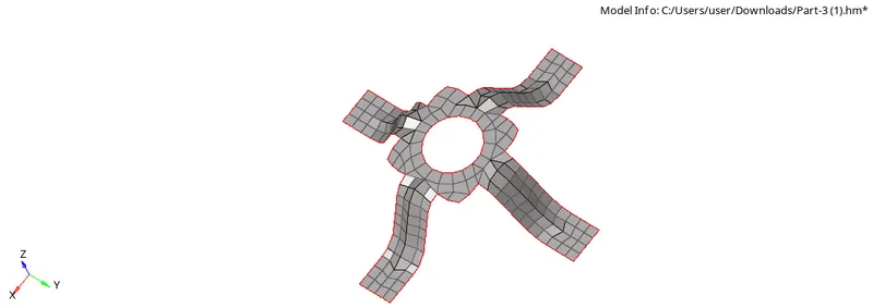
STEP16:The model is meshed with the given element size and quality criteria is achieved and free edges are absent.
STEP17: Create a property and assign the thickness by measuring the thickness using distance option
STEP18: Assign thickness value in the property tab and assign the property to midsurface
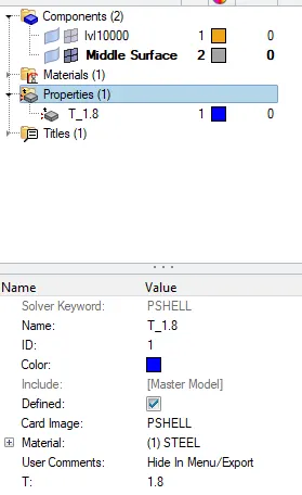
FINAL MODEL IMAGES
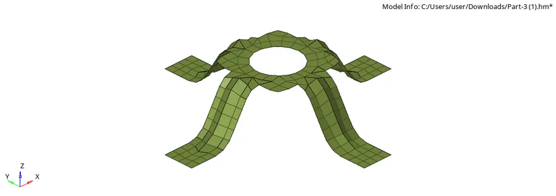
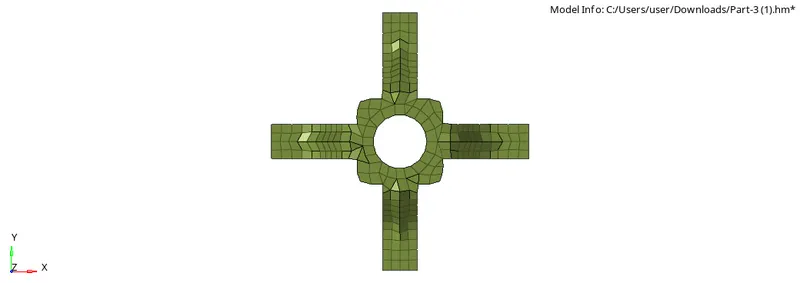
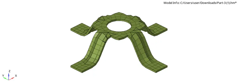
CONCLUSION:
There should not be any free edges, convert all of them into refine geometry.
- Clean the geometry.
- Extract midsurface.
- Clean midsurface geometry.
- Ignore holes less than dia 5mm.
- Create 2D mesh with target length 5mm, min 3.5mm max 7mm.
- And assign proper thickness, by creating a generic property.