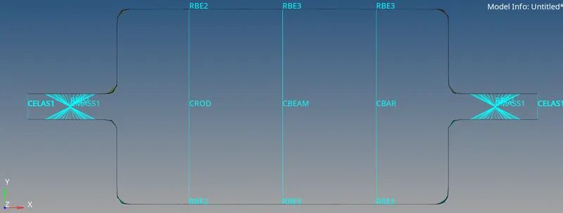
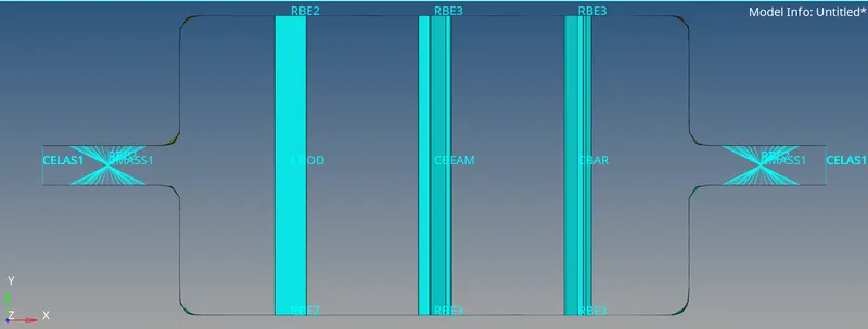
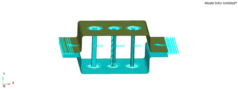
1D Element Creation
Question:-
Mesh the Given component with the Size of 5 Units. Create 1D elements on the following component with given cross-section and DOF.
a. Rod element:- Translational DOF should be Constrained with RBE2 link
Cross-Section: BOX- Dimension a= 12 mm
dimension b=10 mm
Thickness t= 0.75 mm
b. Beam element:- All DOF should be constrained with RBE3 link
Cross-Section: I Section- Dimension a= 8 mm
Dimension b= 10 mm
Dimension c= 8.5 mm
Thickness t1= 0.75 mm
Thickness t2= .6 mm
Thickness t3= .6 mm
c. Bar element:- Constrain only x and y DOFs With RBE3 link
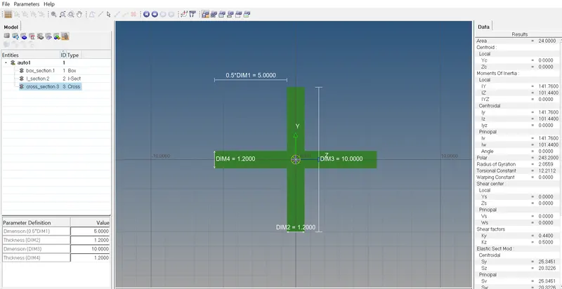
Cross-section: X section- Dimension DIM1= 5 mm
Thickness DIM2= 1.2 mm
Dimension DIM3= 10 mm
Thickness DIM4= 1.2mm
d. & e. Apply the mass of magnitude 10 with the RBE2 link
f. Join the two components with Spring elements.
Objective:-
The main objective is to create mesh on the given component and to create 1D elements on the following component with given cross-section and DOF.
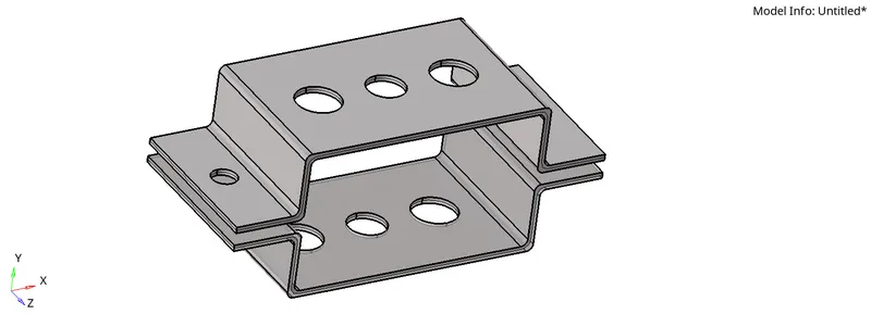
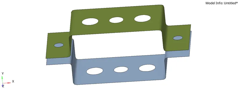
CAD model image:-
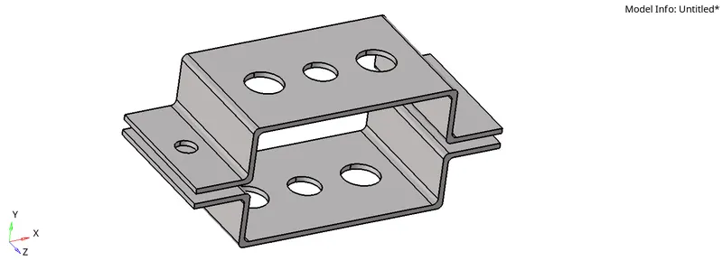
Procedure:-
Step-1:-
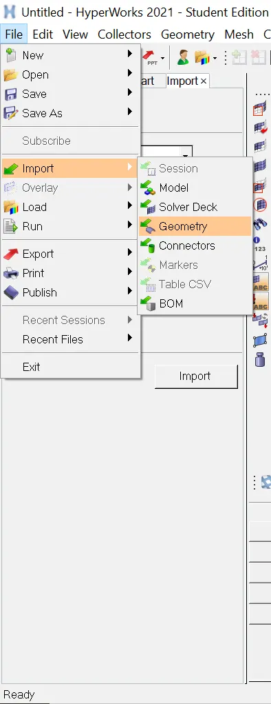
Importing of CAD model:-First we need to import the CAD model in to the Hyperworks software.
- File
- Import
- Geometry
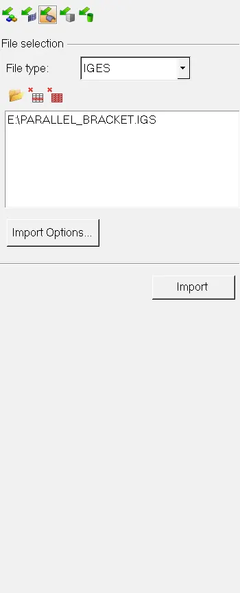
Then we need to select the file type as IGES format and select the file and click on the import.
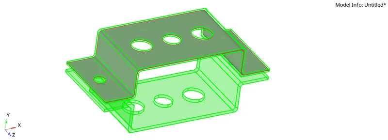
File will be imported to the Hyperworks software.
Step-2:-
Creating midsurfaces:-Now go to the Geometry tool and click on the midsurfaces then select the surface and click extract.
- Geometry tool
- midsurfaces
- surface
- extract
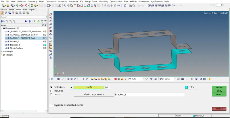
Now create a new compoment as Bracket_2 and repeat the same on the other side of the bracket then click on the return.
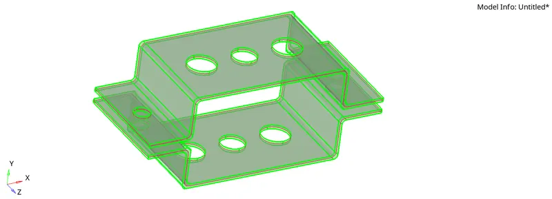
Here we can see the midsurfaces are created.
Step-3:-
Deleting solids:-We need to select delete option for deleting the solids then go to the solids and select displayed and click on the delete entity.
- Delete
- solids
- displayed
- delete entity
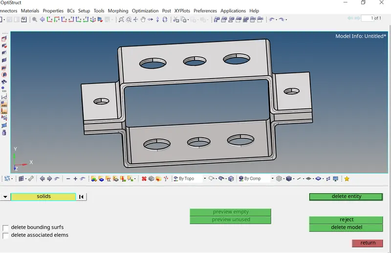
We need to assign the second midsurface to the Bracket_2 in the tools go to organize and select surfaces and click on move.
- tool
- organize
- surface
- move
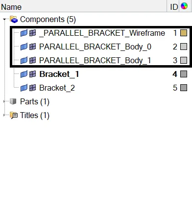
Delete the unwanted components.
Step-4:-
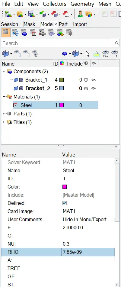
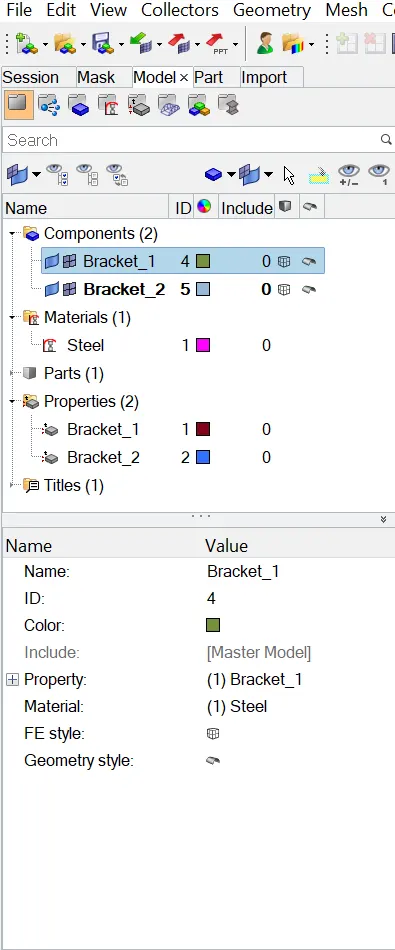
Create material:-We need to create materal as steel and select Card image as MAT1 for steel and select young's modulus(E),poisson's ratio(NU),density(roh).
- Create
- material
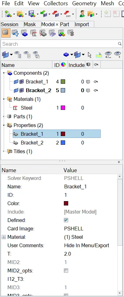
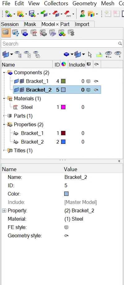
Create property:-Create two properties one as Bracket_1 and another as a Bracket_2 give card image as a PSHELL for both the properties and add material as steel and give thickness for Bracket_1 as 2.0 and for Bracket_2 as 2.5.
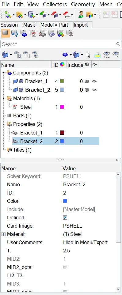
Add property and material:-We need to add property and material to the both Bracket_1 and Bracket_2.
Step-5:-
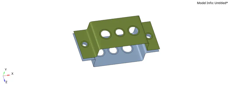
Providing washer splits:-We need to provide washer splits at the holes in the model by clicking on the geometry tool then go to quick edit then washer splits select lines and give offset value as 5.
- Geometry tools
- quick edit
- washer splits
- lines
Step-6:-
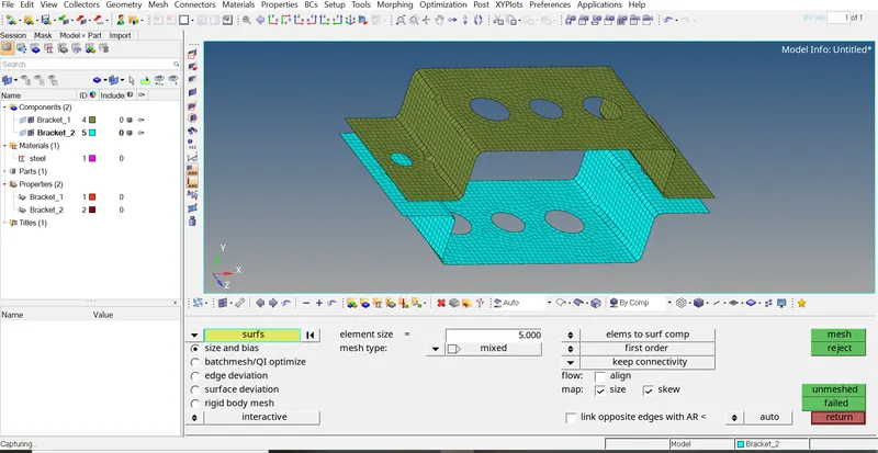
2D Meshing:-For 2D mesh go to the 2D then select automesh select element size as 5 and select mesh type as mixed and select all the surfaces and click on the mesh
- 2D
- automesh
- element size
- mesh type
- surfaces
- all
- mesh
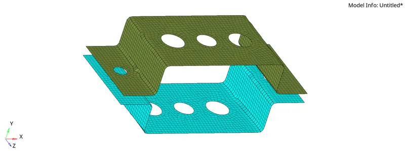
Step-7:-
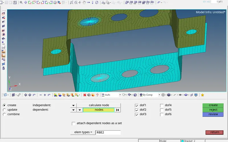
Creating RBE2 link(rigids) at location (a):-For Creating RBE2 link at the location a go to 1D then click on the rigids then click on the node multiple nodes,calculate node and select nodes by path at the location a and constrain translational DOF, To constrain translational DOF we need to uncheck the dof4,dof5,dof6 then click on the create.
- 1D
- rigids
- node
- multiple nodes
- calculate node
- nodes by path
- create
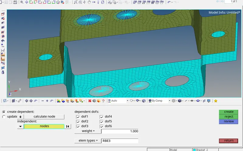
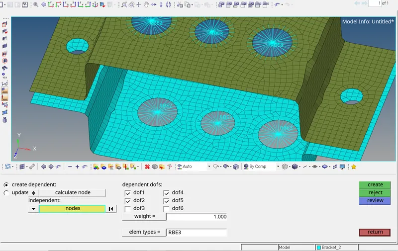
Creating RBE3 links at location (b&c):-For Creating RBE3 link at the location b&c go to 1D then click on the rbe3 then click on the nodes and select nodes by path at the location b&c and constrain all DOF at location b and constrain X and Y DOF's at location c, To constrain translational DOF we need to uncheck the dof4,dof5,dof6 then click on the create.
- 1D
- rbe3
- nodes
- nodes by path
- create
At location b:-
At location c:-
Step-8:-
Creating Box,I section & X section:-To create Box,I,X sections of required dimension first go to 1D and select Hyperbeam then go to standard section in standard section library select hyperbeam and in standard section type select Box,I or X section and give required dimensions.
- 1D
- Hyperbeam
- standard section
- standard section library
- hyperbeam
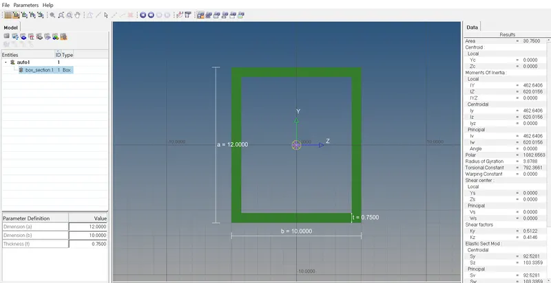
Creating Box:-In the standard section type select thinwalled box and click on create,then give dimensions as a=12 mm,b=10 mm,t=0.75 mm.
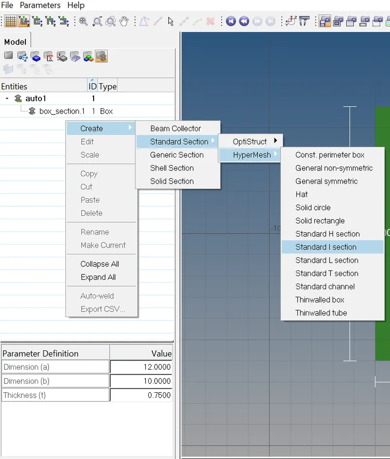
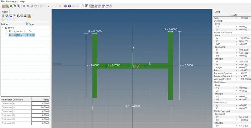
Creating I section:-In the hyperbeam view click on create-standard section-Hypermesh-standard I section and give dimensions as a=8 mm,b=10 mm,c=8.5 mm,t1=0.75 mm,t2=0.6 mm,t3=0.6 mm.
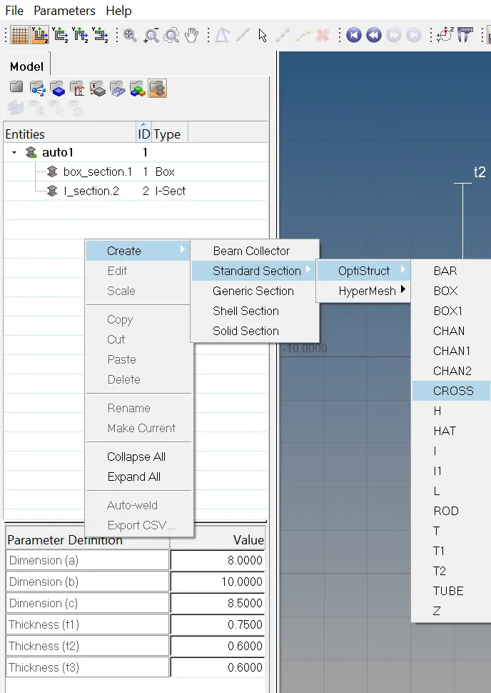
Creating X section:-In the hyperbeam view click on create-Standard section-Optistruct-CROSS and give dimensions as DIM1= 5 mm,DIM2= 1.2 mm,DIM3= 10 mm,DIM4= 1.2mm.
Step-9:-
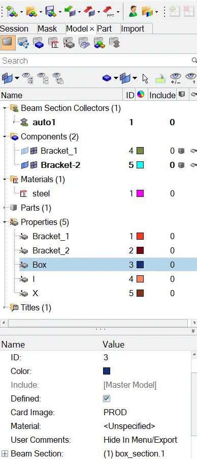
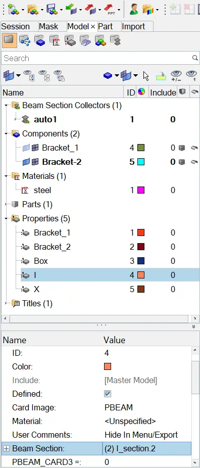
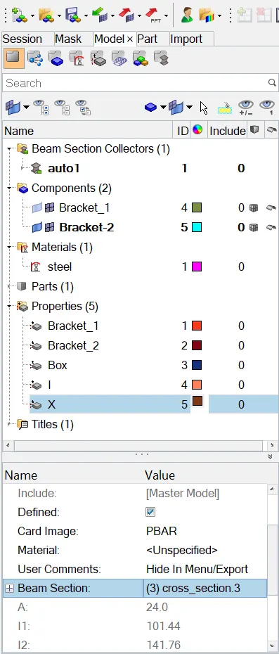
Creating property for Box,I,X sections:-Now go to create and create a 3 new properties as Box,I,X Sections.
Box:-In the Box property give Card image as PROD and Beam section as box_section.
I section property:-In the I section property give Card image as PBEAM and Beam section as I_section.
X section property:-In the X section property give Card image as PBAR and Beam section as cross_section.
Step-10:-
Creating Rod,Beam,Bar elements:-
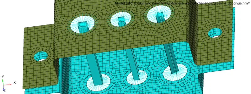
Rod element at location a:-To create Rod element at location a go to 1D and select rods and select independent nodes at both sides of the RBE2 link and select element type as CROD and click on create.Then go to Property and select property as Box.
- 1D
- rods
- element type
- CROD
- create
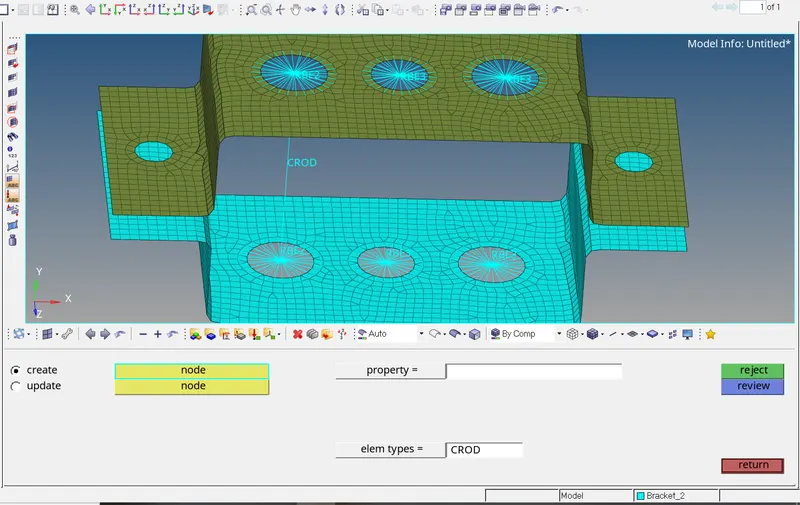
Beam element at location b:-To create beam element at location b go to 1D and select bars and independent node on both sides and give direction of vector on the RBE3 link and select element type as CBEAM then go to the property and select property as I.
- 1D
- bars
- element type
- CBEAM
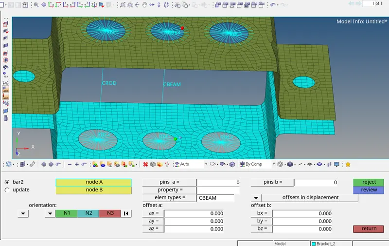
Bar element at location c:-To create bar element at location c at first go to 1D select bars and independent node on both sides and give direction of vector on the RBE3 link and select element type as CBAR then go to the property and select property as X.
- 1D
- bars
- element type
- CBAR
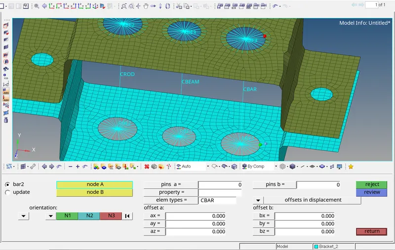
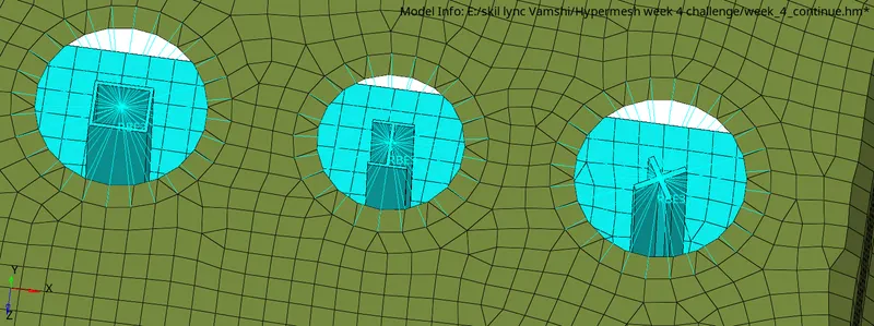
After assigning all the properties click on the 1D detailed element representation.
Step-11:-
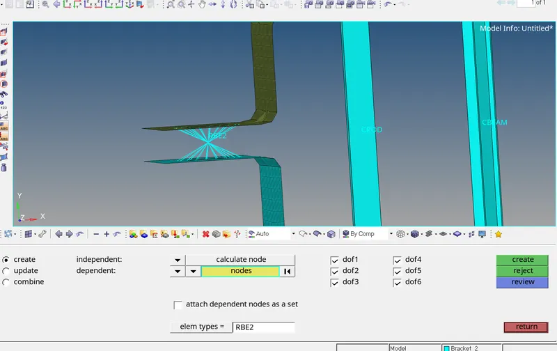
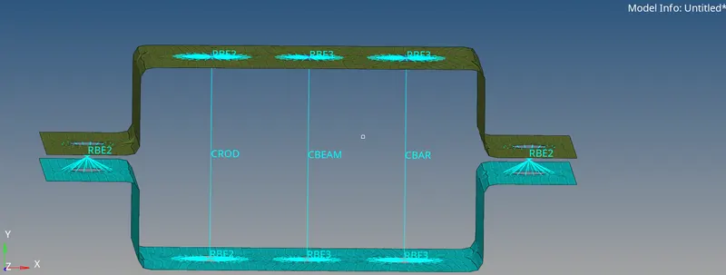
Applying the mass of magnitude 10 with RBE2 link at d & e:-For Creating RBE2 link at the location d & e go to 1D then click on the rigids then click on the node multiple nodes,calculate node and select nodes by path at the location d & e then click on create RBE2 links are created.
- 1D
- rigids
- node
- multiple nodes
- calculate node
- nodes by path
- create
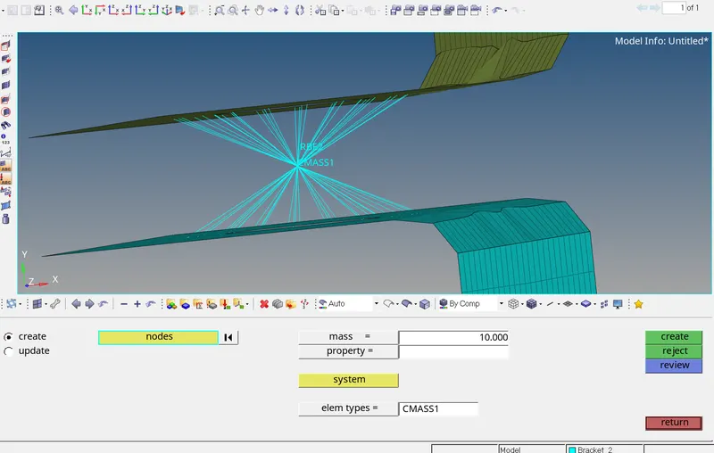
Then go to masses and select independent node give mass as 10 and select element type as CMASS1 and click on create.
- 1D
- masses
- element type
- CMASS1
- create
Step-12:-
Creating spring elements:-Now we need to create spring elements to Join the two components,Go to 1D-Springs select nodes and select element type as CELAS1.
- 1D
- springs
- element type
- CELAS1
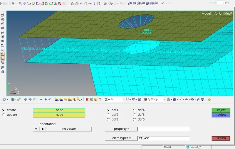
Result:-Given component is meshed and 1D elements are created on the following component with given cross-section and DOF.
Final Model image:-