Assignment 1-2D Meshing Challenge
MESHING
Finite element analysis (FEA) is a mathematical representation of a physical system comprising a part/assembly, material properties, and boundary conditions. In several situations, product behavior in the real world cannot be approximated by simple hand calculations. A general technique like FEA is a convenient method to represent complex behaviors by accurately capturing physical phenomena using partial differential equations. FEA has matured and has been democratized so that it can be used both by design engineers and specialists.
Meshing is one of the most important steps in performing an accurate simulation using FEA. A mesh is made up of elements that contain nodes (coordinate locations in space that can vary by element type) that represent the shape of the geometry. An FEA solver cannot easily work with irregular shapes, but it is much happier with common shapes like cubes. Meshing is the process of turning irregular shapes into more recognizable volumes called “elements.
Simply put, a good quality mesh equals more precise results. A poor mesh can result in convergence difficulties, which can lead to incorrect results and false conclusions. The quality of your mesh depends on a few scenarios:
- What type of analysis you are conducting.
- How much time do you want to invest in the mesh?
- How much time do you want to invest in solving?
In some instances, you may be looking for a quick solution — something that will help clarify a design decision. In this instance, you may not want to spend a lot of time setting up your mesh. Other times, you may want a very precise solution or result, which would require some time and effort into setting up your mesh with different methods and controls.
A good mesh has a quality criterion that fits your needs (analysis type, level of accuracy, time) such as element quality and aspect ratio. Ultimately, we recommend understanding your geometry and using controls to get the best mesh possible — which, after all, leads to a better product design.
Geometry Cleanup Exercise:
Carry out the geometry cleanup operation on the given 3 files.
- Practice
- Clip Repair
- Mounting Bracket
There should not be any free edges, convert all of them into refined geometry.
- Clean the geometry.
- Extract mid surface.
- Clean mid-surface geometry.
- Ignore holes less than dia 5mm.
- Create a 2D mesh with target length 5mm, min 3.5mm max 7mm.
- And assign proper thickness, by creating a generic property.
Answer
CAD models
Part 1
Mounting bracket
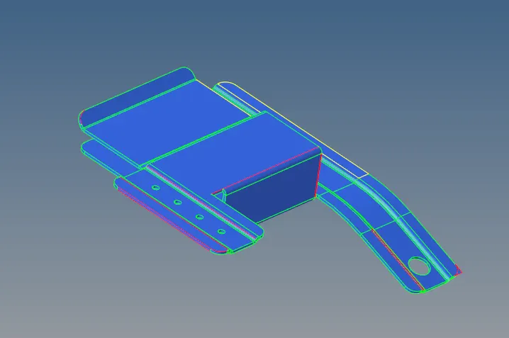
Part 2
Practice
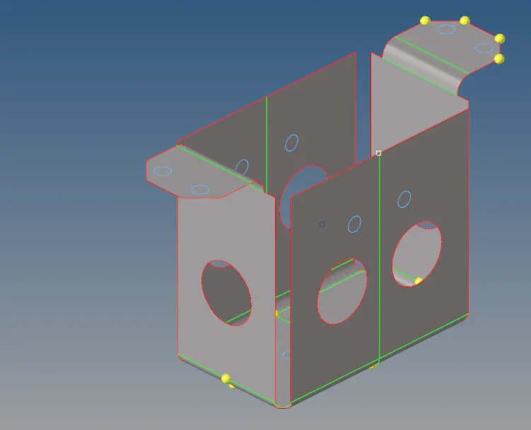
Part 3
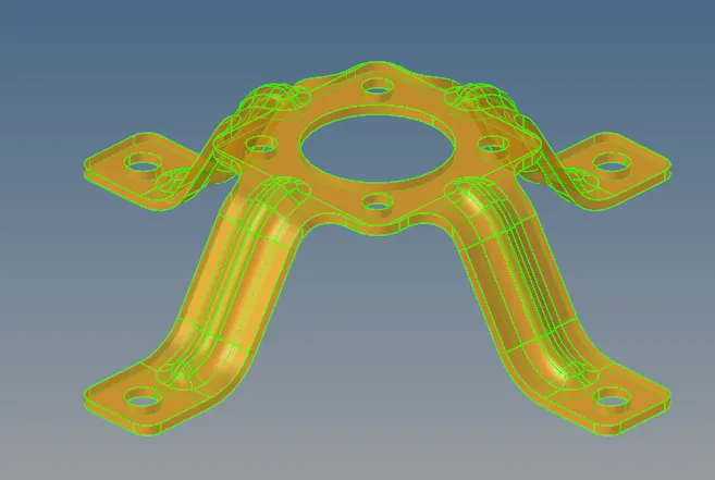
Clip repair
Procedure
1. First we Import the 3d model into hypermesh
2. Then we need to perform Geometry cleanup
Usually, when we import such cad models, it's not rare to have some geometrical errors in the model which we need to fix to a point where the original geometry doesn't change
Some of the main things used to clean up the geometry were :
Filler surface
toggle surface
trim edge
replace points
delete surfaces
all of which can be found in the Geom tab, quick edit section.

3. After Geomery cleanup, we make sure that there aren't any imperfections and head on to create the mid surface. This too can be found in the Geom tab.
Usually, with uniform thickness cad models, we create a mid surface and then offset the mesh elements to complete the meshing process.
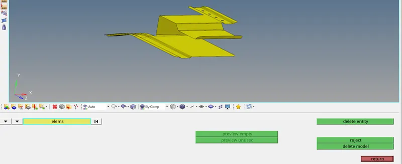
4. Once we create a mid surface, we make the mid surface the current model we will be working on.
Midsurface tab :

5. Then in the 2d tab, we select the auto mesh option and select the mid surface.
2d tab :

Auto mesh tab :

6. The software will create a basic mesh with basic parameters, usually, the element size will be automatically calculated, but since the target length of the mesh is 5mm, we change it.
7. Now, we can change the mesh according to the criteria given. In the 2d tab, we use the rebuild mesh command to change the mesh settings. The criteria for meshing such as aspect ratio, minimum and maximum element length, etc. can be edited and remeshed, And also the parameters for meshing can be controlled.
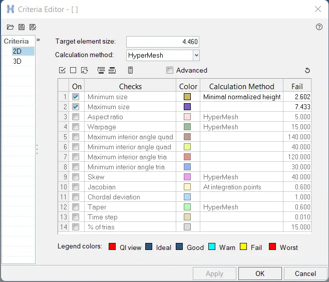
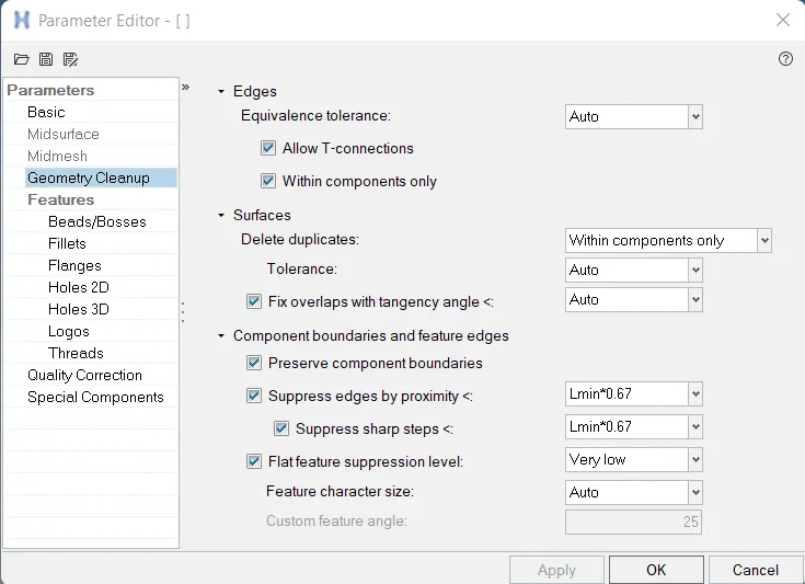
7. Before we Use the Auto mesh command, we need to check other criteria for meshing. holes having diameters less than 5mm will be considered as a surface and not a hole. So we use the filler material command and then toggle the edges so that the mesher doesn't consider that as a feature.
8. Then we perform a check on the remeshed elements to see if they meet the criteria given.

9. Then we implement thickness by assigning a generic property.
The Final meshed parts are given below
Part 1

Part 2
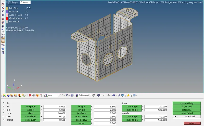
Part 3
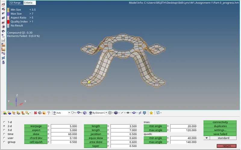
With the element checks done, there are no issues with the meshing. The Thickness assigned was 1.8mm for all the 3 parts.