Assignment 1
AIM:
To extract midsumesh surface and create a mesh on the given component.
PROCEDURE:
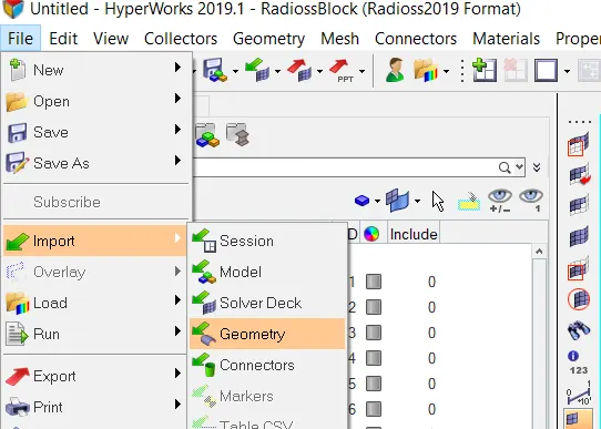
- Import the given component into the hypermesh.
- Geometry cleanup the given component by using the options in quick edit panel etc.
- Then extract the midsurface of the given components by using auto midsurface option.
- There is a manual midsurface option in the surface edit panel.
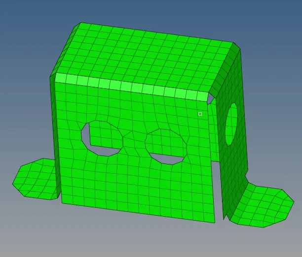
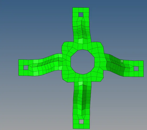
- After extracting midsurface, meshing the components with the auto mesh option in 2d panel.
- In meshing reduce trias making proper flow .
- check the elements of the component after meshing within the parameter or not and make it proper.
STEP 1: IMPORT THE MODEL
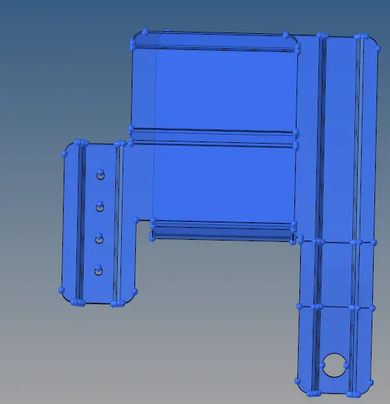
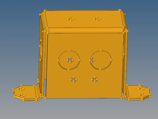
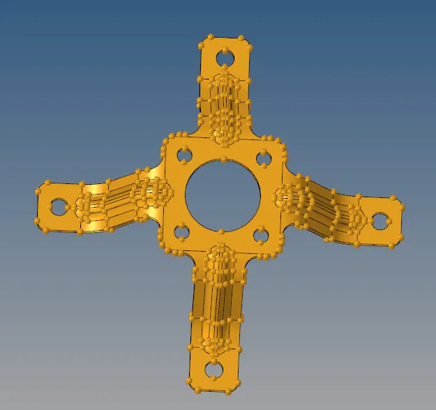
CAD MODEL IMAGE:
STEP 2: GEOMETRY CLEANUP
GEOMETRY > QUICK EDIT
This option is used for geometry cleanup the components . Toggle option is used to correct the line and remove the
unwanted line then the filler surface is used to filling the surface that don't have surface.Replace point is used to join the
lines by point to make it proper. add/remove points are used to add and remove points on the surface.Washer split is used
to make a washer around a hole.Split surf node and node are used to make a line on the surface by using nodes and lines.

GEOMETRY > SURFACE EDIT
In this panel, trim option are used to make a surface seperate by using nodes, lines, surface. After trimming the surface
delete the unwanted surface.

Using this delete option to delete unwanted lines in the components.

GEOMETRY > DISTANCE
This option is used to measure a distance of the surface by using nodes and points. Also used to make a points in
the middle.

2D > REPLACE
This option is used to replace the elements on the line by using nodes and make it proper with the construction lines.

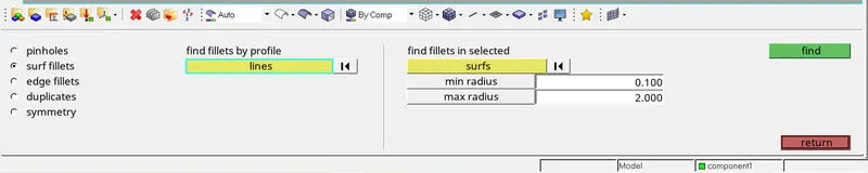
GEOMETRY > DEFEATURE
This option is used to remove the surface fillets and edge fillets that fillets are distrubed the mesh quality for that we
remove the fillets in edge and surface.
STEP 3: EXTRACT MIDSURFACE
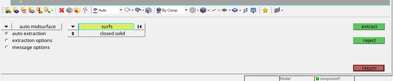
2D > AUTO MIDSURFACE
This option is used to made a midsurface automatically by selecting the surface.
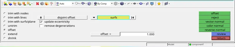
GEOMETRY > SURFACE EDIT
This option is used to make a midsurface manually. First measure the distance between the surface and give the
value to offset by select the top surace or bottom surface then make it duplicate in a seperate compoenet.If the auto
midsurface option give more error then we go with manual midsurface by using offset option.
STEP 4: MESHING OPTION
2D > AUTOMESH
This option is used to mesh the component by selecting the surface.After surface meshing if the mesh flow is not
good then change it into element option and remesh the surface.

STEP 5: CHECK ELEMENTS
After meshing the components, check the element quality by using this option.

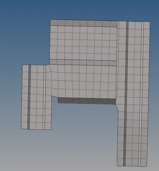
FINAL MODEL IMAGE:
CONCLUSION:
- Understood the basic tools in the hypermesh.
- Understood how to take midsurface.
- Understood how to mesh the component and make a proper flow.
- Understood how to check quality error in the mesh .
RESULT:
Extract midsurface and create mesh on the given components are completed.