Assembly of Yacht
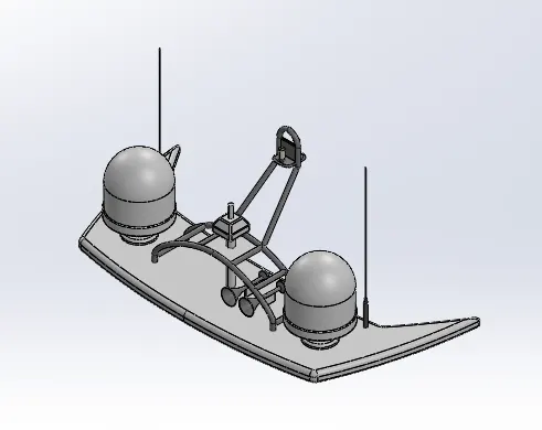
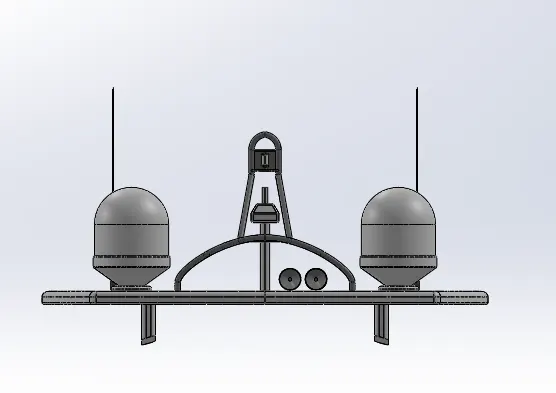
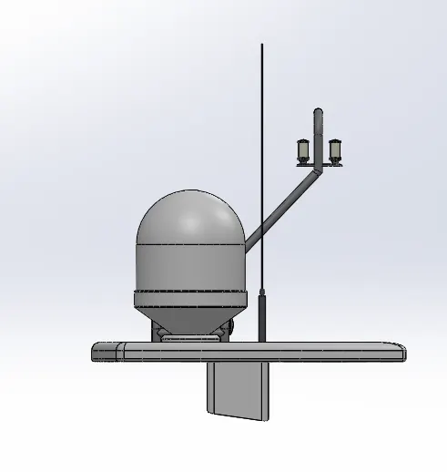
1.RADAR MAST
2.YACHT ASSEMBLY
3.REPORT
MODELING OF YACHT USING SOLIDWORKS
OBJECTIVES:
Main objective of this project is to create model of different parts of YACHT using SOLIDWORKS.
To assemble the different parts modeled for the YACHT.
To create render model using SOLIDWORKS Photo-VIEW 360 and visualize .
PART MODELING:
Modeling means creating virtual prototype of item. In part modeling the build part with some graphical visualization.
FEATURE DISCRIPTION:
SKETCH:
Sketch is the two dimensional representation of a model w.r.t plane/view from the outside of the model. In solidworks different type of sketch option available like Line,Arc,Spline,Circle,Rectangle.
OFFSET:
One or more sketch entities, selected model edges, or model faces by specified distance.
FILLET:
Fillet creates a rounded internal or external face and edges of the parts. You can fillet all edges of face, slected sets of faces, selected edges, or edge loops.
EXTRUDE BOSS/BASS:
Extrude is a type of feature available to convert 2D sketch into the 3D model.
LOFTED BOSS/BASS:
Loft feature allows you to generate complex geometry in a single feature, It does this by interpolating surfaces between various c/s of model. These c/s can be sketches, faces, or edges. In the loft interface, these c/s are considered Lofted Profiles.
DOME:
Select one or more planar or non-planar faces. You can apply dome to faces whose centroid lies outside the face. This allows you to apply domes to irregular shaped counters.
EXTRUDE CUT:
Extrude cut is a another cool feature which helps to remove material from the 3D model. It cuts a sketch profile while extruding, this feature just opposite to extrude boss. Mainly used for creating holes, channels, slots etc.
SPLIT:
The split tool is used to project entites (sketch, solid, surface, face, plane, or surface spline) onto other surfaces or curved/planar faces. You are also able to split faces on multiple bodies with one command.
TRIM ENTITIES:
Select the trim type based on the entities you want to trim or extend. All trim types are available with 2D sketches and 2D sketches on 3D planes. You can use any of the following trim option:Power trim.
REVOLVE:
To create a revolve feature:Create a sketch that contains one or more profiles and a centreline, line or edge to use as a axis of rotation around which the feature revolve.
DYNAMIC MIRRIOR:
Dynamic mirror is important tool which is used to mirror the sketch entities.
APPEARANCES:
An appearance defines the visual properties of model,including colour and texture. Appearances do not affect physical properties, which are defined by materials. Every material is assigned a default appearance that emulates the look of the material.
SHELL:
The shell definition property manager is used to define the thickness of thin and thick shell elements.
CHAMPER:
A cut on the edge of something that makes it slope slightly rather than being perfectly square.
CIRCULAR PATTERN:
The circular parent bodies/feature are used to create a different number of instance required to create the pattern circularly.
LINEAR PATTERN:
The liner parent bodies/features are used to create a different no.of instances required to create the pattern circularly.
SURFACE MODELING:
Surface modeling gives you the ability to build out a visual representation of an objects exterior and its counter.
FEATURE DESCRIPTION:
LOFTED SURFACE:
Lofted surface are surface generated by multiple 3D curves or existing edges creating a smooth tangency between the selected curves.
SWEPT SURFACE:
Sweep surfaces are surfaces that are generated from a section curve positioned along path.
FILLED SURFACE:
The filled surface feature construct a surface patch with any number of sides, within a boundary by existing model edges, sketches or curves, including composite curves.
SURFACE TRIM:
Primarily used to cut away material from a surface, and provides two mode: Standard and Mutual.
EXTENDED SURFACE:
Extended surfaces is used to extend the surfaces which is already created. There are different options available on the extended surface. We can extend the surface as same surface or we can extend the surface tangent to the surface.
SURFACE KNIT:
Surface knit is used to knit the two free edge/open edge of the surfaces together. Alos it reduces the gap between the two edges of the surface.
RULED SURFACE:
Ruled surface command creates surfaces that extend out in a specified direction from selected edges.
TRIM SURFACE:
We can use a surface, plane, or sketch as a trim tool to trim intersecting surfaces. You can also use a surface in conjunction with additional surfaces, as mutual trim tools.
DELETE FACE :
Delete : Deletes a face from a surface body, or deletes one or more faces from a solid body to create surfaces.Using this we can do the following:
Delete and Patch: Deletes a face from a surface body or solid body and automatically patches and trims the body.
Delete and Fill : Deletes faces and generates a single face to close any gap.
PARTS MODELED FOR YACHT:
Propeller
Radar
Hull
Garage door
Front seat
Middle seat
Rare seat
Superstructure
Radar mast
DESCRIPTION OF THE PARTS AND FEATURE USED:
- PROPELLER:
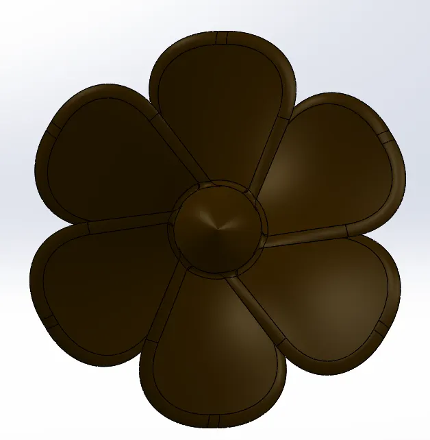
A propeller is a rotating fan-like structure which is used to propel the ship by using the power generated and transmitted by the main engine of the ship. The transmitted power is converted from rotational motion to generate a thrust which imparts momentum to the water, resulting in a force that acts on the ship and pushes it forward.
FEATURES USED:
Revolved boss
Lofted boss
Fillet
Cut extrude
Pattern /Mirror: Circular pattern
- RADAR:
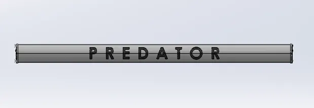
Radar is used to identifying, tracking ship.
FEATURES USED:
Boss extrude
Fillet
Offset entities
Cut extrude
Pattern/Mirror: Sketch driven pattern
Mirror
Text
Split line
- HULL:
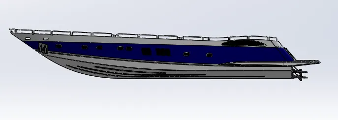
The hull of a ship is the most notable structural entity of the ship. To define the hull, it can be said that it is the watertight enclosure of the ship, which protects the cargo, machinery, and accommodation spaces of the ship from the weather, flooding, and structural damage.
FEATURES USED:
Projected curve
Lofted Surface
Trim surface
Surface Extrude
Knit Surface
Filled Surface
Shell
Trim Entities
Boss Extrude
Cut Extrude
Fillet
Chamfer
Linear pattern
Convert Entities
Swept Boss
Delete Face
Revolved Boss
Dome
Mirror
- GARAGE DOOR:
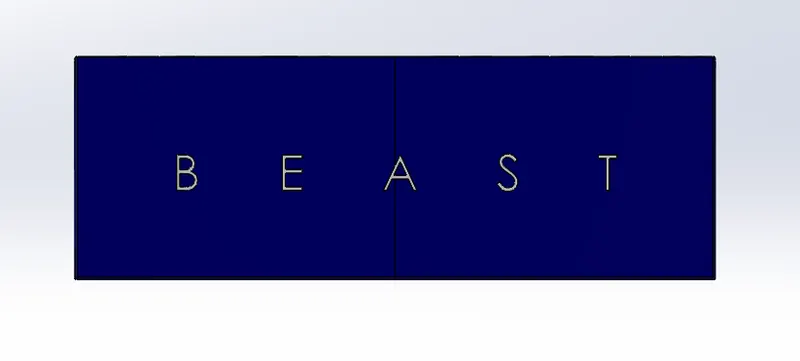
FEATURE USED:
Bass Extrude
Cut Extrude
Fillet
Mirror
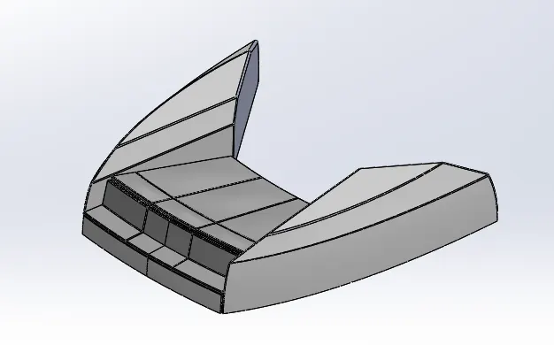
- FRONT SEAT:
Seats are used to sit comfortably .
FEATURES USED:
Swept Surface
Surface Extrude
Trim Surface
Surface Fill
Lofted Surface
Surface Knit
Chamfer
Fillet
Dome
Revolved Boss
Cut Extrude
Mirror
- MIDDLE SEAT:
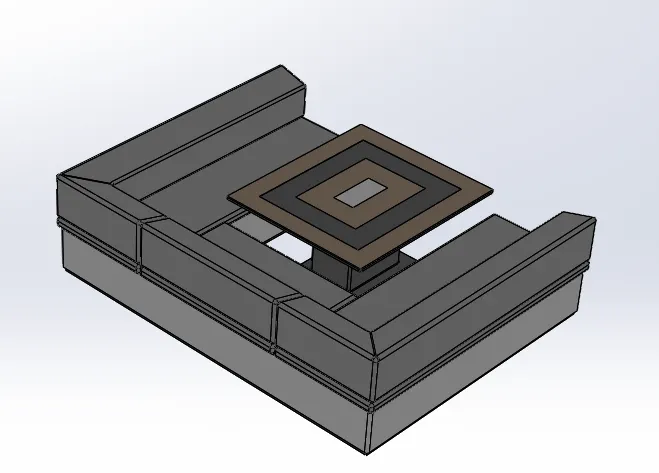
FEATURES USED
Boss Extrude
Cut Extrude
Chamfer
Fillet
Mirror
- REAR SEAT:
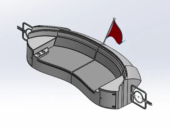
FEATURES USED:
Swept Surface
Offset Surface
Trim Surface
Ruled Surface
Knit Surface
Surface Extend
Extrude Surface
Lofted Surface
Boss Extrude
Cut Extrude
Chamfer
Fillet
Mirror
- SUPER STRUCTURE
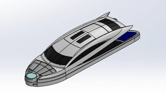
The size of the superstructure has a great influence on the mobility of the vessels. They are designed in a manner, so that, they add value and hinder the speed and mobility in the least. The superstructure is mostly designed in fashion as well. This is because it is the most easily visible part of the ship, in fact it is the identification of the ship, and so the designers try to provide it with the identity that is unique.
FEATURES USED:
Extrude Surface
Swept Surface
Ruled Surface
Trim Surface
Projected curve
Lofted Surface
Filled Surface
Extend Surface
Knit Surface
Boss Extrude
Cut Extrude
Fillet
Chamfer
Dome
Swept Boss
Mirror
- RADAR MAST:
Radar mast is used to mount radar.
FEATURES USED:
Boss Extrude
Revolved Boss
Swept Boss
Pattern mirror
Projected curve
Cut extrude
Chamfer
Fillet
Dome
Mirror
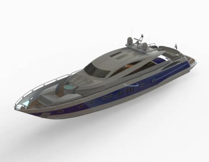
ASSEMBLY OF YACHT:
MAIN ASSEMBLY:
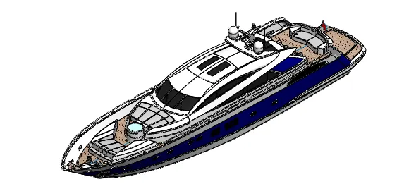
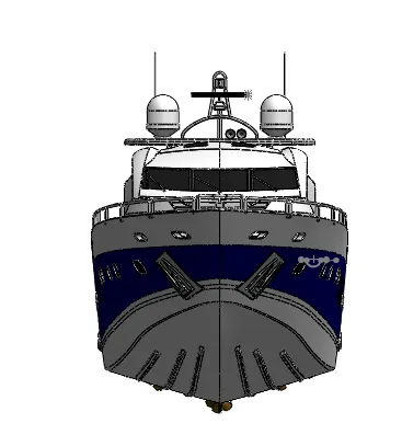
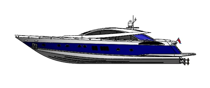
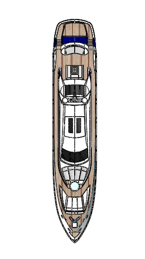
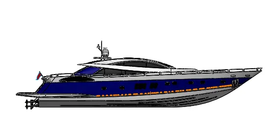
Initially hull part is inserted in the assembly by using insert option. After parts is inserted in the assembly environment and clicked ok to fix the hull.
After that add other parts in assembly environment w.r.t hull using mate condition.
FEATURES USED :
Mates
Insert parts
Mates:
Mates create geometric relationship between assembly components. As we add mates, we define the allowable direction of linear or rotational motion of the component. we can move a component within its degrees of freedom, visualizing the assembly behavior.
Insert Part:
We can insert the other components which need to be mated with the prime fixed component.
RENDERING:
- Rendering is the process of creating realistic images of the photorealistic model with the environment.
- Rendering has been done in two ways in solidworks. The following are the two ways.
Photo view 360
Solidwork Visualize
- In the Photo-realistic model some of the mate condition and positions are changed to render realistic models.
- Then the phot-realistic model is render into realistic image with different views
- Here i have used both the photo-view 360 and and visualise for rendering the assembled model.
CONCLUSION:
- The parts of YACHT are sketched and modeled in the SOLIDWORKS
- The parts are inserted in to assembly environment and YACHT is assembled.
- The photo-realastic image was rendered with the use of the photoview 360 and Solidworks Visualise.
I would like to thanks t my mentor Mr. Soundar Rajan for constant support and guidance which was of great help to complete project successfully.