Assembly of Yacht
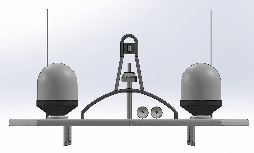
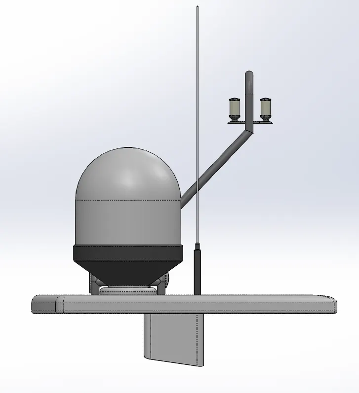
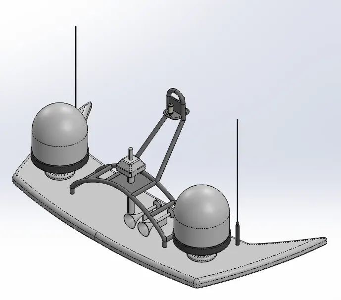
Radar Mast:
Front view:
Side view:
Isometric view:
Yacht Assembly:
Front View:
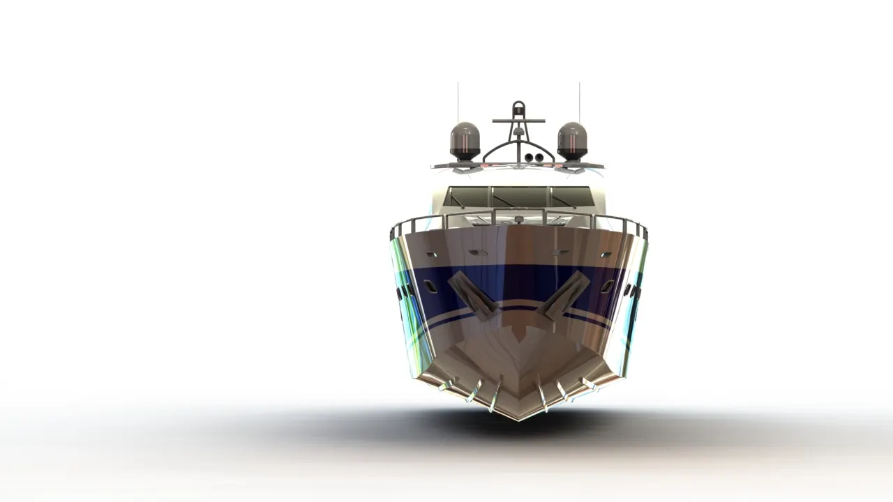
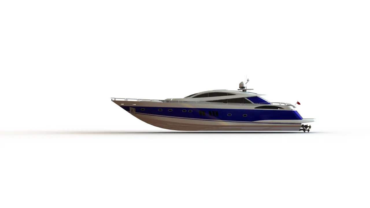
Side View:
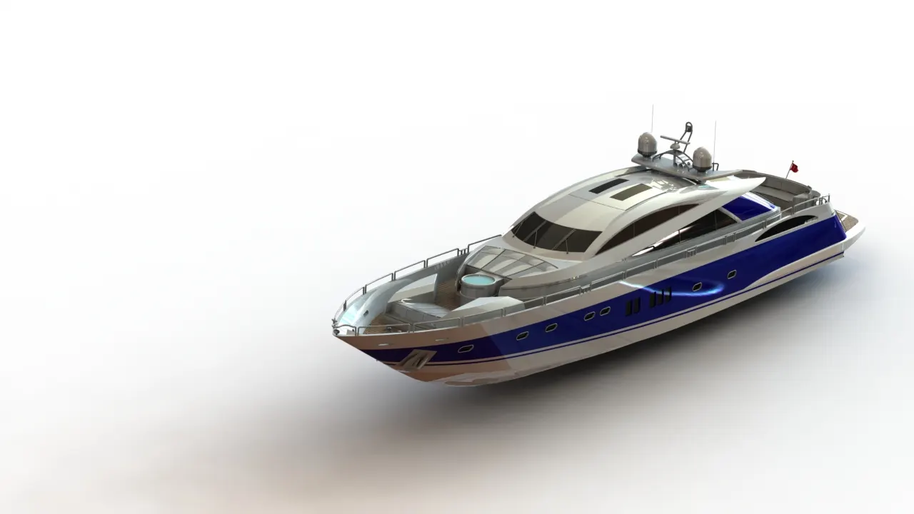
Isometric view:
Designing of Sunseeker Predator Yacht Assembly and Part Modelling
Objective:
The Objective of this project is to showcase the Yacht model and provide proper guidance for Designing and rendering of a Yacht Assembly. In this project you will see the Surface modelling being used for designing main components of Sunseeker Yatch. And also given a realistic look of Yacht by Photoview 360 in Solidworks.
Introduction:
Before going into the Designing methodology i would like to give a brief Introduction about Sunseeker Yacht and its history. "Sunseeker International" is a british luxury performance motor Yacht brand. Originally named Poole Power Boats, the company was founded by brothers Robert and John Braithwaite in 1969. It is the largest UK Based luxury Yacht maker measured by 2012 revenues.
A Yacht is a sail or power vessel used for pleasure, cruising or racing.To be termed a Yacht, as opposed to a boat, such a pleasure vessel is likely to be aleast 33 feet in length and have been judged to have good aesthetic qualities. Now that we have seen more about Yacht, lets plan action for designing the Yacht and its step by step metodology.
Design Methodology:
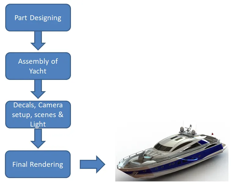
The method used here is Bottom-up designing procedure as follows,
1. Designing of piece parts and its appearence.
2. Assembly of Designed Yacht parts.
3. Applying Decals, Camera setup and scenes compositions.
4. Final Rendering.
1. Designing of Parts in Yacht:
Sunseeker Yacht contains more number of parts and I have made it easier and grouped them so that we will catagorize only few parts in this Assembly. This assembly comprises of 9 parts, they are
a. Radar
b. Propeller
c. Hull
d. Garage Door
e. Front seat
f. Middle seat
g. Rear seat
h. Super structure
i. Radar mast
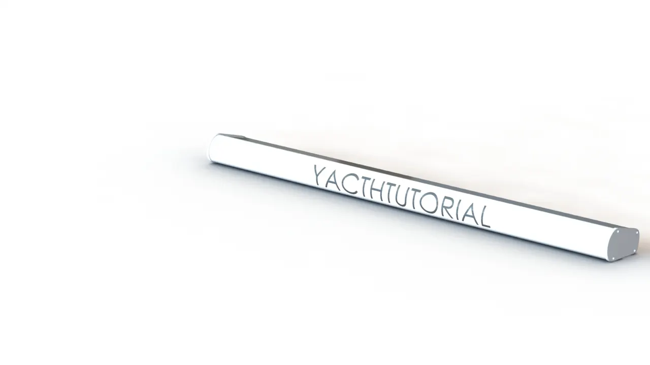
a. Radar:
A System for detecting the presence, direction, distance and speed of aircraft , ship and other objects by sending out pulses of radio waves which are reflected off the object back to the source.
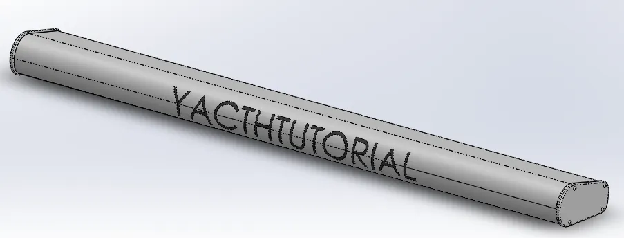
SolidWorks Image
Rendered Image
Feature tool: Extruded Boss, Cut, Sketch Driven pattern, Mirror, fillet and split line.
Sketch tool: Sketch Geometry like Line, circle, point, Text and Convert entities.
Procedure:
1. Select Right plane and sketch a trapezium using lines and extrude.
2. Sketch on face of previous extrude by converting sketch 1 entities and extrude.
3. Sketch on face of sketch 1 extrude by drawing a circle at a distance of 60mm from lower edge converted entity and
extrude.
4. Draw a cirlce on previous extrude face and do cut extrude.
5. Use sketch point to locate the previous extrude at required place and do sketch pattern.
6. Now mirror across the Right plane.
7. Draw a circle at lower edge of radar face and cut extrude.
8. Sketch on Outer face of Radar using line, insert text as of choice and split across line.
9. Finally give appearence the part.
b. Propeller:
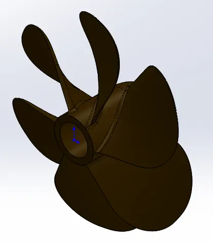
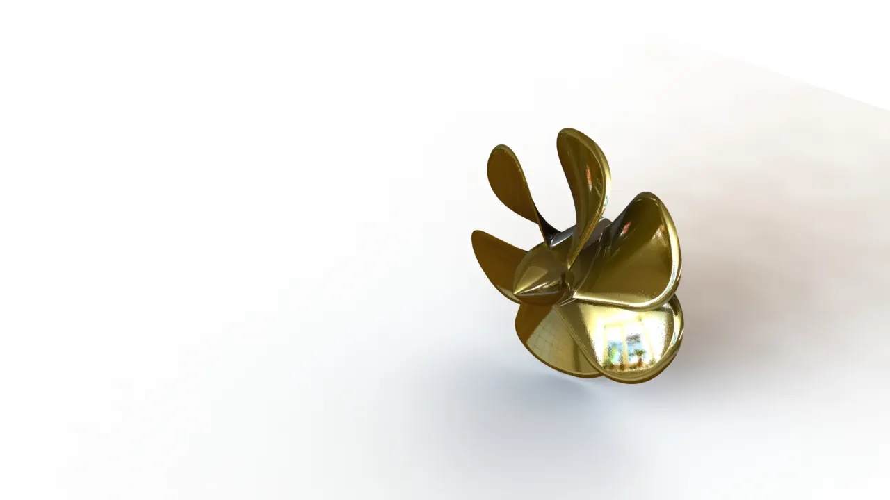
A Mechanical device for propelling a boat or aircraft consisting of a revolving shaft with two or more angled blades attached to it.
Solidworks Image
Rendered Image
Feature tools: Revolved Boss, Extruded cut, fillet and circular pattern.
Sketch tools: Sketch geometry like Line, spline, 3 point corner rectangle and circle.
Surface tools: Lofted surface.
Procedure:
1. Select the Right plane and draw a horizontal and vertical lines and a spline connecting left end points of horizontal lines
and revolve it.
2. Create a new plane, top plane as reference at an offset of 360mm.
3. Select the Top plane and draw a 3 point rectangle at an angle of 74 degree from bottom edge of revolve.
4. Create a new plane and draw a 3 point rectangle at an angle of 14 degree from similar edge.
5. Using above two sketchs create aloft and apply a fillet.
6. Draw a circle on the bottom face of revolve and cut extrude, apply fillet.
7. Give circular pattern of above feature with 6 instances equally distributed to 360 degree.
8. Give appearence to the part and save it.
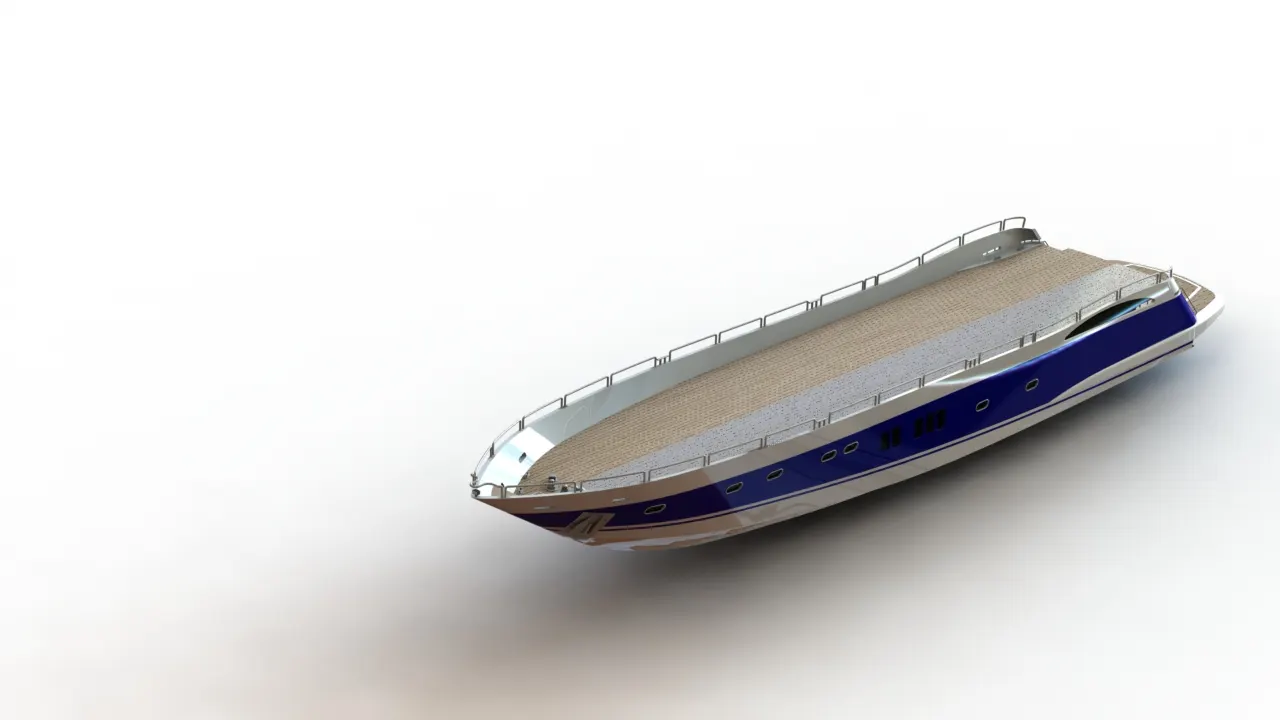
c. Hull:
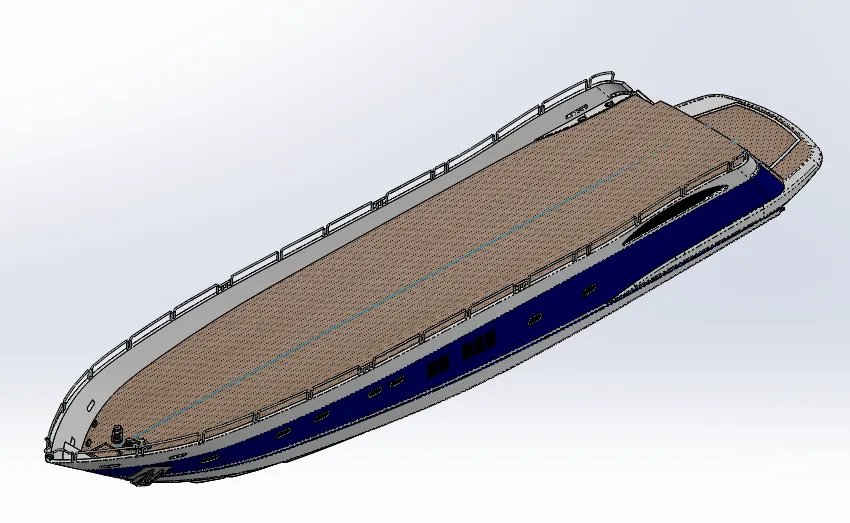
A Hull is the watertight body of a ship or boat. The hull may open at the top or may be fully or partially covered with
Deck. A top positioned deck may be deckhouse and other superstructures, such as funnels, derrick or Mast. The line where
the hull meets the water surface is called waterline.
Solidworks Image
Rendered Image
Feature tools: Revolved Boss, Extruded Boss & Cut, Projected curve, Split line, shell, copy and delete faces, Mirror, Helix,
Swept Boss, Chamfer, Fillet, and linear pattern.
Sketch tools: Sketch geometry like line, spline, fillet, slots, circle, trim, Convert extend and offset entities.
Surface tools: Lofted surface, Extended surface, filled surface, trim and knit.
Procedure:
1. Blue print setup - Insert all views like top view, front view, etc., by giving proper X,Y and Z direction dimensions.
2. Create 2 new planes Back plane and Top plane using Front and Bottom planes as reference.
3. Select the Bottom plane and draw a horizontal line and a spline with a midplane and define it fully with relations and
dimensions.
4. Select Midplane and draw a inclined line in Z direction, vertical centerline and a spline with 2 midpoints, drag the arrows
to make sure it matches the blue print.
5. Create a projected curve using the above two sketches.
6. Similarly create one more projected curve by drawing sketch on mid plane and bottom plane using lines and splines.
7. Select the back plane and draw a spline , use pierce relation to connect with projected curve.
8. Select the Mid plane and draw one more spline and use pierce relation again.
9. Now create a lofted surface using above two sketches.
10. Similarly create one more lofted surface by drawing sketches on midplane and back plane using spline.
11. Inorder to trim extra surface draw a vertical line in midplane and trim extra portion.
12. Select the midplane and draw a spline parallel to surface loft and do surface loft.
13. Select the midplane and draw a horizontal line and vertical and do surface extrude.
14. Trim extra surface and knit them together.
15. Make sure all edges of surfaces turns to black color which indicates the proper knitting.
16. Inorder fill the gap use the filled surface by drawing sketch on the midplane.
17. Now knit surfaces and create Shell.
18. Select the midplane and offset created surface entities inwards and draw a line to close the surface. Trim extra entities
using trim entities and extrude it.
19. Select Bottom plane and draw a sketch using 2 spline and do Cut extrude.
20. Apply fillets and chamfers to respectives edges.
21. For Side Windows - Draw four lines as a rectangle on plane 1 and apply fillets to corner, do linear pattern. Remove
extra created window and create a Cut Extrude.
22. For Port holes - Draw a straight slot on plane 1, copy the slot to another port hole using copy feature as per blue print
and do cut extrude. Create a 2D Sketch in new plane by drawing a circle and for profile create a 3D Sketches by
Converting port hole entities. Now create a solid sweep. Repeat similar steps for creating remaining port holes.
23. For Lower Deck - Create a Sketch on top plane as per Blue print using splines, line and do cut extrude.
24. For Staircase - Create a sketch on top plane by drawing a rectangle and do cut extrude. Select the extruded right
face and draw few connecting horizontal and vertical lines in form of stairs and extrude it upto next surface.
25. For Lower portion of Hull - Create a plane at an offset of 3000mm from bottom plane. Draw 3 spline and drag thier
arrows to match as per blueprint. Offset the spline and make it closed by lines and extrude it.
26. Draw a helix and create a plane using helix as reference, draw a circle at the end point of helix. Using Helix as path and
Circle as profile do sweep.
27. Draw a sketch on top face of the Hull using two circles and connect them with line and trim the inner half of circle to
extrude the lower surface of anchor house.
28. Create some extra port holes at front end and rear end woith help of few sketches, extrude them and do linear pattern.
29. Create a new Plane offset from the left face of stair sonnected portion, draw a sketch by 3 point center rectangle and
apply fillet to two top corners. Similarly do this in the another plane and sweep profile and path.
30. For Side Railing - Draw a sketch on mid plane by offseting inner edge of hull inwards, and outwards respectively.
Draw few vertical lines as per blueprint and trim the unwanted surface. Apply fillets and draw similar sketch on another
plane and do projected curve using two sketches. Draw a circle on the new plane at end of the curve and sweep it.
31. Draw a sketch on back plane using few lines and extrude it, to develop caliper surface. Select the surface of caliper,
draw a sketch as per blueprint and revolve it.
32. Create a sketch on back face of hull by drawing lines as per blue print and revolve it. Pattern it accordingly with help of
pattern direction sketch.
33. Draw a 3D sketch using a line to connect both propeller shaft holes and extrude it.
34. Draw a sketch on midplane at front portion of hull using lines and splines as per blueprint and extrude it and mirror it
across the respective face.
35. For Garage Door - Draw a sketch on midplane using rectangle and extrude cut. sketch on the extruded left surface
and convert the previous entities, cut extrude. Now use split and remove appropriate portion as Garage Door Body.
36. Create a pin by drawing a circle on previous extruded face and extrude it.
37. Create a sketch on mid plane by drawing splines and offset in upward and downward directions. Use split line and select
all faces to split.
38. Now give apperence to hull and mirror the whole half body and check all the appearence are correct.
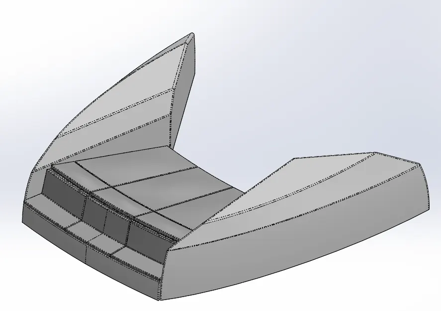
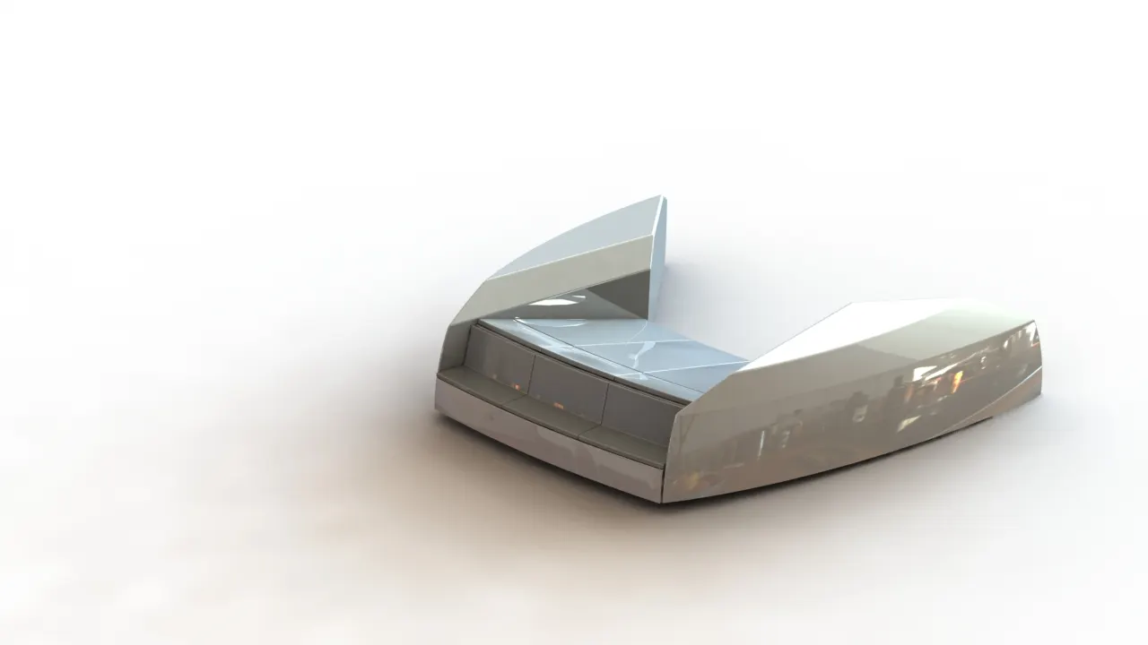
d. Front Seat:
Front Seat is located at the front end of the Hull which usually used for seating and enjoying the scenery.
Solidworks Image
Rendered Image
Feature tools: Revolved boss, extruded cut, fillet, mirror and Dome.
Sketch tools: Sketch geometry like line, spline and convert entities.
Surface tools: Lofted surface, swept surface, extruded surface, filled surface, trim and Knit.
Procedure:
1. Blue print setup - Insert all views like top view, front view, etc., by giving proper X,Y and Z direction dimensions.
2. Create two new plane back plane and top plane.
3. Insert hull part by select surface bodies.
4. Create sweep surface by creating a sketch on deck face and another sketch on new plane by drawing line.
5. Draw two lines and connect with the previous sweep surface and extrude it.
6. Trim the extra portion and filled gap with filled surface.
7. Draw few sketches according to few extra surfaces.
8. Create surface loft using above two sketches.
9. Trim the extra surface and knit it together.
10. Draw lines accordingly to create seat and revolve to 10 degree.
11. Apply fillet and mirror the bodies.
12. Finally apply Dome to seats and give appearence and save it.
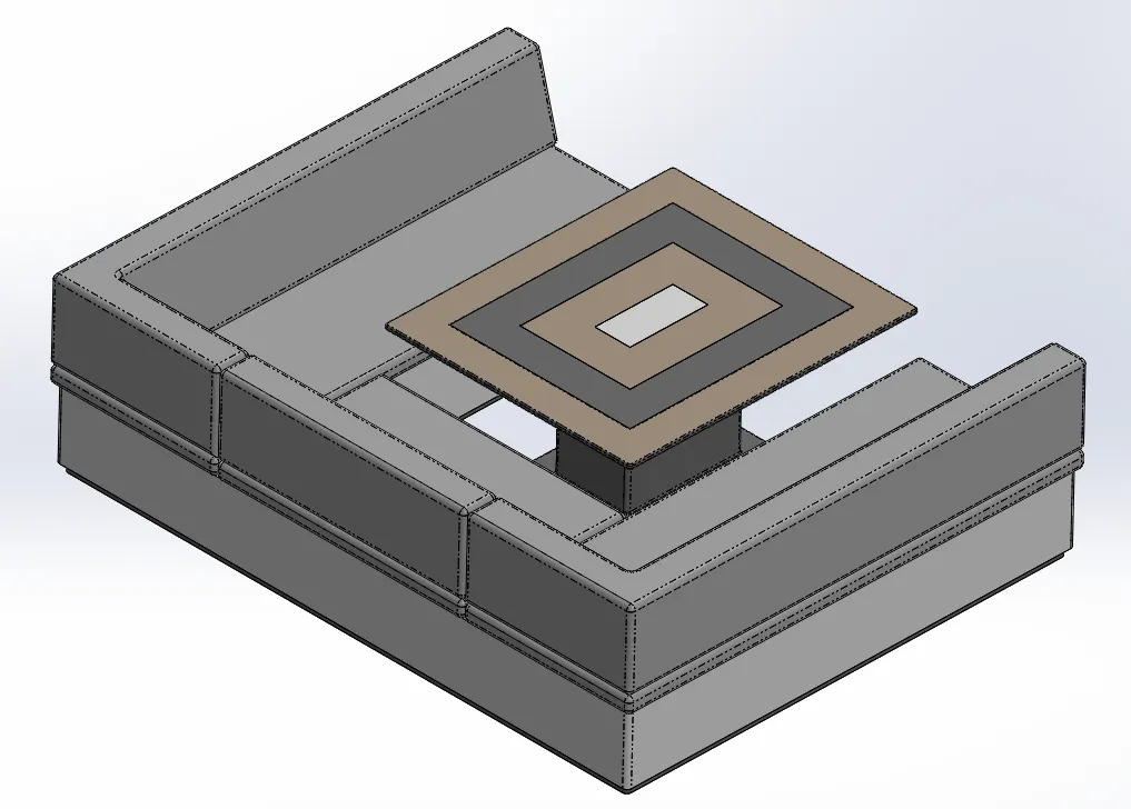
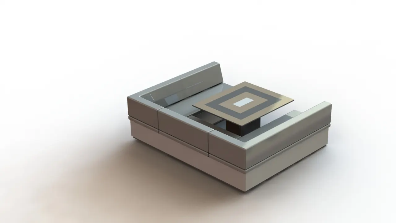
e. Middle Seat:
Middle seat is located just after the rear end of the super structure which is also used for seating and chilling out.
Solidworks Image
Rendered Image
Feature tools: Extruded Boss & Cut, Fillet and Mirror.
Sketch tools: Sketch Geometry like Line, convert entities and Offset Entities.
Procedure:
1. Blue print setup - Insert all views like top view, front view, etc., by giving proper X,Y and Z direction dimensions.
2. Create two new plane back plane and top plane.
3. Insert the Hull part by selecting the Surface bodies.
4. Draw a L shaped Lines on face of Deck and extrude for lower portion of seat.
5. Create a sketch on above extruded face and offset the surface and extrude it.
6. Create a plane on above extruded surface at offset distance of 5mm. Sketch on it by drawing line as per blueprint and
extrude it.
7. Mirror the bodies across the mid plane by selecting knit surface and merging solids.
8. Mirror seats across the midplane without the knit and merge options.
9. Create a table on the deck surface by using lines and offset entities.
10. Create a cut extrude at a top surface of table and apply fillets.
11. Finally give appearence to tables and seats and save it.
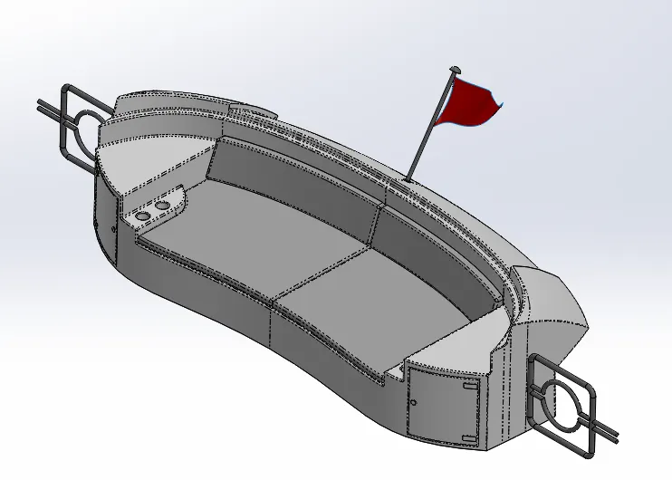
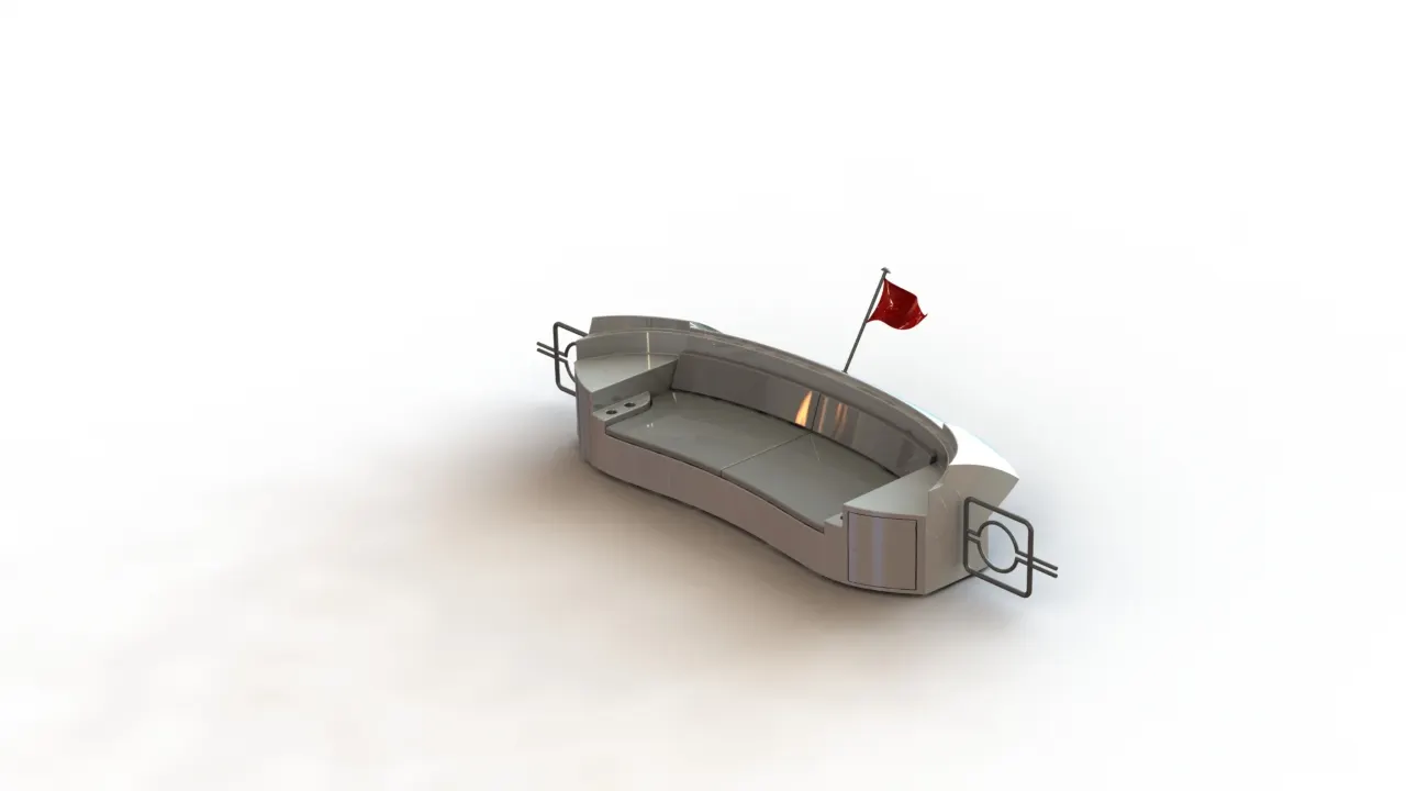
f. Rear Seat:
Rear Seat is situated at rear end of the Hull which is also used for seating and enjoying the view.
Solidworks Image
Rendered Image
Feature tools: Extruded Boss & Cut, Revolved Boss, Fillet, Chamfer and mirror.
Sketch tools: Sketch geometry like line, spline, convert and offset entities and trim.
Surface tools: Lofted Surface, Swept surface, Offset Surface, Ruled Surface, trim and knit.
Procedure:
1. Blue print setup - Insert all views like top view, front view, etc., by giving proper X,Y and Z direction dimensions.
2. Create two new plane back plane and top plane.
3. Insert the Hull part by selecting the Surface bodies.
4. Select the Mid plane and draw 2 splines as per blueprint and fully define it.
5. Create a plane using Deck face and vertex of spline as reference.
6. Create one more sketch on new plane by drawing a spline.
7. Now using above two sketches do surface sweep.
8. Create an offset surface by selecting previous sketches by selecting respective faces.
9. Trim the extra surface by drawing the sketches accordingly.
10. Use ruled surface to extend the surface and knit everything.
11. Draw a sketch on plane 1 using splines which is used to trim surfaces.
12. Create few planes and draw sketches by converting entities and splines and do surface sweep.
13. Extend the surface and trim the unwanted surface using surface trim and knit them.
14. Create few 3D Sketches and do surface loft.
15. Create sketch on Deck face by converting respective entities and splines with midpoint and extrude it.
16. Create Sktech on previous extruded face by selecting face and convert entities. Draw few lines as per blueprint and
extrude it.
17. Create a cut extrude by drawing a line on front plane.
18. Offset the appropriate faces for creation seats. Trim the surfaces by keeping the selection to split the surface.
19. Create a Boss extrude by drawing sketch on the offset surface using convert entities and lines. Apply chamfer and
fillets accordingly.
20. Create few planes as per the requirement and draw sketches accordingly using circle and line. Using these sketches
sweep and mirror it.
21. Create a sketch on plane 4 by drawing and extruding lines.
22. Mirror the bodies across the Midplane with Merge and knit options ON.
23. Mirror the Seats and gates across the mid plane without merge and knit.
24. Create a sketch on midplane by drawing lines and an angle and revolve it.
25. Create four 3D Sketch by drawing spline with midplane in eack sketch and loft surface.
26. Finally give appearences to Seats, Flag and other body part and save it.
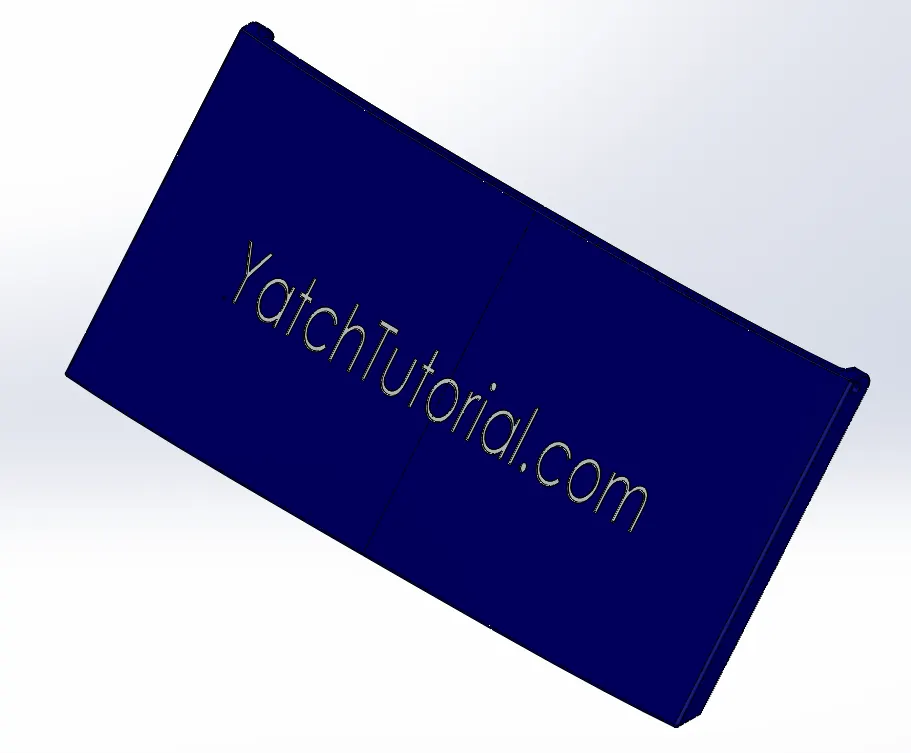
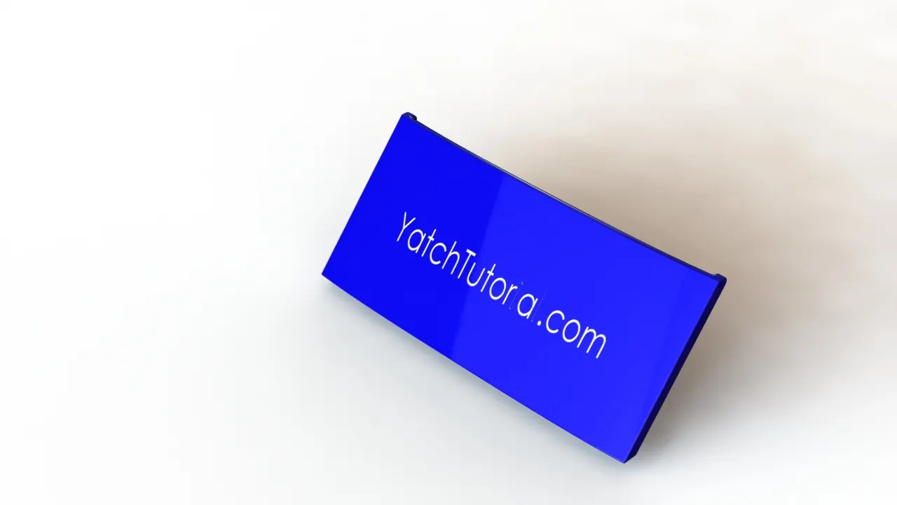
g. Garage Door:
Garage Door is used to close the parking space in which vehicles is parked in Yacht.
Solidworks Image
Rendered Image
Feature tools: Extruded cut, Fillet, Text, Shell and mirror.
Sketch tools: Sketch geometry like line, circle.
Procedure:
1. Open garage door part which was saved while designing Hull Part.
2. Create a Sketch on right face of stock by drawing lines and do extrude cut.
3. Apply shell by selecting face of the stock.
4. Draw a circle at the top by selecting side face of stock and do extrude cut to create a hole.
5. Aplly fillets and mirror across the right plane.
6. Create a plane using front plane as reference and offset it.
7. Draw a sketch on that plane with horizontal line and insert Text in text box, do cut extrude.
8. Finally give appearence to the Door and text and save it.
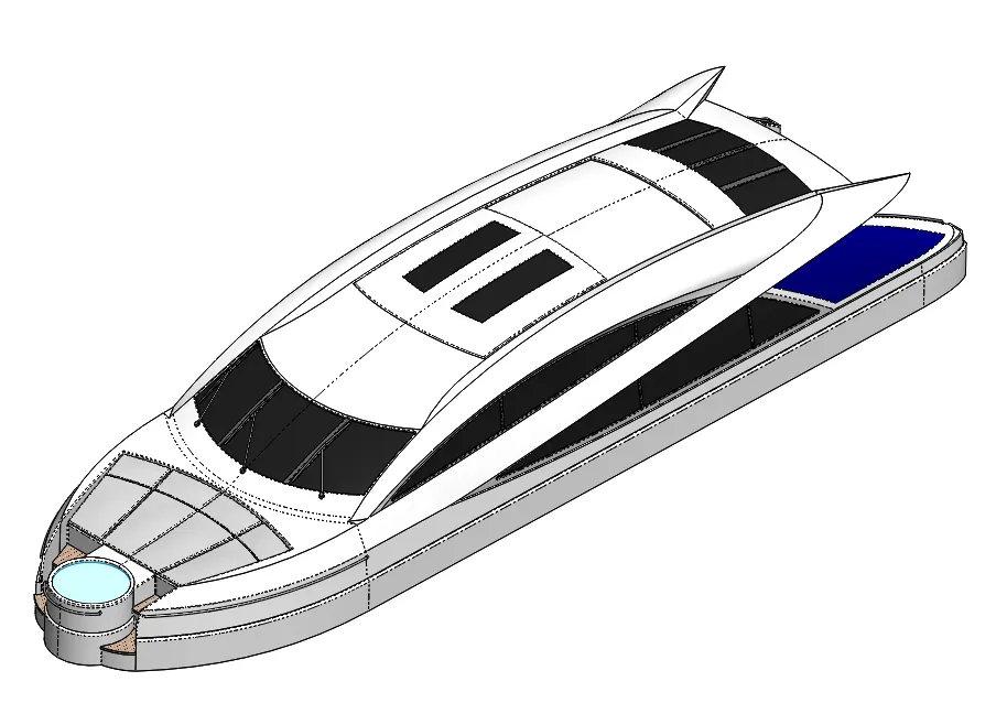
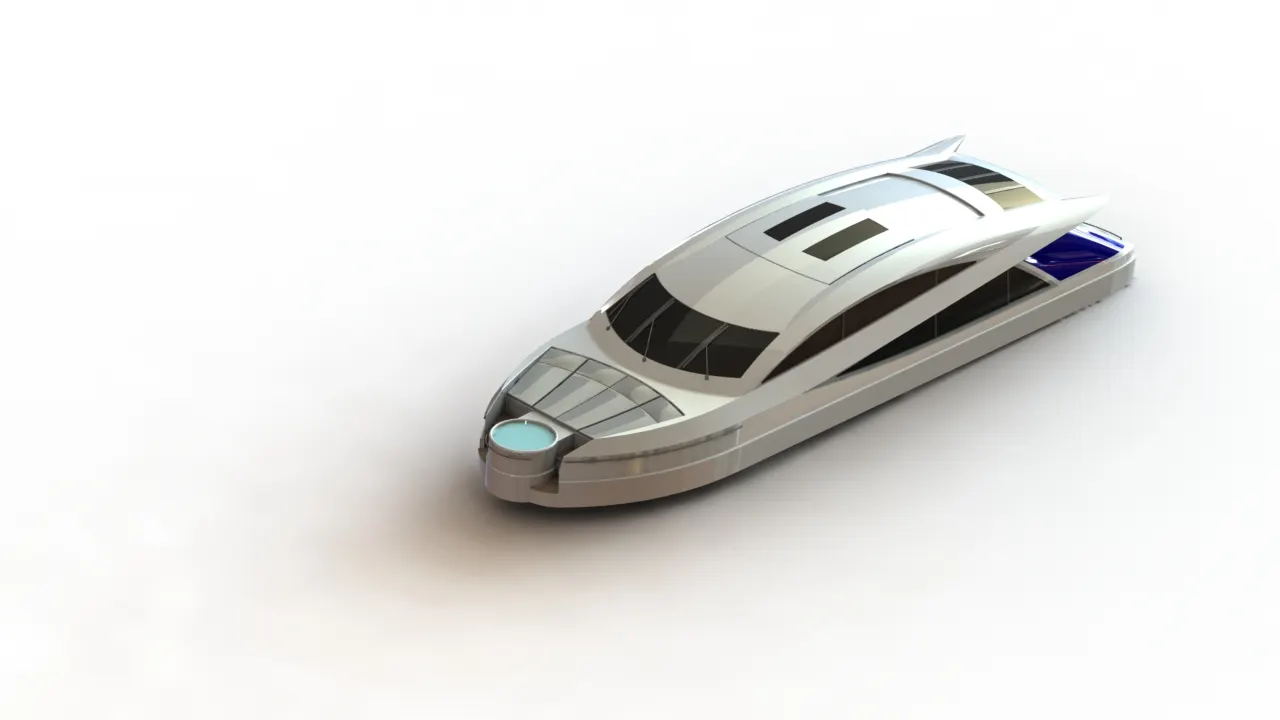
h. Super Structure:
A Super structure is an upward extension of an existing structure above a Baseline. It is located on the top of the
Yacht and contains the operater cabin and other important performance monitoring place inside it.
Solidworks Image
Rendered Image
Feature tools: Extruded Boss & Cut, Projected curve, Split line, Delete face, mirror, swept boss, chamfer, Fillets.
Sketch tools: Sketch geometry like Line, spline, rectangle, fillet, circle, convert entities and offset entities.
Surface tools: Lofted Surface, Extended surface, Filled Surface, extrude surface, trim and knit.
Procedure:
1. Blue print setup - Insert all views like top view, front view, etc., by giving proper X,Y and Z direction dimensions.
2. Create two new plane back plane and top plane.
3. Insert the Hull part by selecting the Surface bodies.
4. Create a Sketch on Deck surface by drawing a two spline and a line as per blueprint and extrude the surface.
5. Create the plane at end of the created surface extrude.
6. Create surface sweeps by drawing sketches on created plane using horizontal line and apply pierce relation with
extruded surface. A 3D Sketch by converting outer surface as entities.
7. Extend th outer edge of the surface using ruled surface at an angle and trim and knit all surfaces.
8. Create one more projected curve by drawing two sketches on respectives planes using splines and line and create
lofted surface.
9. Create one more surface sweep by drawing sketches on created plane using horizontal line and apply pierce relation
with extruded surface. A 3D Sketch by converting outer surface as entities.
10. Trim the unwanted surfaces on the plane.
11. Create swept surface by drawing a sketch on midplane using splines and 3D Sketch by converting respective edges.
12. Trim the extra surfaces on the plane.
13. Similarly for creation of surfaces on top, draw two sketches on respective planes to get projected curve as per
blueprint which is further used to create lofted surface.
14. For Side Windows - Select the outer surface of super structure use ruled surface for extension.
15. Trim the extra surface on the respective planes.
16. Select the deck face and create a sketch by drawing a line at rear portion and do surface extrude. Trim extra surface
Knit them.
17. Draw a sketch on mid plane by converting respective edges and do surface extrude. Trim extra surface Knit them.
Create one more sketch on midplane by drawing line and spline and do surface extrude.
18. Select the deck surface and sketch a circleand extrude cut. Draw 2 more circles to extrude. Apply fillets and cut
extrude it to show only half of it.
19. Draw horizontal and vertical lines accordingly and extrude them. trim the extra surface.
20. Inorder to make it solid sketch on the deck surface by drawing a horizontal line and do surface extrude. Trim extra
surface and knit it ot merge as solid.
21. Create a surface offset at front end and trim and thicken the respective surfaces. Create cut extrude and apply dome
and fillets to it.
22. Create sweeps by drawing sketches on respective planes using circle and splines.
23. Create a cut extrude by offseting rear face inwards. Draw a L Shape and extrude it for handle creation.
24. Create a sketch on top plane by offseting entities and do cut extrude.
25. Sketch on respective face by drawing two vertical lines and converting top and bottom edges of glass.
Trim unwanted entities and do extrude.
26. Create a sketch on top plane by drawing a line, spline and do cut extrude.
27. Create a sketch by offseting respective edges and trim unwanted entities and extrude it.
28. Similarly create windows and frames for side faces by drawing few sketches and doing etrude boss.
29. For rear portion draw sketch on the mid plane by offseting respective face and do split line.
30. Create a sketch on top face on super structure by drawing one circle and a half circle, extrude it.
31. Mirror the bodies across Midplane with merge and knit options.
32. Create a offset surface for radar mast by selecting on the top of super structure face.
33. Using Boss extrude and Cut extrude draw few sketches to create three wipers in the front window.
34. Give appearence to windows, Doors, Frames, Mattress, Wipers, Railings and super structure body and save it.
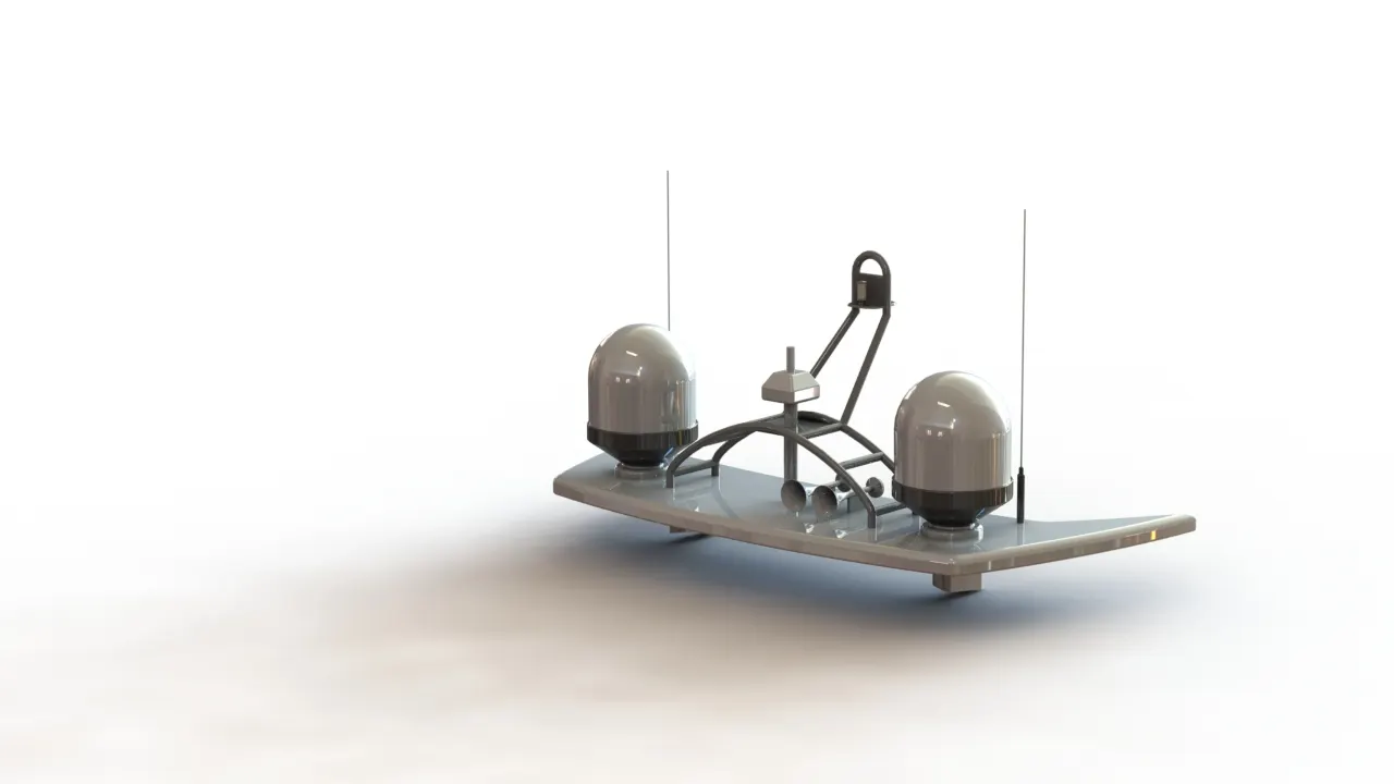
i. Radar Mast:
Radar is a detective system the uses radio waves to determine the range, angle and velocity of objects. A radar
system consists of transmitting antenna, a receiving antenna and a receiver and a processor to determine the properties
of the object.
Solidworks Image
Rendered Image
Feature tools: Extruded Boss, Revolved Boss, Projected curve, Mirror, Swept boss, chamfer, fillet.
Sketch tools: Sketch geometry like Line, spline, rectangle, 3 point arc, straight slot, circle.
Procedure:
1. Blue print setup - Insert all views like top view, front view, etc., by giving proper X,Y and Z direction dimensions.
2. Create two new plane back plane and top plane.
3. Insert the Hull part by selecting the Surface bodies.
4. Create a sketch on surface of radar mast by drawing a horizontal line at at distance of 160mm from the surface and
apply fillets to outer and inner edges.
5. Draw 4 spline and a line as per blue print and extrude it on created plane.
6. Draw a sketch on top face of previous extrude using a line and 3 point arc, revolve it. Draw a circle on extrude face,
extrude it and apply fillets.
7. Create sketch on extrude 1 face by drawing a circel and extrude it. Draw one more circle on extruded face and extrude
it. Do again on that surface by drawing a circle.
8. Create a sweep by drawing a spline and a circle in the 3D sketch.
9. Mirror the above sweep across plane 2 and connect them by 3 circles and sweeping extrude them.
10. Create a projected curve as per requirement by drawing sketch on respective plane.
11. create sweep by drawing a circle at edge of the projected curve.
12. Draw few line and splines as per blue print do revolve. Apply Dome to one end and shell other end.
13. Mirror evreything except horns across the midplane.
14. Draw a straight slot on the radar face and extrude upto horn to make it as a stand.
15. Create plane using above extruded right face and offset it. Mirror the horn across this plane.
16. Finally give appearence to radar mast, antenna, horn and indicators and save it.
2. Assembly of Yacht:
Procedure:
1. Create a new assembly and import Hull and fix it in this assembly.
2. Now insert all the parts one by one and give mate conditions as per the components location.
3. Make sure few rotatable parts like Propeller, Radar, Garage door should be left free for one degree of freedom.
4. Check the component appearences and save the assembly.
Rendered Images of assembly:
Front View:
Side view:
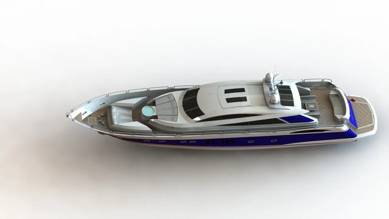
Top View:
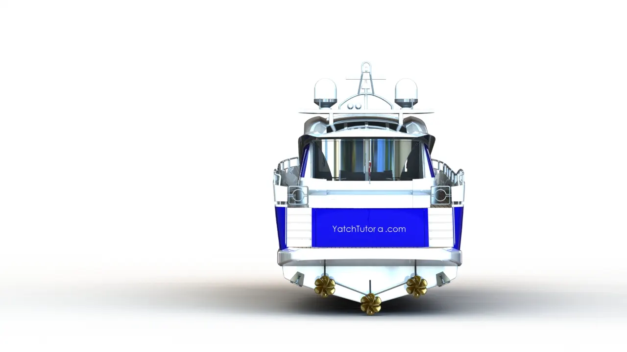
Back View:
Camera View:
3. Appyling Decals, Camer setups & Scenes composition:
In this section Decals ( Special Designed papers) are applied to
a. Hull- Main floor, Mood board, front end and Stair case.
b. Super structure - Staircase.
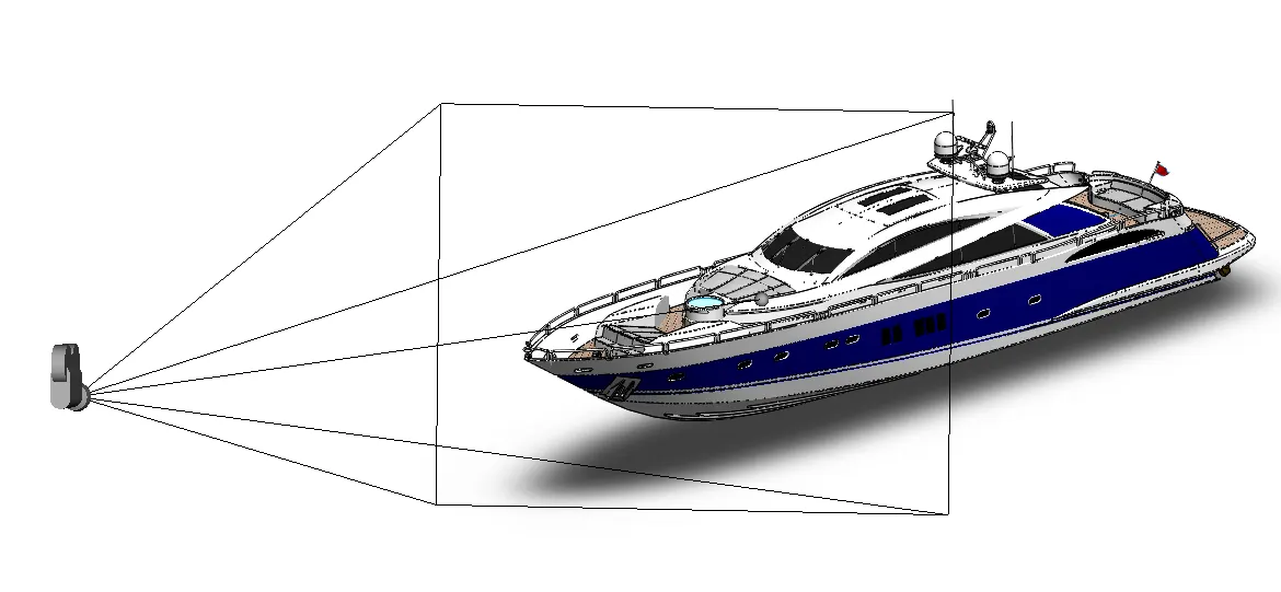
Setup a Camera and appropriate scenes to get realistic images whiling rendering.
4. Final rendering:
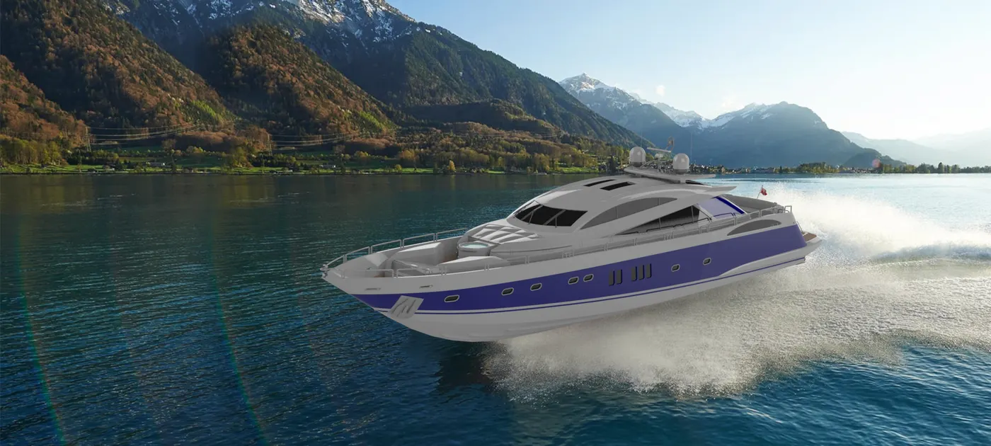
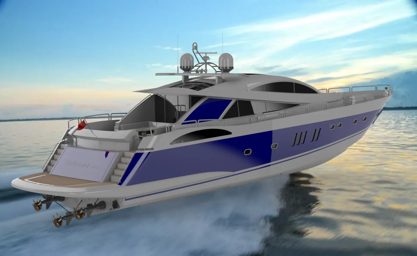
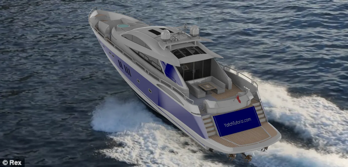
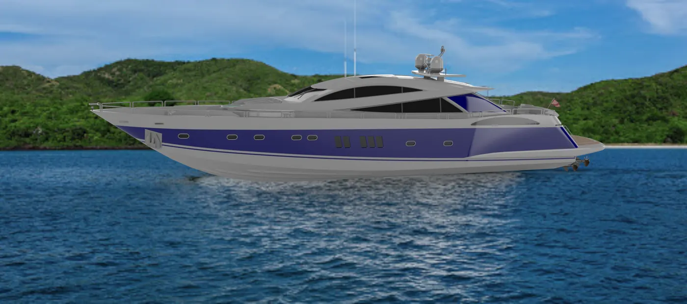
In this our Yacht assembly is rendered in photoview 360 and Solidworks Visualize as shown below.
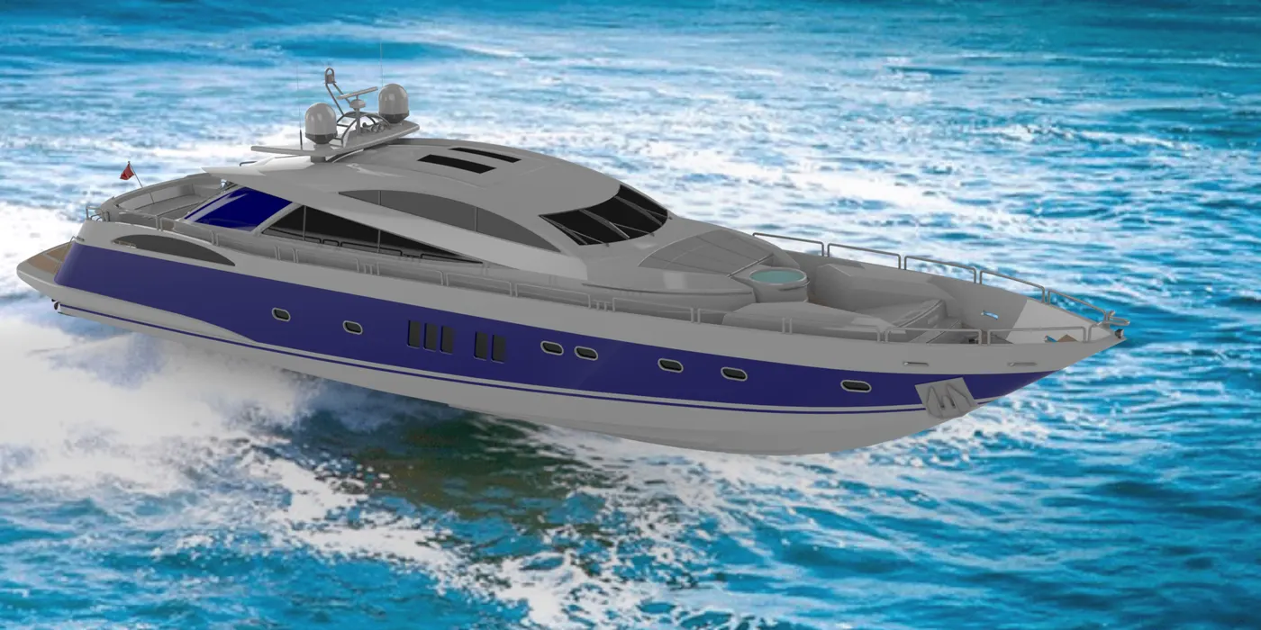
Conclusion:
These are the result of Proper design methodology for modelling and rendering of Yacht in Solidworks using Photoview 360 and
Visualize softwares. I hope this will help you in easy plan action for designing and also rendering.