Advanced Sheet Metal Design Using NX Cad Challenge_6_Bracket
Simple Bracket Design from 2D to 3D using NX Cad.
Objective:
This project is useful in understanding the drawing and annotations and implementing it in the 3D model to get the same result.
It will enhance your readability towards the engineering drawing much more than a tutorial.
Introduction:
It is a 'L' shaped bend bracket used for mounting or fitting the components. The design of this bracket is simple yet it is very important to learn
and accessing the drawing information and converting into 3D model with same annotations and shape. In this project, you will learn how to use
beads, bending and holes.
Design Methodology:
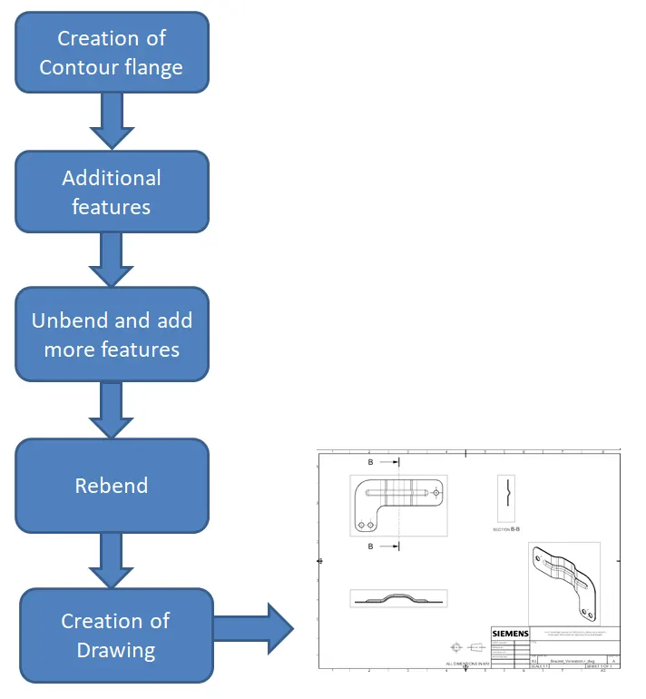
Description:
1. Create a sketch on plane XZ and create contour flange by selecting that sketch with 3mm thickness and 200mm wide.
2. Create another sketch on the top plane and use Normal cut option to bring the profile of part.
3. Break all the sharp edges and corners 25mm, 30mm, 60mm as shown in the drawing.
4. Now Unbend the sheet and select the top surface on the part and draw a line 250mm long.
5. Select the bead and click that sketch with 7mm depth and 7mm radius and 5mm as die radius.
6. Now rebend the sheet by selecting the bend ares.
7. To ensure that there is no changes made due to this bending, check the bead radius by selecting the Local Radius analysis option.
8. Now select the top surface and create 3 number of holes with 20mm diameter at each corners.
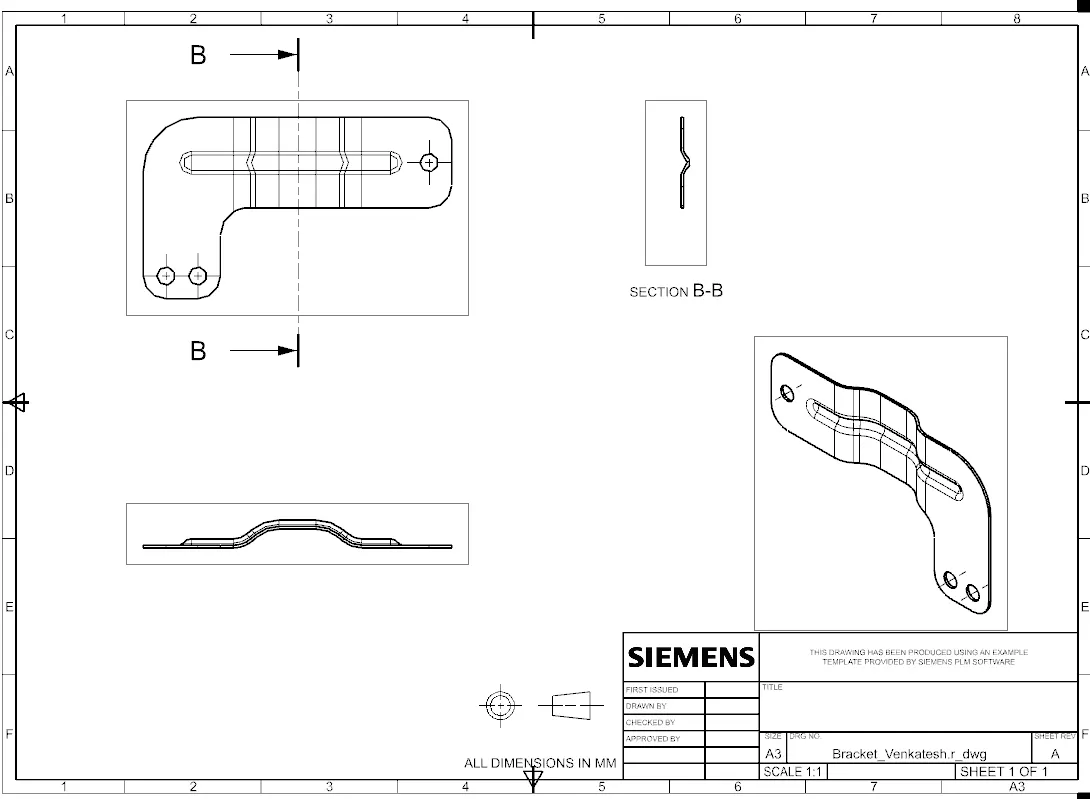
9. Create a new drawing and place the base view followed by the projection views and section views.
10. Now Save the Drawing and model in the name of Bracket.
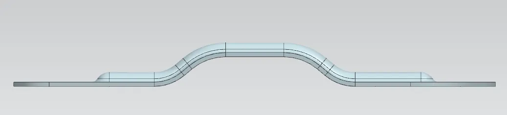
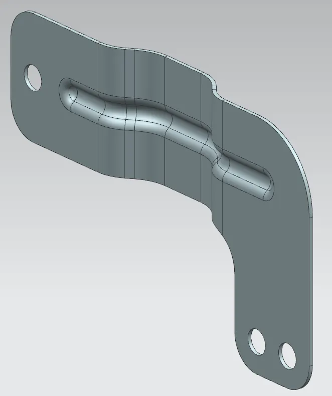
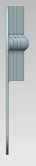
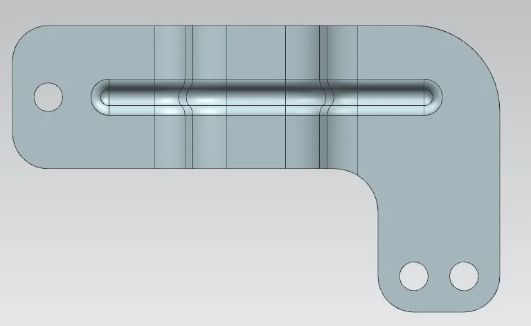
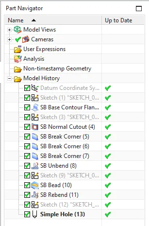
Here are some images of the Bracket model and drawing,

Conclusion:
Thus the simple bracket design from 2D to 3D is completed in the minimum and efficient way using NX Cad software.
I hope this is useful for you guys, Thank you.