Advanced Sheet Metal Design Using NX Cad Challenge_2_Box Assembly
Sheet metal Box Assembly using NX Cad
Objective:
In this project we going to design Box Assembly as single sheet metal part using NX Cad software.
Introduction:
This Box Assembly consists of a container, Hinges and Tight fit Lid. All the components are modelled as a single
sheet metal part with uniform thickness. In this project we will learn few new features like Hem, Mirror, etc., All the
Dimensions are in "mm".
Design Methodology:
As an assembly, the design methodology will be the 'Bottom-up' method but here we are going to design as a part so,
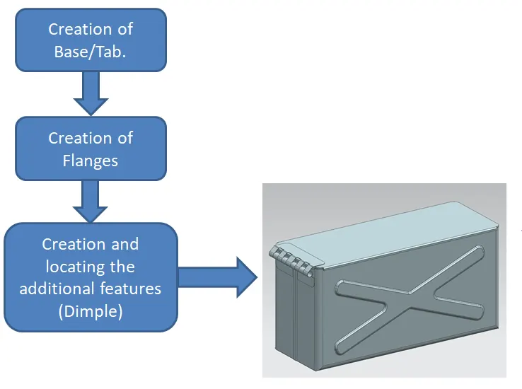
Description:
1. Go to Menu- Preference - Sheet metal and set all four values to 1 mm.
2. Select the XY Plane and draw a rectangular Tab of 200mm X 150mm with 1mm as thickness.
3. Create a flange with 200mm length perpendicular the tab, 10mm as bend radius.
4. Select the one side edges of these two flanges and create another flange towards them upto 70mm perpendicularly.
5. Maintain the Bend radius as 10mm.
6. Give Close and relief to these flanges.
7. At the front end of these flanges, create a flange with 0.02mm length and 0mm as bend radius, 90 degree.
8. Another flange - 6.5mm, 90 degree, 0.5mm bend radius. And repeat it for other flange also.
9. Select the Hem option and create on both edges with 0.5 bend radius, 5mm length.
10. Now mirror the body with respect to the YZ Plane to get a container as a result.
11. Create the Dimple sketch as shown in the image and use 2mm depth as material outside.
12. Now Mirror this Dimple on the other side of the box with ZX as Mirror plane.
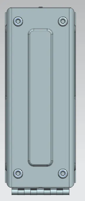
13. Create a rectangle dimple with 2mm material inside on the bottom of the Box.
14. Use Circular bead option for the bottom side of the box with 2mm depth and apply it in all four corners.
15. Create Close loop Hem in all 3 edges of Box upto 2mm length.
16. Create a plane 202mm away from XY plane and draw a sketch which fully enclosing the box edges.
17. Give tab as 2mm for that sketch and create flanges on the three edges of the Tab.
18. Now Create Sketch for modelling Hinge using Tab, Flange, Mirror options.
19. Similarly create opposite Hinges and Cut and bend them respective to the other hinges.
20. Now save the assembly and name it as 'Box Assembly'.
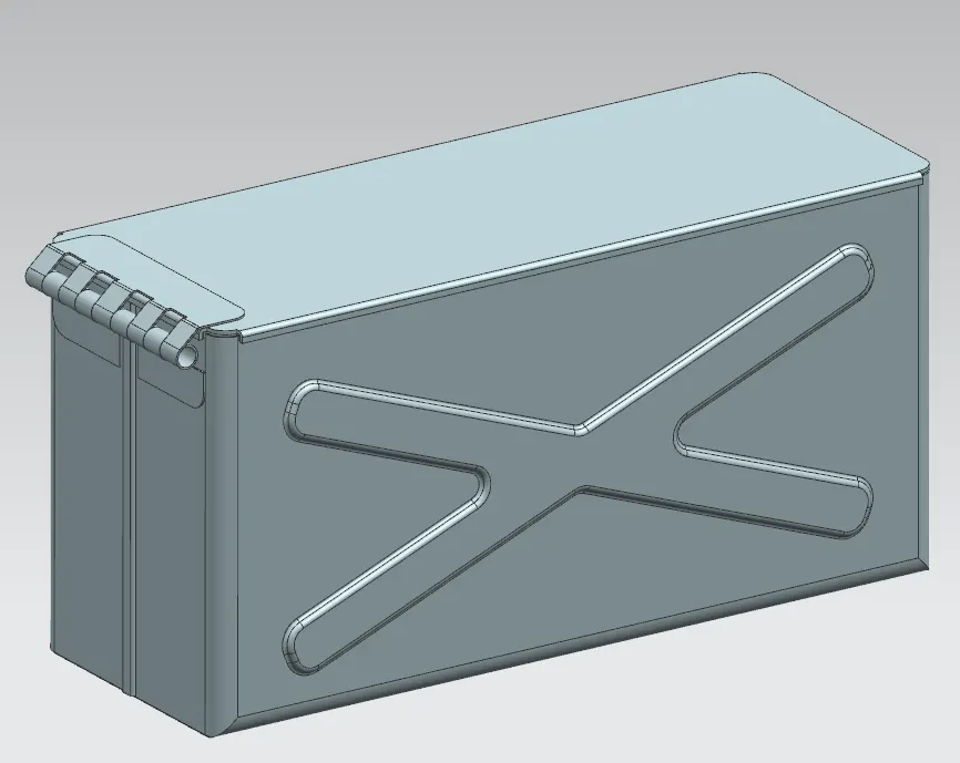
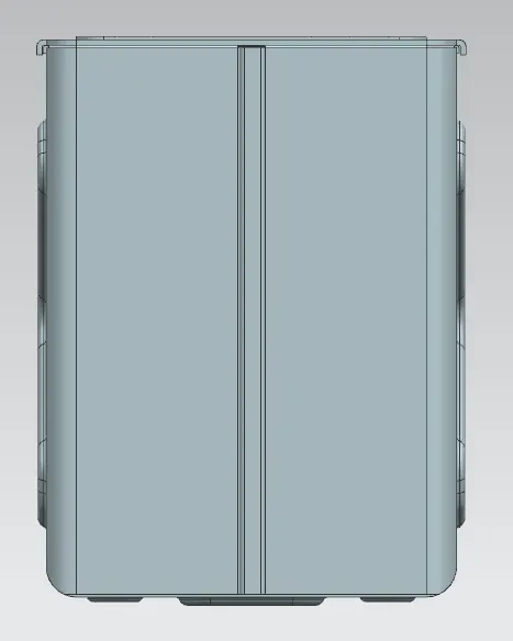
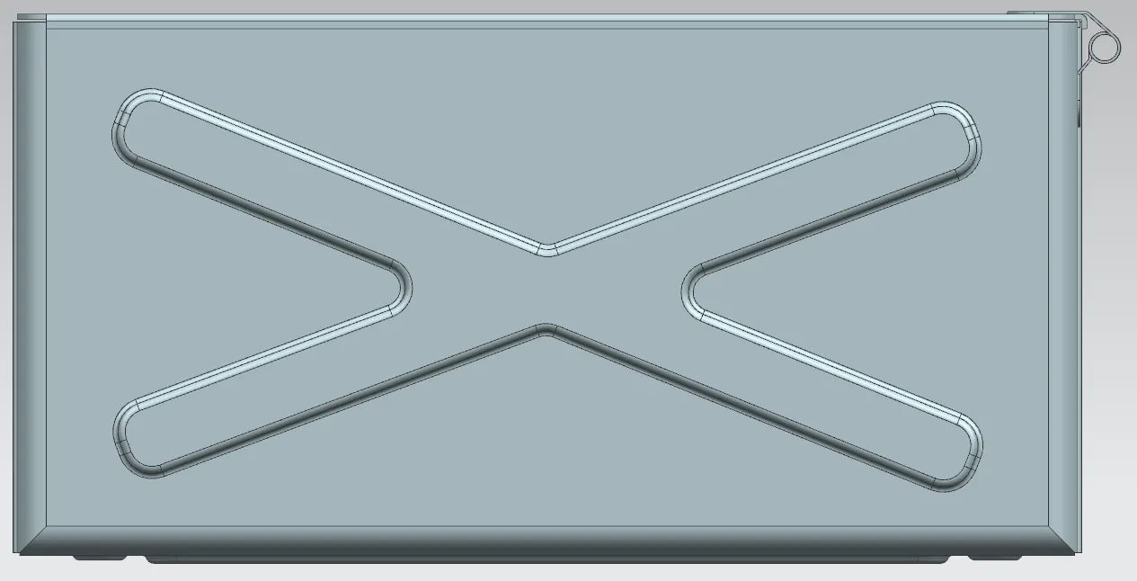
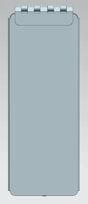
Here are some of the images of assembly,
Conclusion:
And Finally we have seen the clear process and details of creating a Box Assembly design using sheet metal in NX Cad
Software. I hope it will be useful for you guys.