Analysis & Design of RCC shear walls in the model using ETABS
Challenge-10
Analysis & Design of RCC shear walls in the model using ETABS
The etabs file for a G+6 building is provided. Run the analysis and design the RCC shear walls (show in the etabs model). The following challenge deals specifically with the shear wall of size 300x1500 at grid A-11 in the structural model.
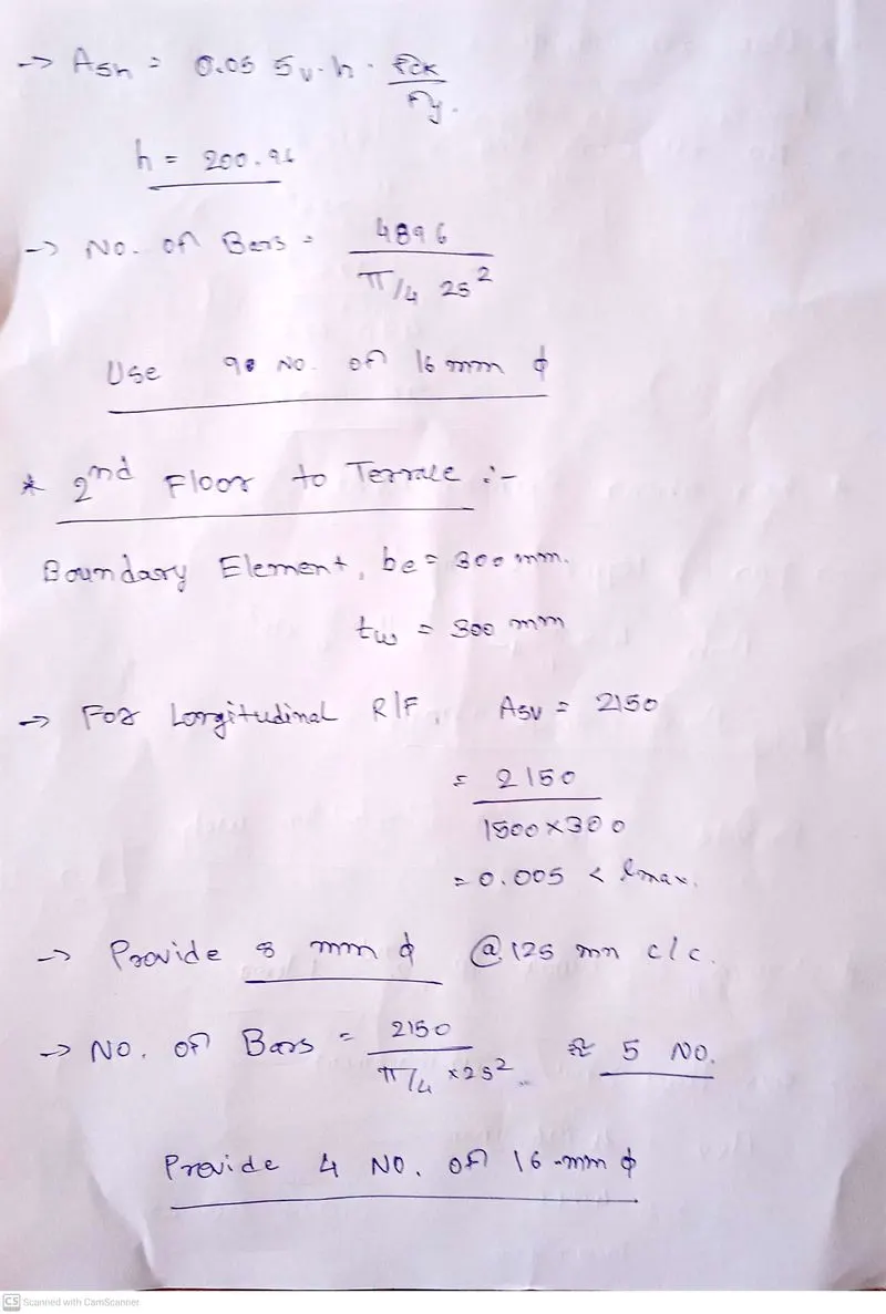
- Extract values of longitudinal steel ratio, boundary element length and shear reinforcing ratio from the design results.
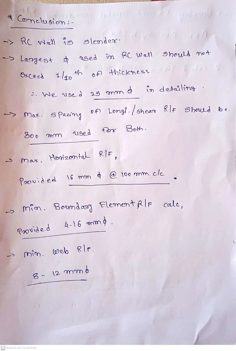
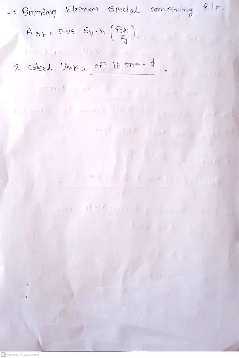
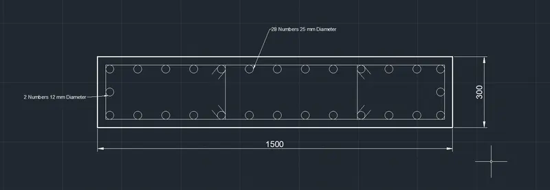
- Provide cross sectional steel arrangement of the shear wall from its base up to terrace, in compliance with provisions of IS 13920 – 2016. AutoCAD application can be used for this exercise. Alternatively, it can be drawn by hand as well.
- Provide elevation drawings of the reinforcement details of the shear wall from base up to terrace.
Introduction :-
- Shear wall, In building Construction, a rigid vertical diaphragm capable of transferring lateral forces from exterior walls, floors, and roofs to the ground foundation in a direction parallel to their planes. Examples are the reinforced-concrete wall or vertical truss.
- Reinforced concrete (RC) shear walls are widely used in medium- to high-rise buildings to provide the lateral strength, stiffness and energy dissipation capacity required to resist lateral loads arising from wind or earthquakes.
- But at the end of each wall, bars are closely spaced and anchored. So, the end zones of RC shear wall is called as boundary elements or barbells.
Aim:-
- To extract values of longitudinal steel ratio, boundary element length and shear reinforcing ratio from the design results and to provide cross sectional steel arrangement of the shear wall from its base up to terrace, in compliance with provisions of IS 13920 – 2016.
- To provide elevation drawings of the reinforcement details of the shear wall from base up to terrace.
Procedure :-
- First we have to open the challenge and download the challenge.
- After downloading the challenge open it in ETabs, as shown below.
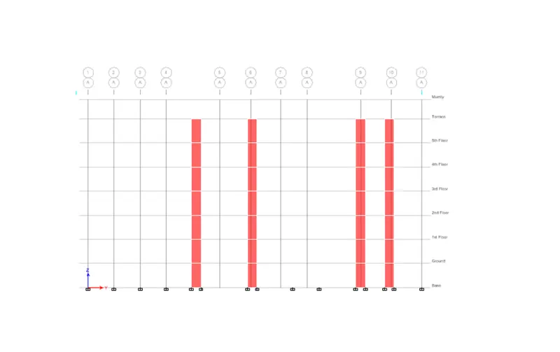
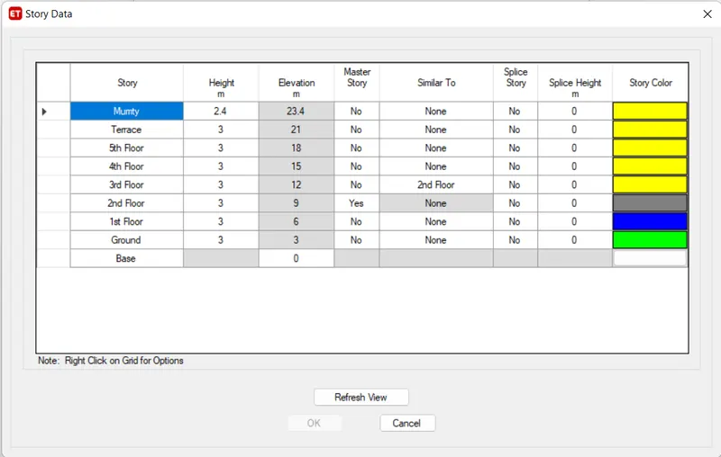
- Now change the elevation so that shear wall of size 300x1500 at grid A-11 in the structural model is visible in the structure.
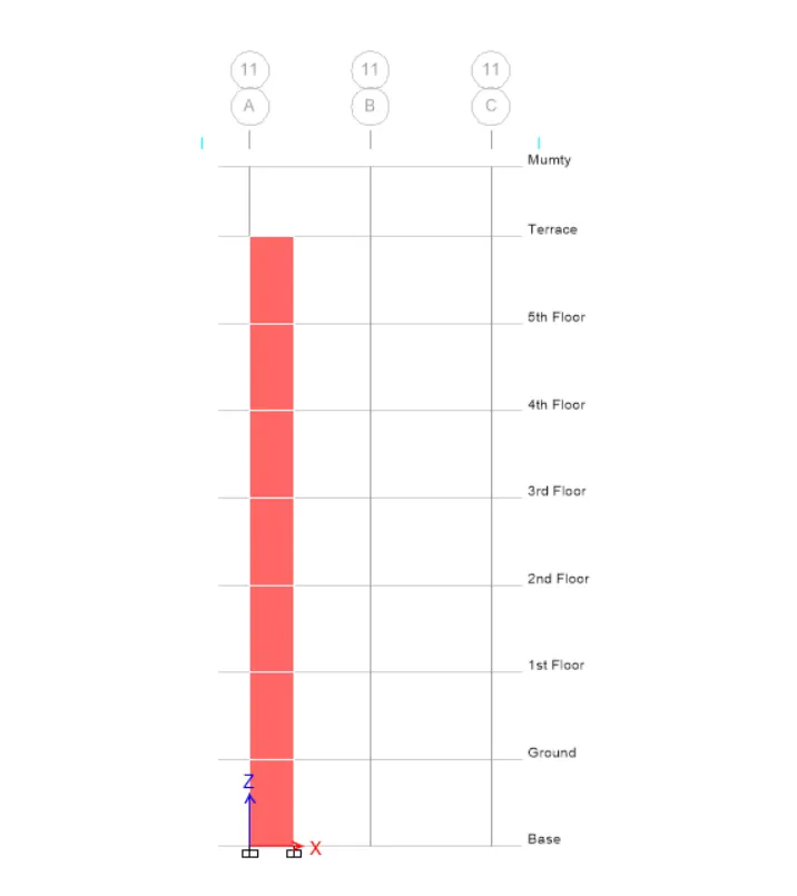
- Now check the poer is assigned or not.
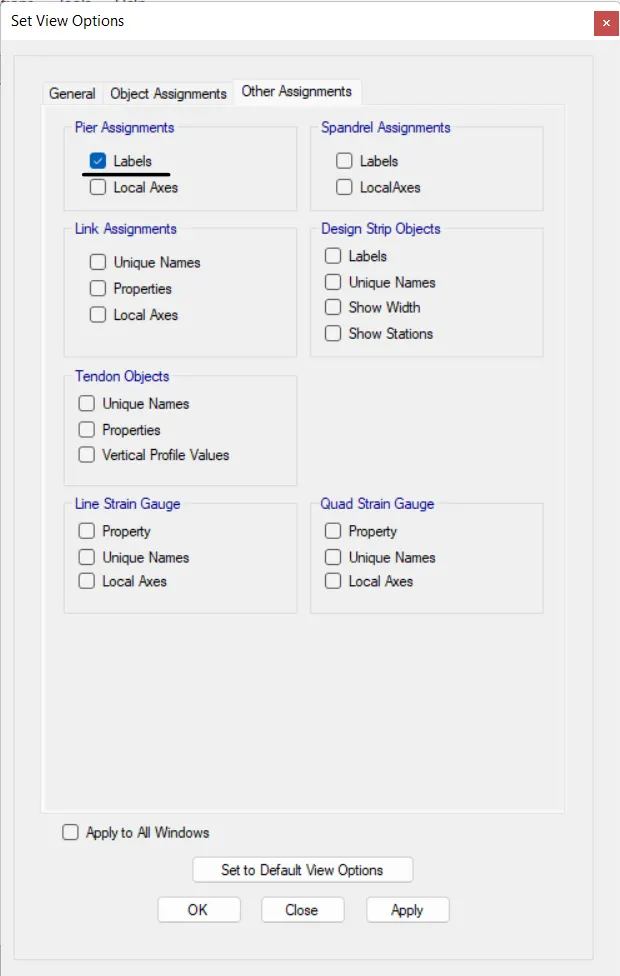
- Go to display option -> Other Assignment -> Pier Lable.
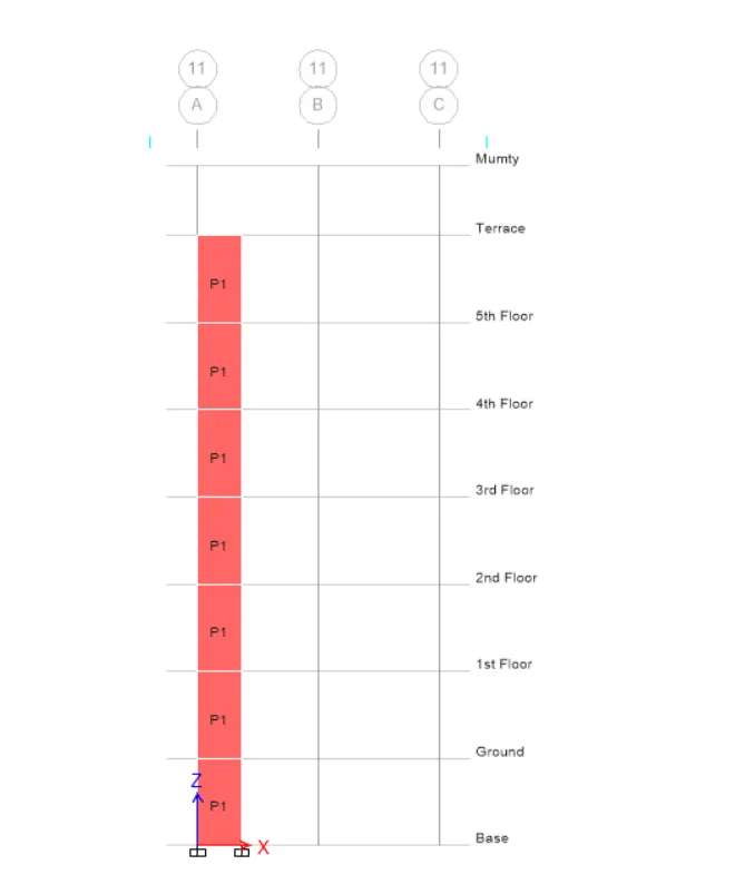
- Now Run the Analysis.
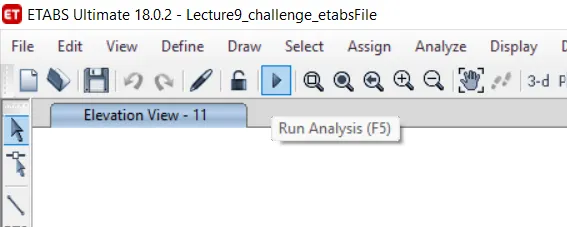
- Analysis is Done.
- Now Go to shear design option.
- Select Start Design/Check option.
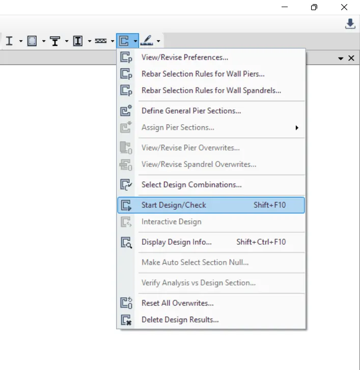
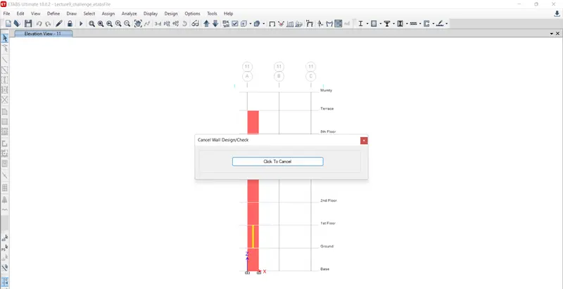
Extract values of longitudinal steel ratio, boundary element length and shear reinforcing ratio from the design results.
- Now go to Display Design Info.
- Select Pier Logitudinal Reinforcement option.
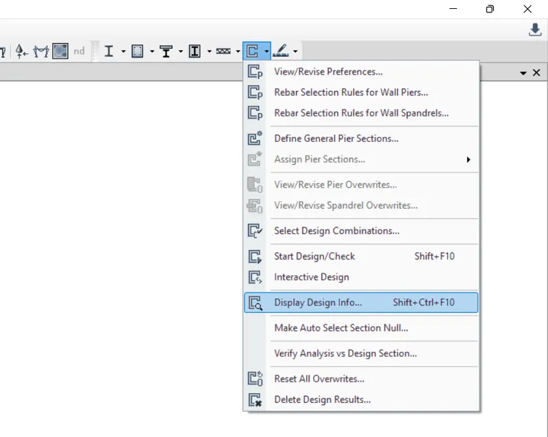
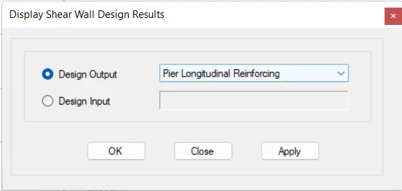
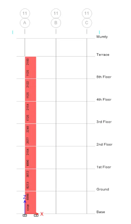
- Now go to Display Design Info.
- Select Pier Shear Reinforcement option.
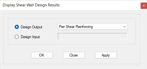
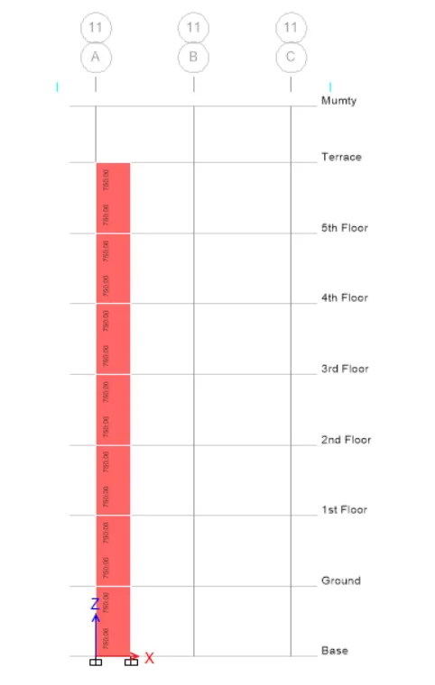
- Now go to Display Design Info.
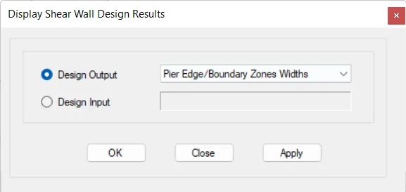
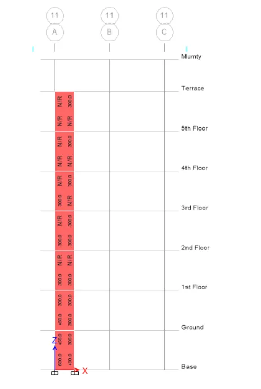
- Select Pier Edge/Boundary Zones Width option.
Provide elevation drawings of the reinforcement details of the shear wall from base up to terrace.
- Elevation drawings of the reinforcement details of the shear wall from base up to terrace is as per following.-+
Elevation-A :-
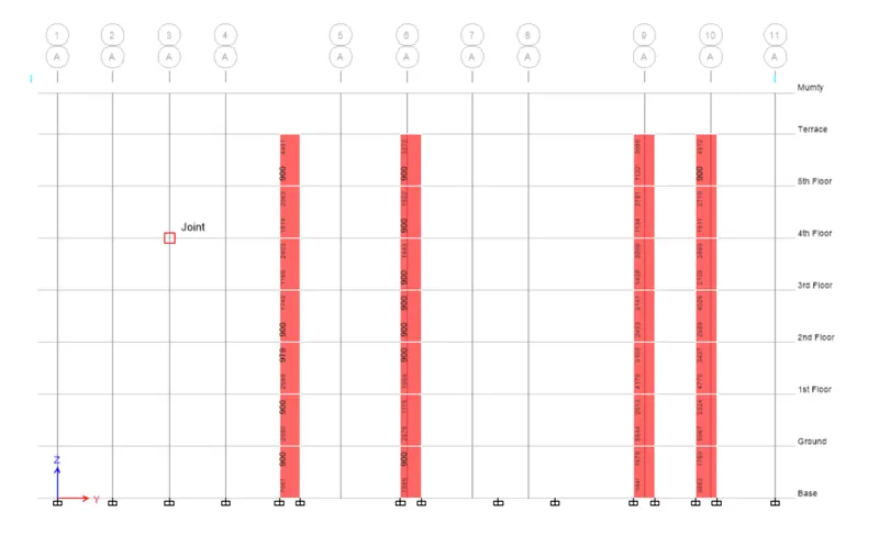
Elevation-C :-
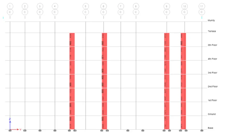
Provide cross sectional steel arrangement of the shear wall from its base up to terrace, in compliance with provisions of IS 13920 – 2016. AutoCAD application can be used for this exercise. Alternatively, it can be drawn by hand as well.
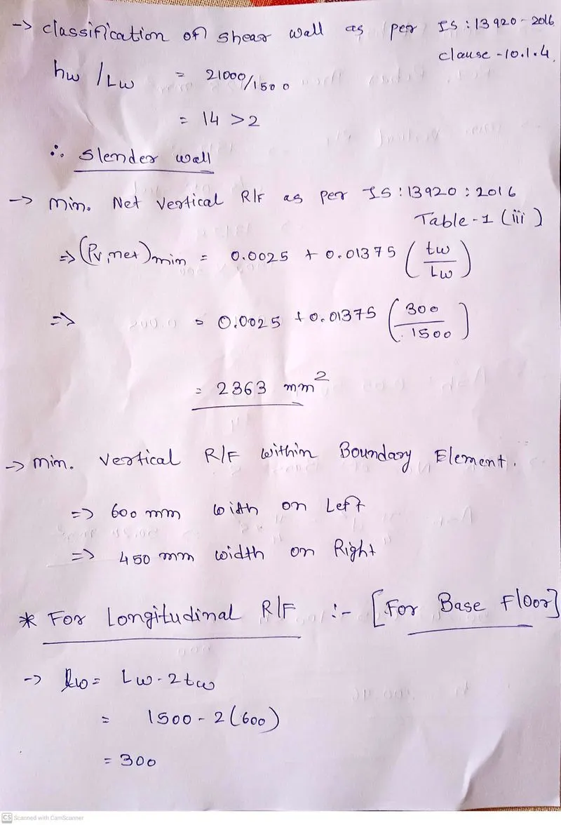
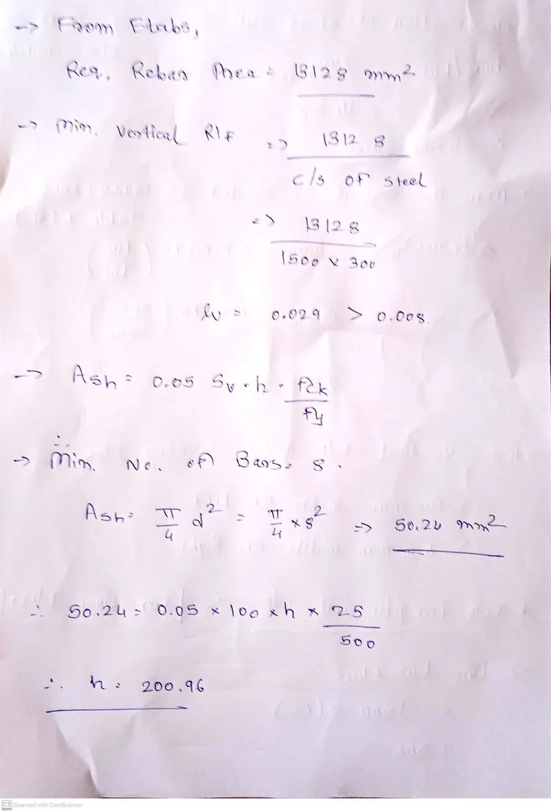
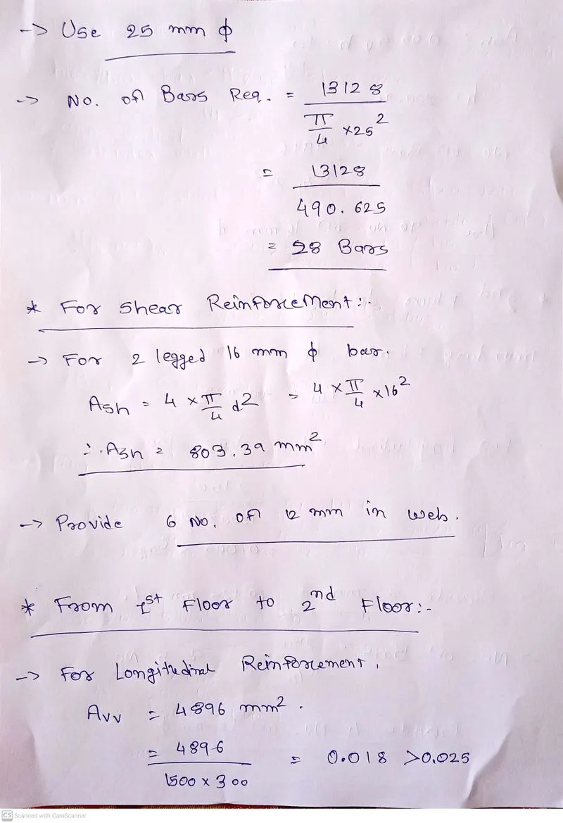
Result :-
- Extracted values of longitudinal steel ratio, boundary element length and shear reinforcing ratio from the design results.
- Provided cross sectional steel arrangement of the shear wall from its base up to terrace, in compliance with provisions of IS 13920 – 2016.
- Provided elevation drawings of the reinforcement details of the shear wall from base up to terrace.