Analysis & Design of RCC shear walls in the model using ETABS
Answer-
Aim of challange -
- To know the design of RC Shear wallusing ETABS analysis
- To know the basics of shear wall reinforcement detailing with respect to indian standards.
- To ensure the Ductility reinforcement required by IS-13920-2016 has satisfied in reinforcement drawing.
Introduction of Shear Wall- Shear wall is a vertical element of a seismic force resisting system that is designed in structure to resist a plane lateral forces, like wind and seismic loads.
Procedure -
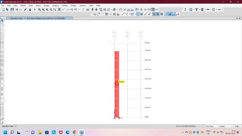
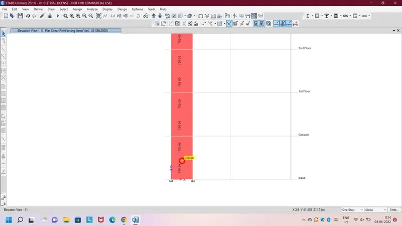
Download file -select all storey-select shear wall grid A-11-right click - show selected object-View elevation along grid A-11-run the analysis-see max and min deflection value-go to option shear wall design - show longitudinal reinforcement-display design info-see shear reiforcement require - go to peir edge or boundry element-see boundry reinforcment.
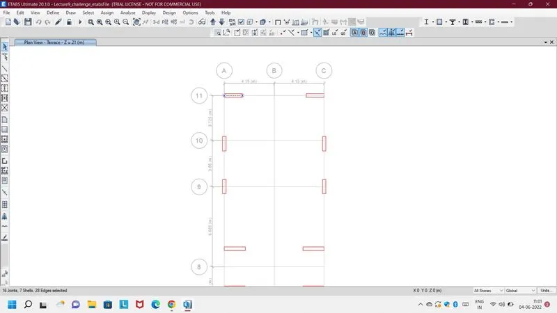
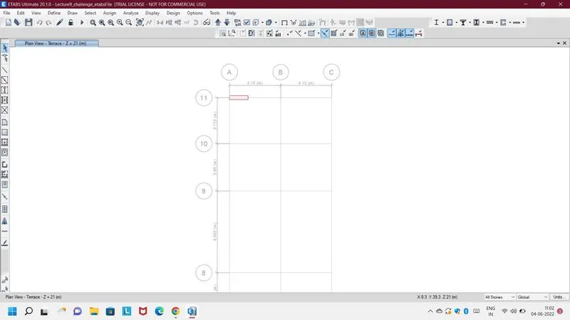
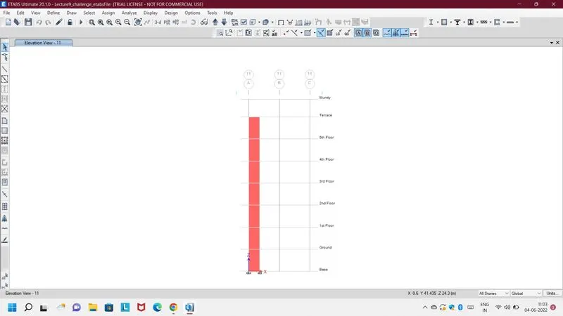
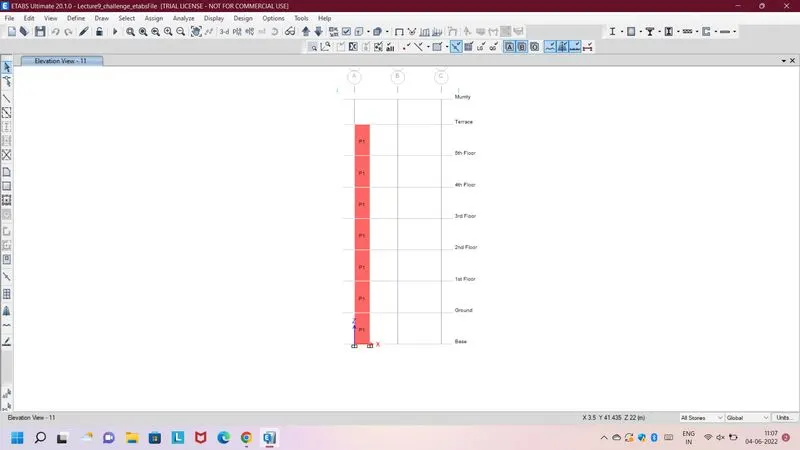
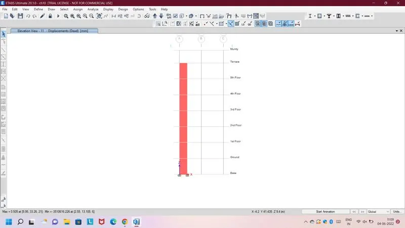
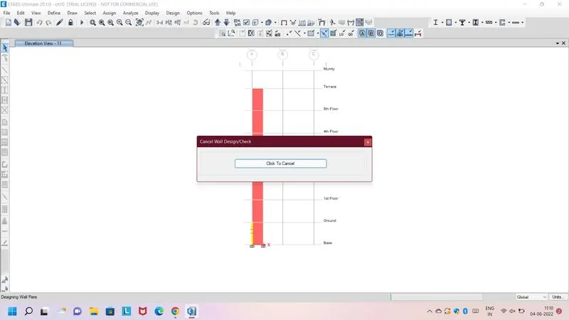
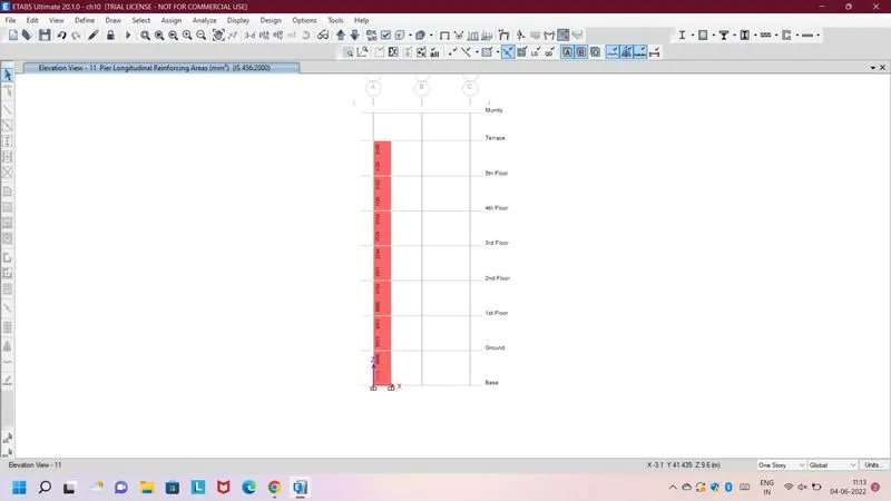
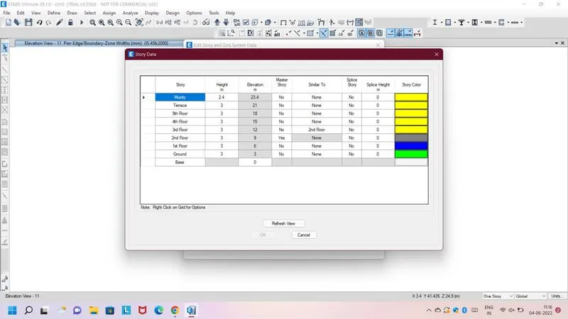
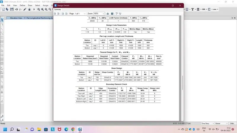
Values of longitudinal steel ratio, boundary element length and shear reinforcing ratio from the design results-
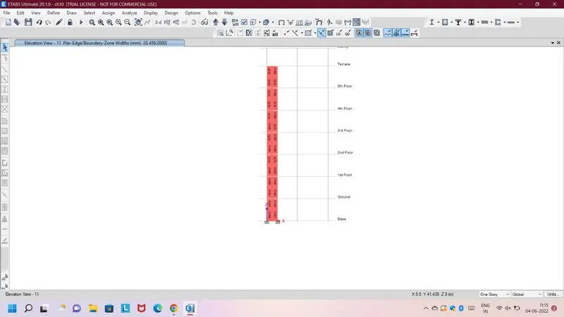
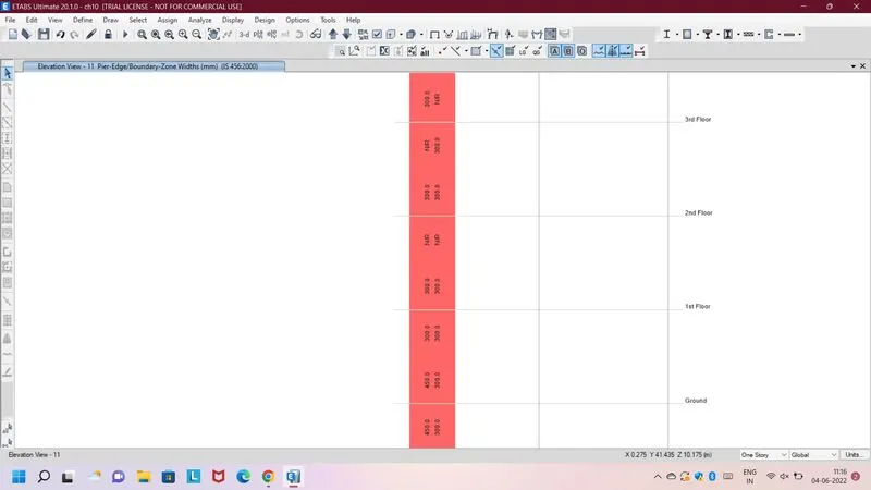
Detailing rule for shear wall-
- Minimum reinforcement for shirankage & temperature
- ultimate limit state design rebar reqirement
- Ductlity rebar requirement
Which is greater in above, should be draw in Shear wall.
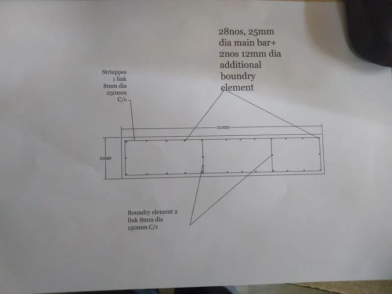
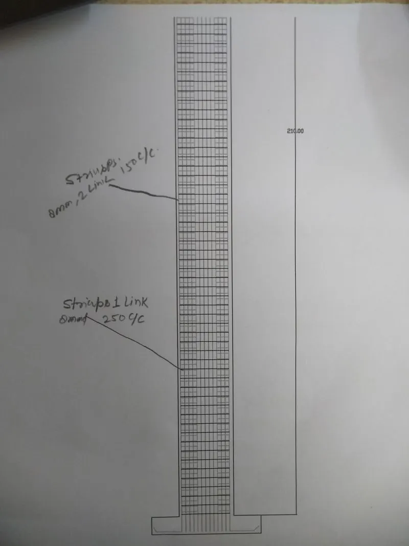
Reinforcement Detailing as per IS code-
Classification of shear wall as per IS 13920-2016 clause 10.1.4-
shear wall classification depends on wall overall height & wall length ratio-
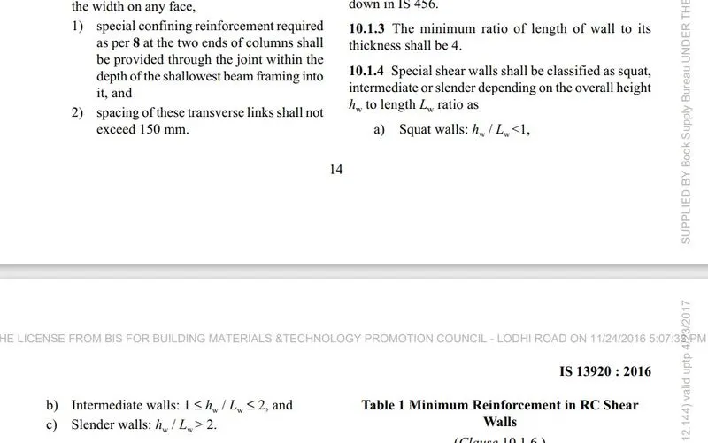
Result - Shear wall A-11, Overall height = 21000mm & Length =1500mm
So Ratio of height & Length =21000/1500=14 it is greater then 2 so this wall is slender wall.
As per IS 13920-2016 Table -1
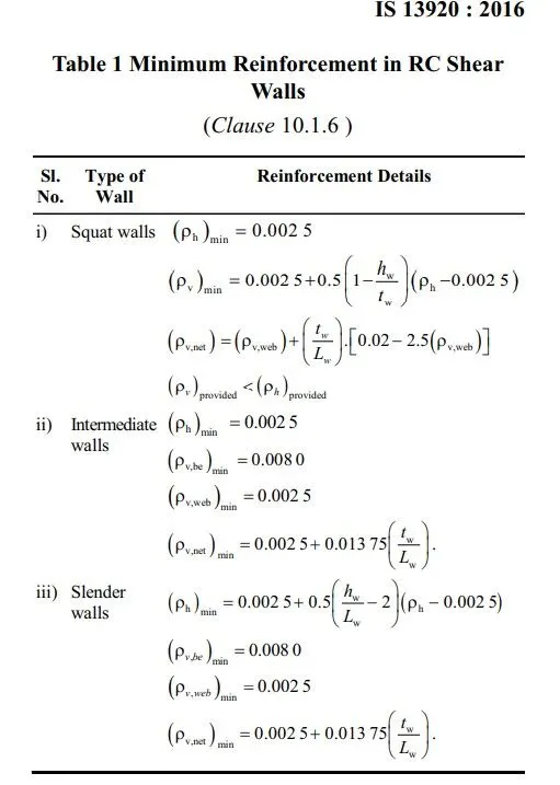
Result-
Minimum net vertical r/f = 0.0025+0.01375X(300/1500) = 2363 sqmm.
Minimum Vertical r/f = 0.8% X 600 X300 = 1440 sqmm. (where 600 is width of boundry element Left)
Minimum Vertical r/f = 0.8% X 450 X300 = 1080 sqmm. (where 450 is width of boundry element Right)
Minimum Horizontel r/f = 0.025+0.5X((2100/1000)-2)X(0.0025-0.0025) =0.025 %
so =0.025% X 300X1000 = 750 sqmm / m
Minimum dia of bar for shear wall as per 13920-2016 clause 10.1.8-

Result- in this = 300/10=30 mm so here we are used 25 mm dia bar due to 30 mm dia bar is not going production.
Confining r/f Spacing for boundry element as per IS 13920-2016 clause-10.4.4-
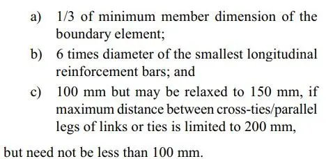
As per a) = 300/3 =100 mm, b) = 6x25= 150
So here we choose 150 mm spacing c/c
Confining r/f for boundry element as per IS 13920-2016 clause-10.4.4-
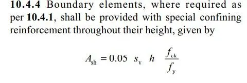
Result- Ash= 0.05x150x1000x(25/415) = 451.8 sq mm
here in my Etabs Result is 450 so this is ok.
Detail sketch of Reinforcement-