Analysis & Design of RCC shear walls in the model using ETABS
AIM: -
The aim for this challenge is to run the analysis and to design the RCC shear walls. And to extract the values of longitudinal steel ratio, boundary element length and the shear reinforcement ratio from the design results.
Procedure: -
- Open the ETABS software and open the attached file given in the question.
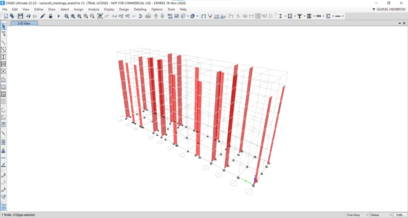
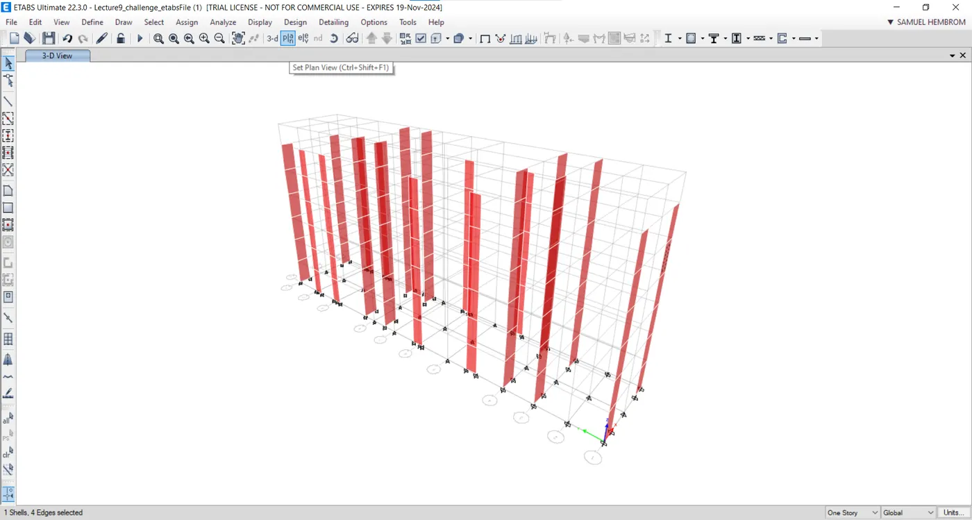
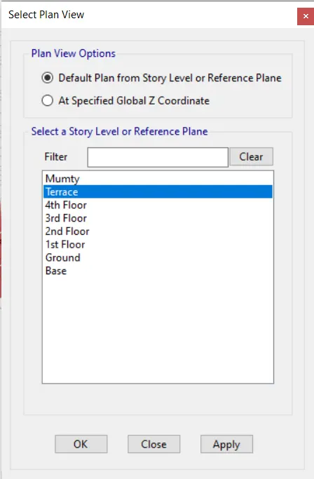
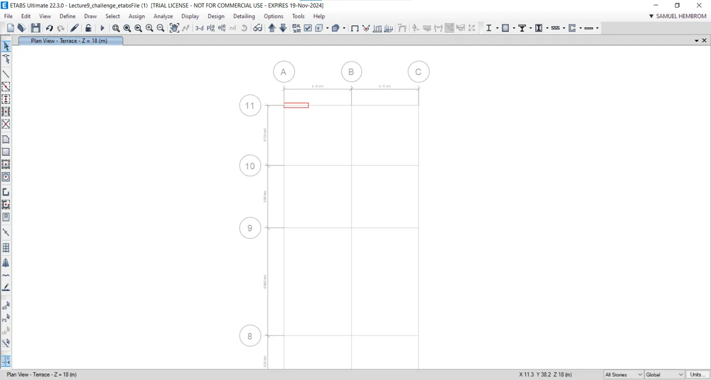
- Set the view to Plan at terrace level using the plan icon on the icon toolbar ribbon as shown in image below.
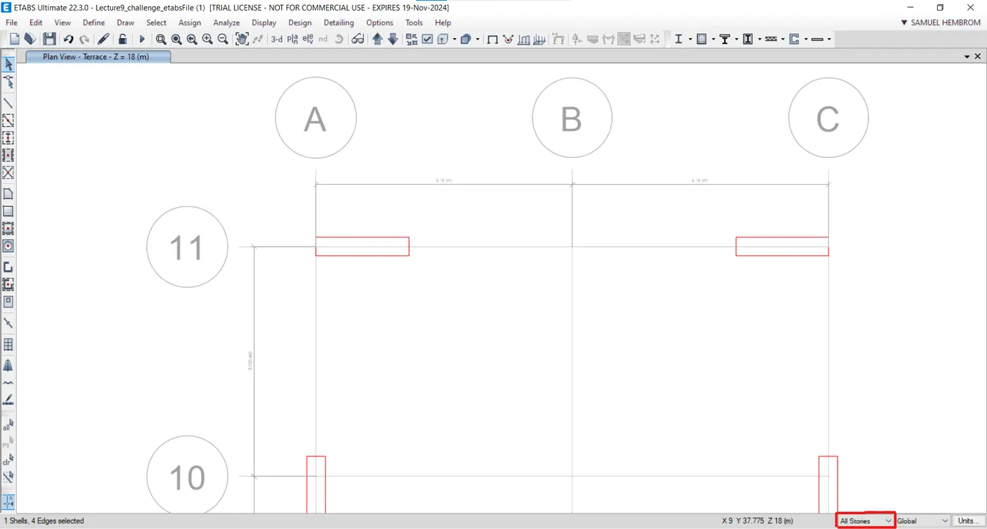
- As given in the question we have to design for the shear wall at the intersection of grids "A" and "11".
- Select "All stories" option form the drop-down menu in the bottom right corner of the screen as shown in image below.
- Next select the shear wall at the intersection and right click on the screen and from the appeared menu choose "show selected objects only" option from the menu.
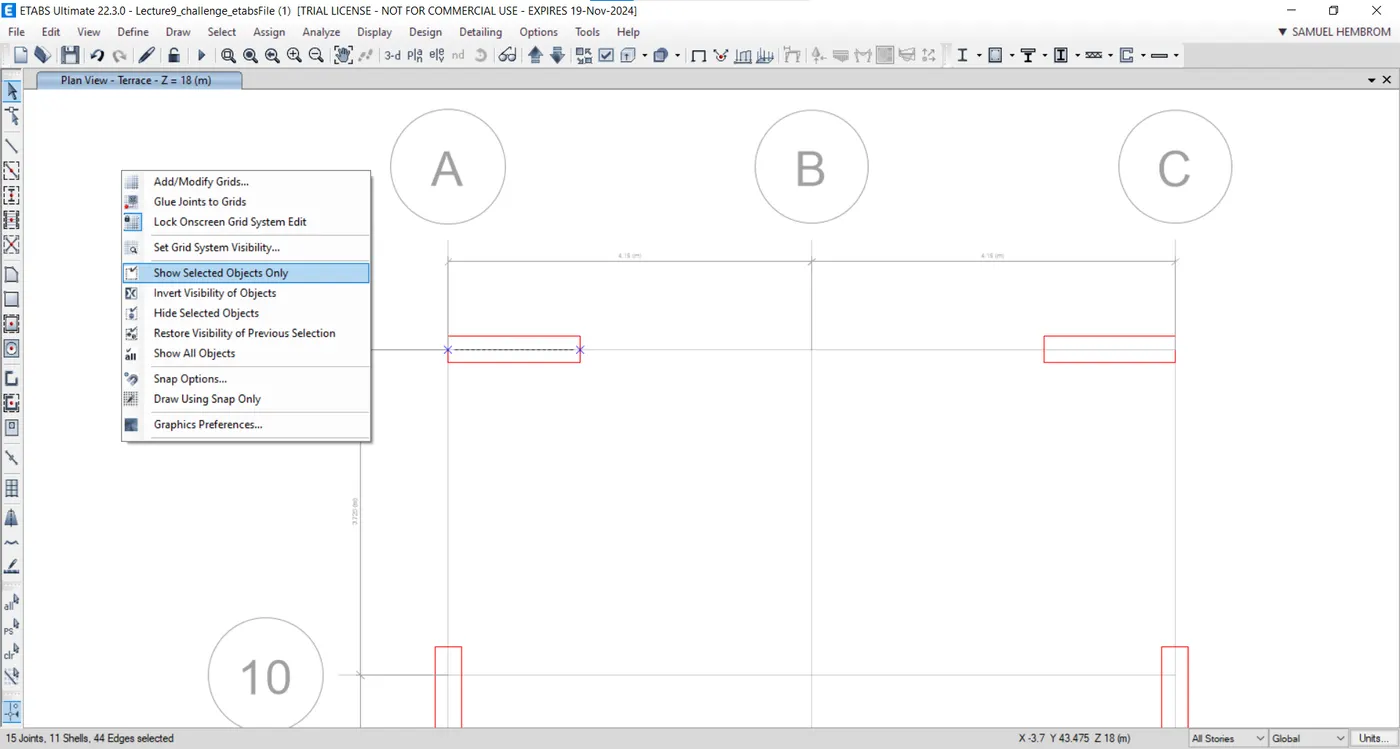
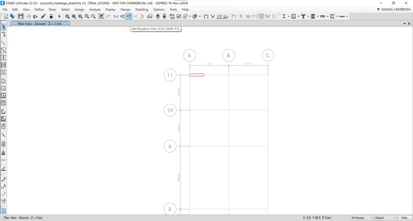
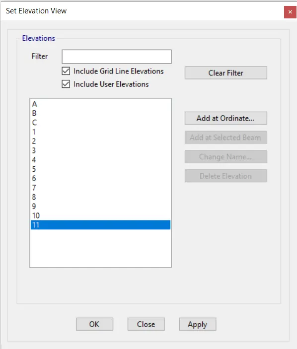
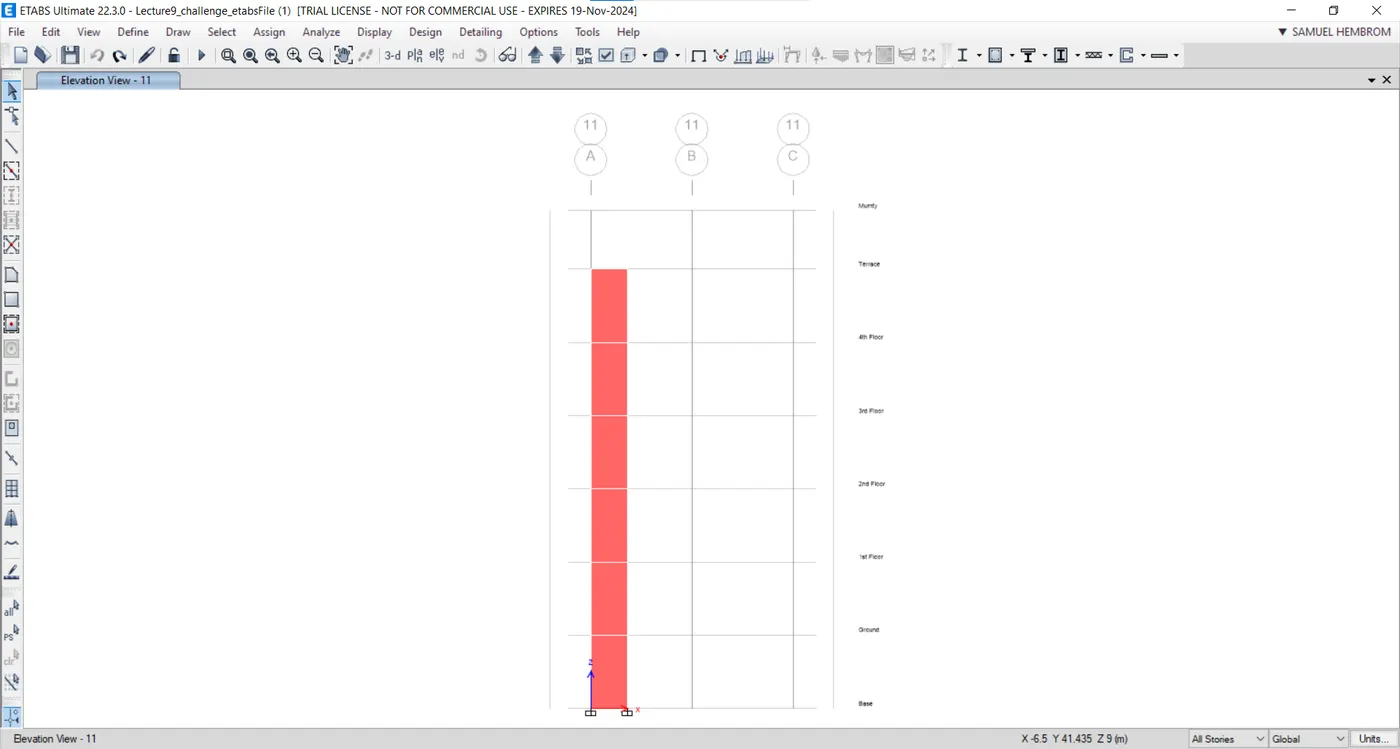
- To see the elevation view change the view to elevation along grid 11 so it becomes easy to extract information for boundary element, longitudinal reinforcement and shear reinforcement.
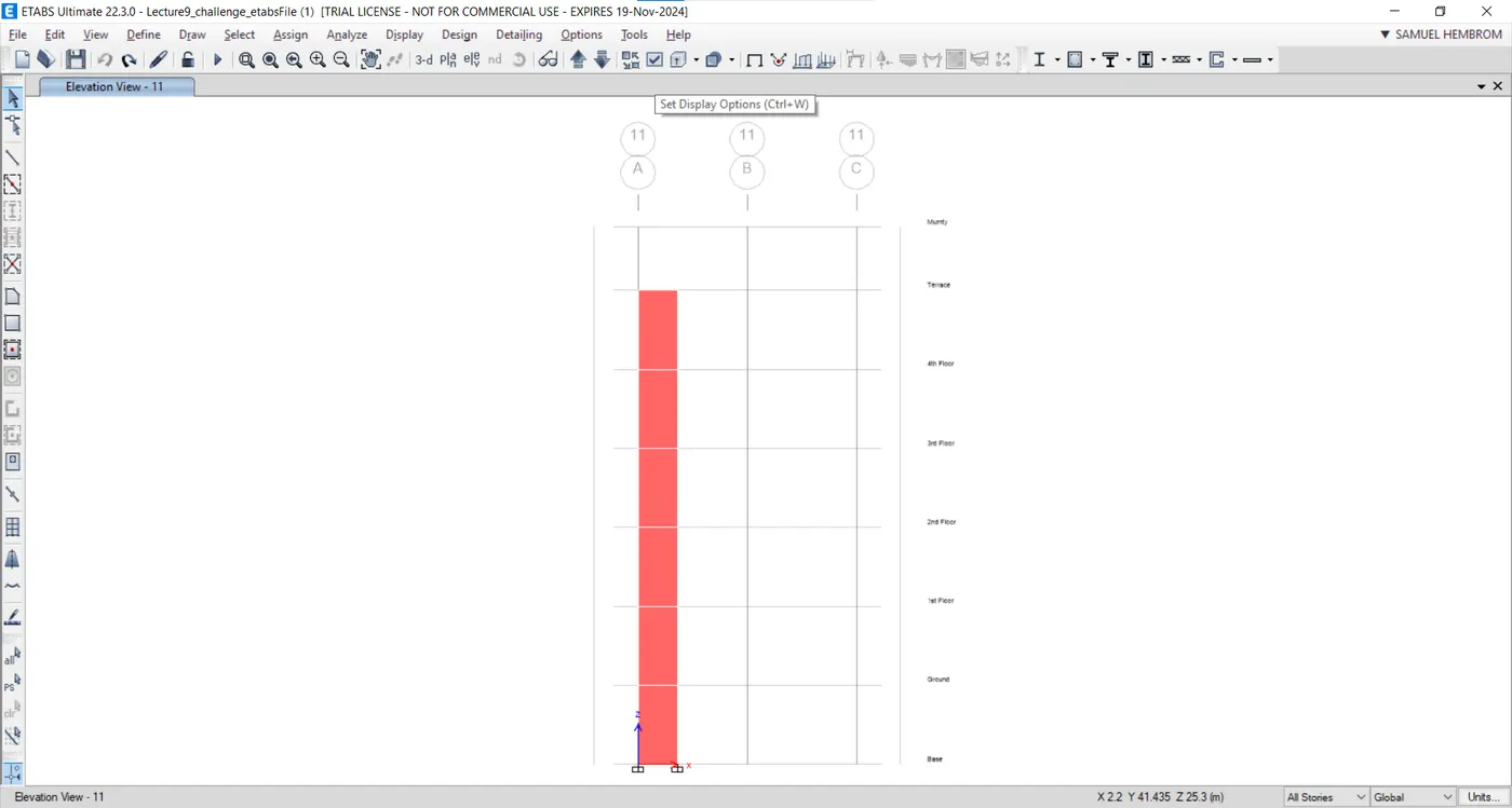
- To ensure, whether the piers are assigned or not go to "Set Display Option" in the icon's toolbar.
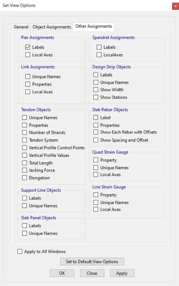
- In the next box go to "Other Assignment" section and under the "Pier Assignment" click on "Lable" check box.
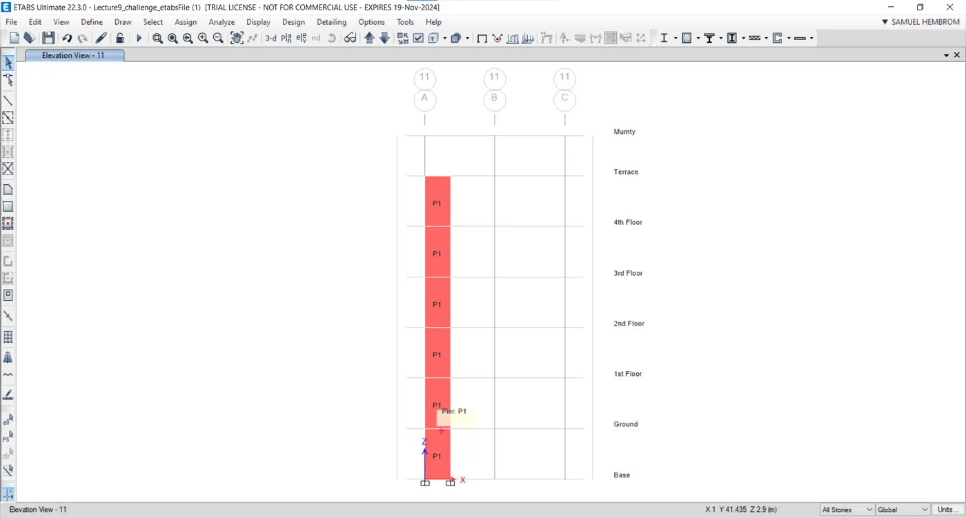
- After that just run the analysis by clicking on the "Play" button in the icon's toolbar as shown in image below.
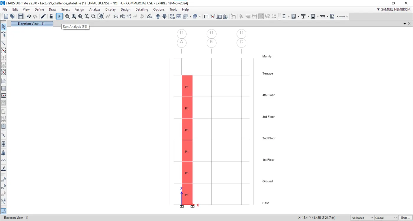
- Deflection values can be seen in the status bar so it can be said that analysis is complete.
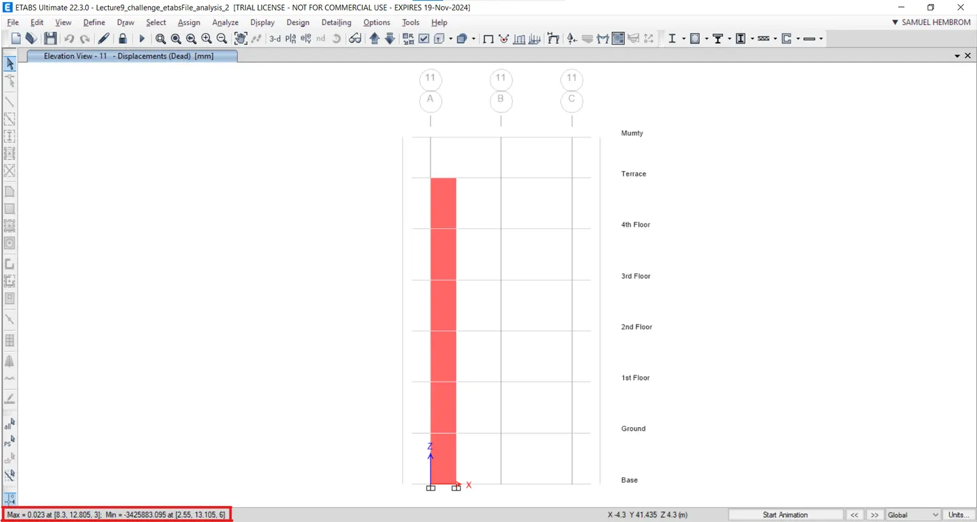
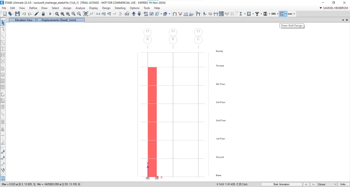
- In the icon's toolbar there is a separate button for "Shear Wall Design" just click on it.
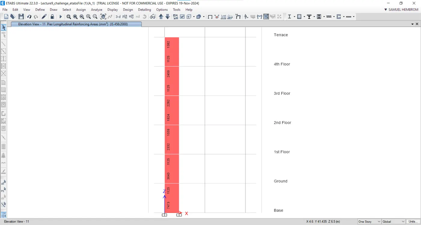
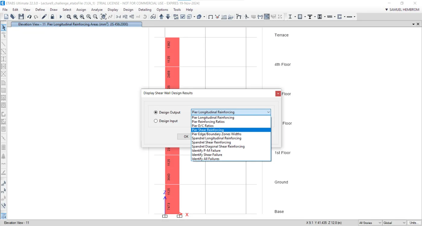
- Following is the result for "Pier Longitudinal Reinforcing Area".
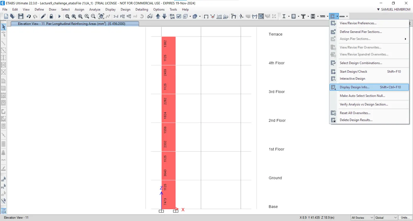
- For further design info click on the downward arrow button next to the "Design Shear Wall" and from the drop-down menu select "Display Design info".
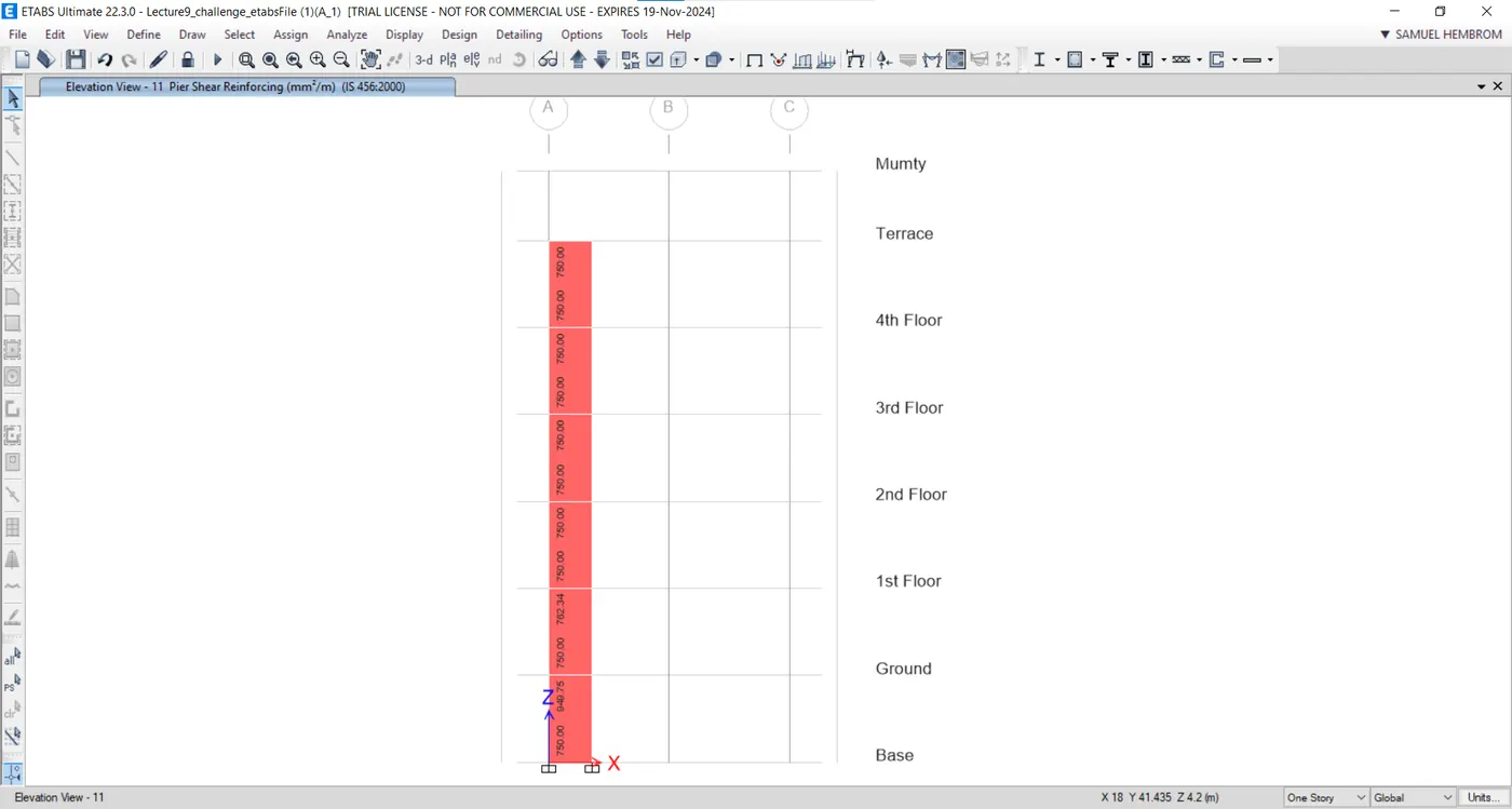
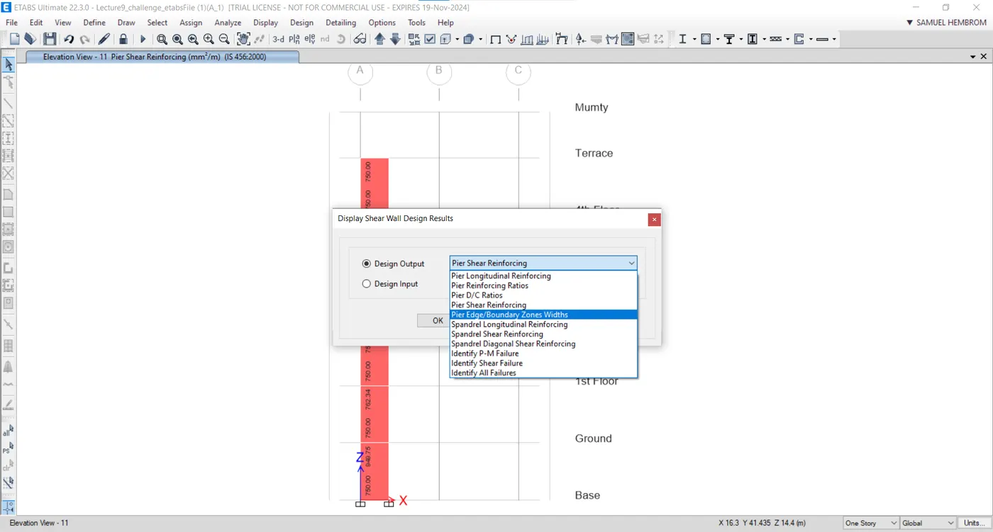
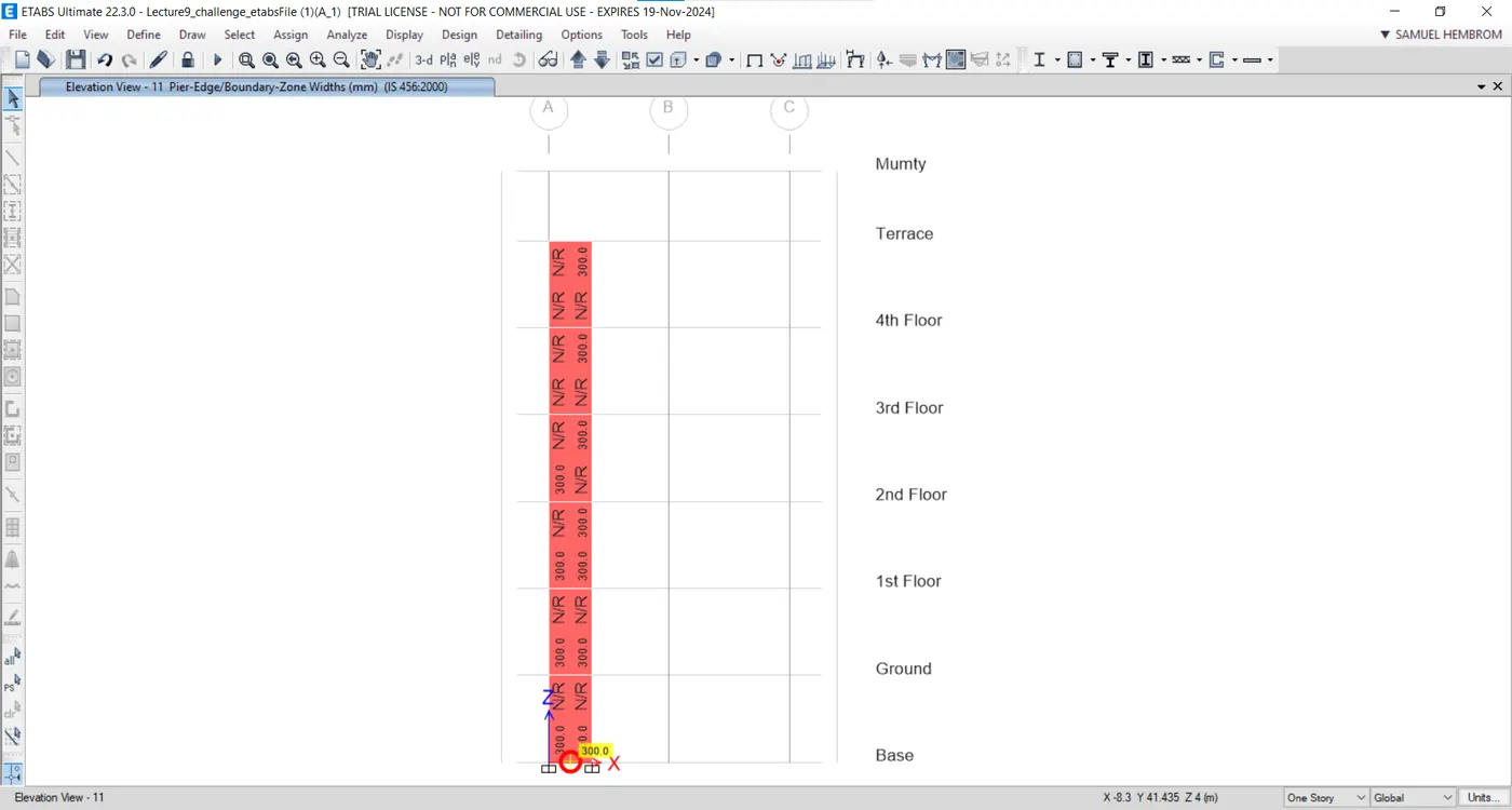
- In the next dialogue box select "Peir Shear Reinforcing" and "Peir Edge/Boundary Zone Width" one by one to see horizontal reinforcing details and boundary element details.
- Vertical Reinforcement Details
- Horizontal Reinforcement Details
- Boundary Reinforcement Details
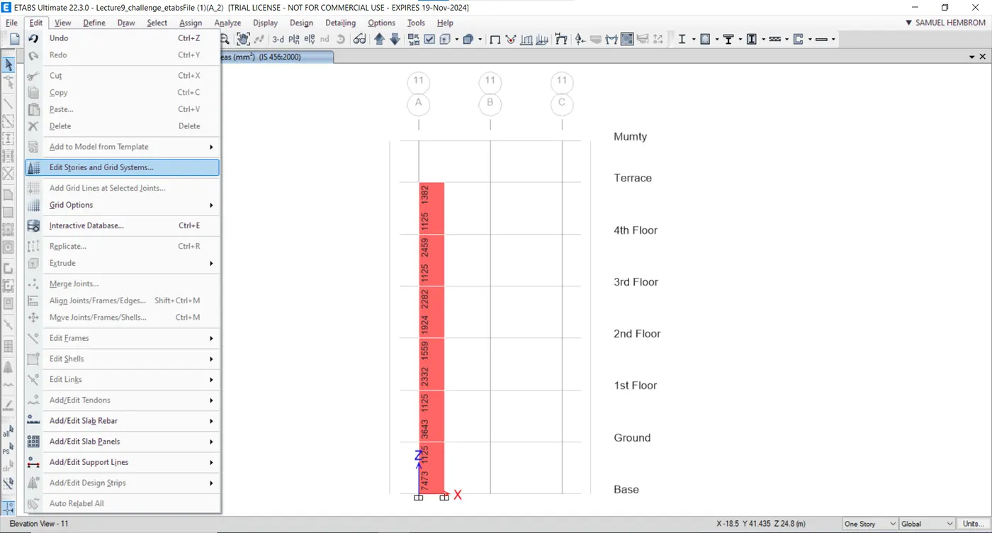
- To know the elevation details of the model, go to Edit --> Edit Stories and Grid System.
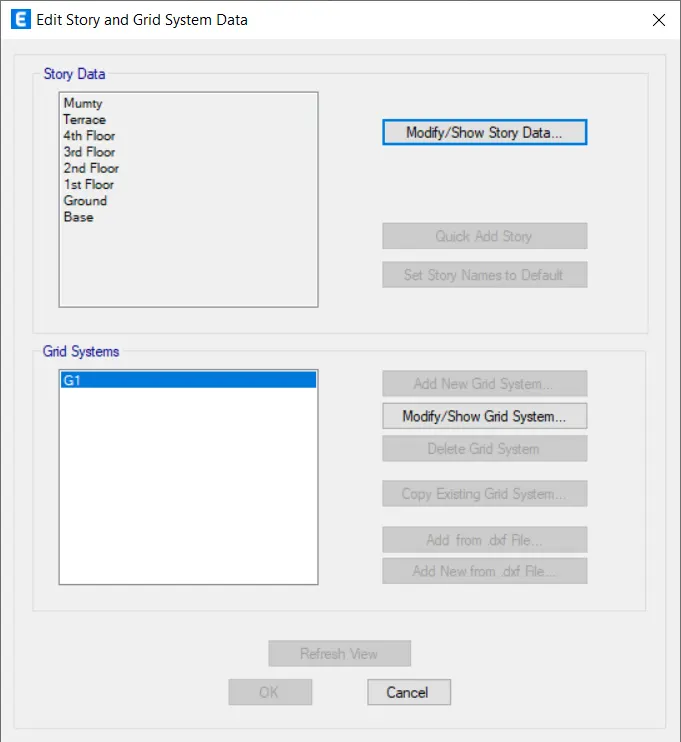
- In the next dialogue box click on the "Modify/Show story Data" button.
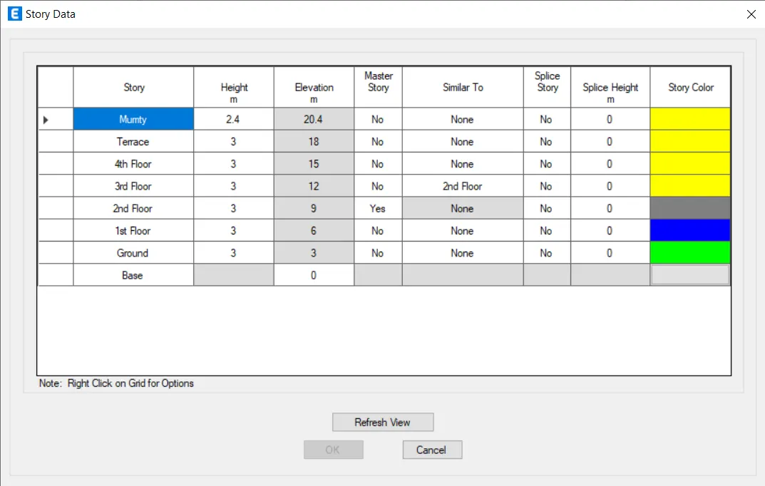
- To draw the elevation of the shear wall we need to know the story data as shown in image below.
DETAILED CALCULATIONS FOR THE SHEAR WALLS: -
- The detailed procedure of detailing the shear reinforcement bar in the shear wall is explained below with brief detailing.
SECTION CLASSIFICATION: -
- So, the very first step that we need to check is the geometrical properties of the wall like the thickness of the wall, the length to thickness ratio, the type of shear wall, diameter of the rebar etc, and whether these properties are within the limit or not as per IS Code 13920:2016.
THICKNESS OF THE WALL: -
- According to the IS 13920:2016 clause no. 10.1.2, the minimum allowable thickness of the shear wall should not be less than 150mm.
- But in our case the thickness of the shear wall given is 300mm which is greater than the 150mm suggested by the IS Code 13920:2016. Hence our design is safe.
LENGTH TO THICKNESS RATIO: -
- According to the IS 13920:2016, clause 10.1.3, the length to thickness ratio must be equal or greater than 4.
- So, the length of our shear wall is 1500mm.
- Thickness of our shear wall is 300mm.
- Therefore, the length to thickness ratio =Length/Width = 1500/300 =5
- Since, 5>4, Hence ok.
SHEAR WALL TYPE: -
- According to the IS 13920:2016, Clause 10.1.4, suggest that we have three different types of the shear wall based on their geometrical properties and these walls are listed below.
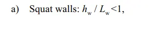

- So, in our case, we have the height of the wall (hw) = 18000 mm.
- and the length of the wall (Lw) = 1500 mm.
- Therefore, hw/Lw = 18000/1500 = 12
- Hence, hw/Lw = 12 > 2.
- The fraction here is greater than 2, hence OK.
REINFORCEMENT LAYER: -
- So, a/c to IS 13920:2016, clause 10.1.7, the reinforcement shall be provided along with both faces of the wall thickness must be greater than 200mm.
- So, in this case we have shear wall thickness of 300mm which is greater than 200mm, so we have to provide the rebars along with both faces of the wall.
DIAMETER OF THE REBAR: -
- A/C to the IS 13920:2016, clause 10.1.8, states that the largest diameter of the longitudinal bar shall not exceed 1/10th of its thickness.
- So, in our case the thickness of wall = 300mm.
- Therefore, 1/10th of the thickness = (1/10) * 300 =30mm.
- Which means, we cannot use any bar that is exceeding 30mm diameter value. So, we will be using the 25mm diameter bar in our case because we cannot use more than the 30mm diameter.
DETAILED CALCULATION: -
Minimum vertical reinforcement as per IS - 13920:2016 Table - 1 (iii)
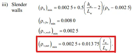
- = 0.0025 + 0.01375 (300/1500)
= 0.00525
- Next, we need to multiply the above ratio to crossectional area i.e. 300 * 1500= 450000 mm^2.
- Therefore, Net vertical reinforcement = 0.00525 * 450000 = 2362.5 mm^2 = 2363 mm^2.
Minimum Vertical Reinforcement within boundary element Table-1 (iii)
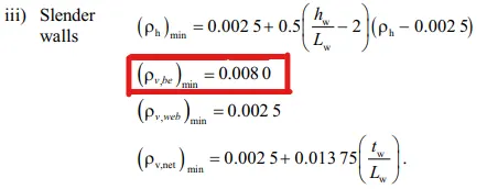
- = 0.0080
- Next, we need to multiply the above ratio to crossectional area i.e. 300 * 300 = 90000 mm^2.
- Therefore, Net vertical reinforcement within boundary element = 0.008 * 90000 = 720 mm^2 on left (300mm width boundary element)
- Similarly, Net vertical reinforcement within boundary element = 0.008 * 90000 = 720 mm^2 on right (300mm width boundary element)
- Minimum horizontal reinforcement in shear wall as per IS - 13920:2016 Table-1 (iii): -
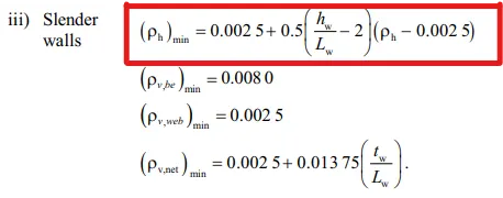
- Where, ph can be calculated as
ph= 750(shear reinforcement from ETABS result)/ (300*1000) = 0.0025, hw = 21000, Lw = 1500
(ph)min = 0.0025 + 0.5 (21/15 - 2) * 0
(ph)min = 0.0025 which is the same 750 mm^2/m.
Maximum spacing of vertical or horizontal reinforcement as per IS 13920 :2016 clause 10.1.9: -
The maximum spacing of vertical or horizontal reinforcement shall not exceed smaller of: -
(i) 1/5th horizontal length Lw of wall = 1/5 * 1500 = 300mm
(ii) 3 times thickness of web of wall = 3 * 300 = 900mm
(iii) 450mm
- From above three values 300 mm is the smallest.
- So, for design convenience I will take spacing as 250mm for vertical and shear reinforcements.
Confining reinforcement spacing for boundary element as per IS 13920 - 2016 clause 10.4.4 : -
(i) 1/3 of minimum member dimension = 300/3 =100mm
(ii) 6 times smallest main rebar = 6 * 25 = 150mm
(iii) 150 mm permissible if vertical bars are spaced at maximum 200mm
- maximum spacing of confining reinforcement in boundary element 150 mm.
- Confining reinforcement within boundary element as per IS-13920-2016 clause 10.4.4
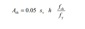
Sv = 150mm, h = 1000mm
Ash = 452 mm^2
RESULT: -
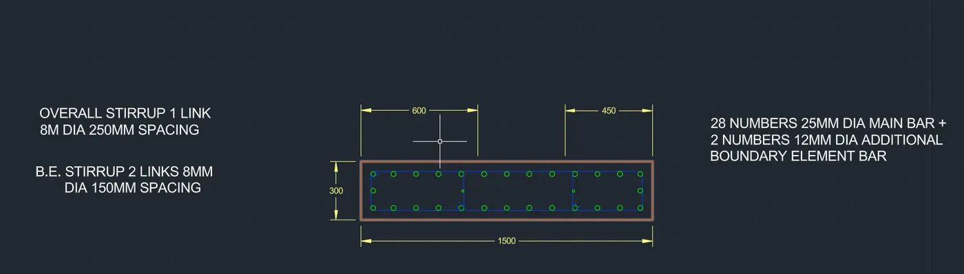
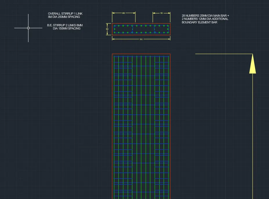
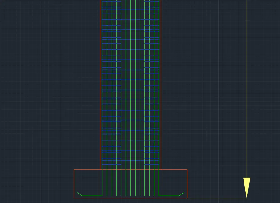
Following is the crossectional and elevation view of the shear wall.