Analysis & Design of RCC shear walls in the model using ETABS
The below is the given plan which comprises the shear walls entirely instead of the columns.
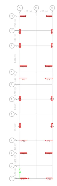
And this is the shear wall which is to be designed.

And we check weather its labelled or not using the display settings.

Now,we take the required values from the ETABS Software,where basing upon these we design the reinforcement.
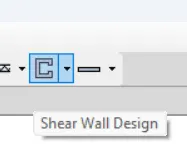
For us to get the Longitudinal Reinforcement,we initially go to Shear Wall Design where we directly get the Longitudinal Reinforcement.
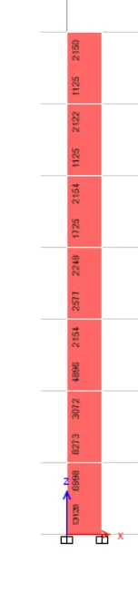
Then to get the Shear Reinforcement,we go to Shear Wall Design>Display Design Info> Pier Shear Reinforcement.
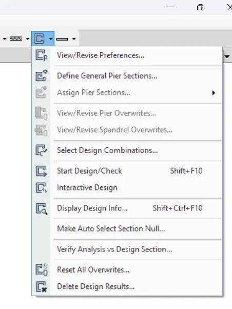
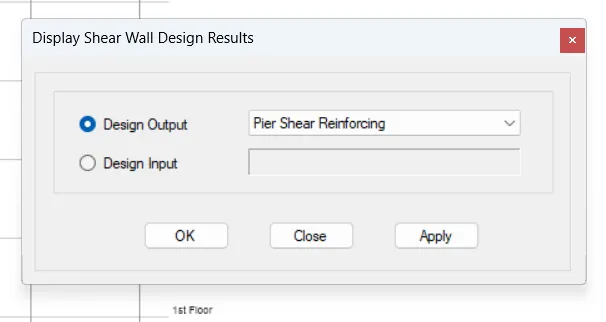

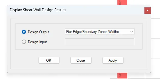
The to get the Boundary Edge,we go to Shear Wall Design>Display Design Info>Pier Edge.

In the same manner,we do take the values of the Pier Longitudinal Reinforcing Ratio by going to Shear Wall Design>Display Design Info>Pier Longitudinal Reinforcing Ratio.
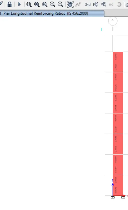
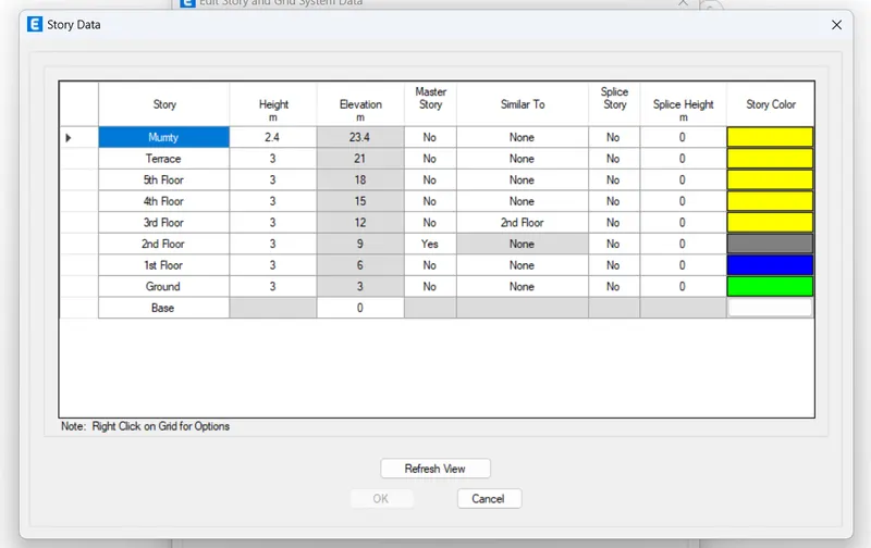
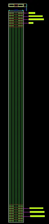
And the below are the elevation details of the shear wall.
Designing of Shear Wall as per the IS 13920-2016
1.Type of Wall
It is the first step to be done,where we have to know the type of wall,where most of the walls we go are slender only.
As per clause 10.1.4,
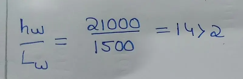
So,it's slender wall.
2.Minimum Net Vertical Reinforcement
We then calculate the minimum vertical reinforcement required for the shear wall.
We do this step in order to just to know the minimum requirement only where we actually use the ETABS derived value only but to check weather that value had overcrossed then code value.
As per Table.1,
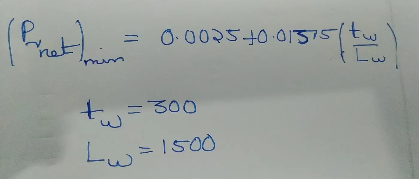
The above resultant is the value of the ratio where we multiply it with the top cross sectional area to get the steel requirement.
So,
Minimum Net Vertical Reinforcement=[0.0025+0.01375(300/1500)]{1500X300}=2362.5 sq mm
3.Minimum Vertical Reinforcement in Boundary Edge
This is a step rather than for the calculation of the steel requirement,here we check weather the sufficient steel is provided in the boundary limits.
As per Table.1,
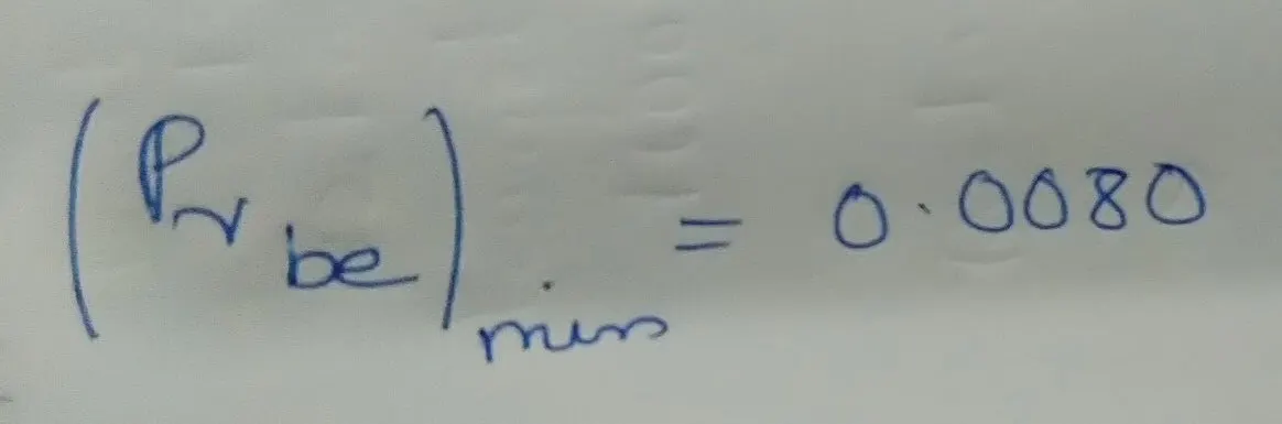
This is the value where we multiply it with the BE length and thickness of the wall.
Here,we even though have different values for each floor on both the sides,we select only the one highest value where we proceed with that to do the calculations.
Here,we only choose one value as it is done practically to make the work easier,to avoid the confusion among the workers and to avoid mistakes and for the safety purposes.
The,we choose BE as 600 mm.
So,
Minimum Vertical Reinforcement in Boundary Edge=0.0080X300X600=1440 sq mm
4.Minimum Horizontal Reinforcement
Here,we calculate the required horizontal requirement of steel.
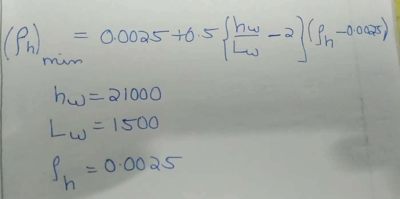
The third value is the Pier Longitudinal Reinforcing Ratio to be brought from the ETABS software,where we use the lowest value of all the available values.
So,
Minimum Horizontal Reinforcement=0.0025+0.5((21000/1500)-2)(0.0025-0.0025)=0.0025=>0.0025X300X1000=750 sq mm
5.Maximum Diameter of Rebar
As per clause 10.1.8,we calculate the maximum diameter of the bar to be used,basing on the thickness of the wall.
1/10X300=30 mm
So,we use the 30 mm dia bar.
6.Spacing of Confining Reinforcement
- 1/3X300=100 mm
- 6X30=180 mm
So,we go for the maximum spacing of 150 mm,as the bigger of the above is the maximum spacing value.
7.Confining Reinforcement with in Boundary Edge
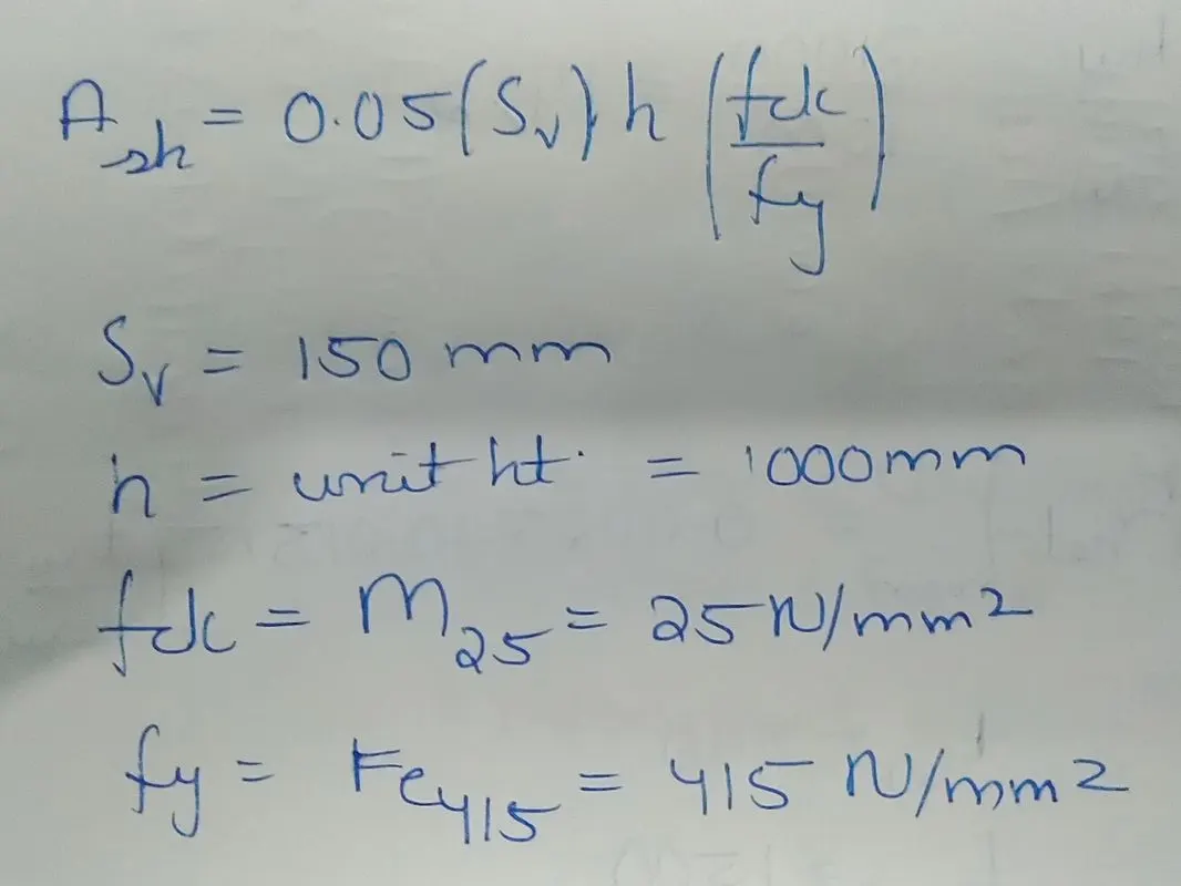
As per clause 10.4.4,
So,
Confinement Reinforcement in Boundary Edge=0.05X150X1000X(25/415)=452 sq mm
Desiging of Shear Wall as per ETABS
1.Longitudinal Reinforcement
As decided,we do use the 30 mm dia bars as the longitudinal reinforcement.
Here,as per the ETABS,we do consider the longitudinal steel area as 13128 sq mm,though the value decreases as we go above,but we do use the same value for few reasons such,using the same steel area for all the floors will avoid the confusion among the workers,will make the work faster and more over it could be additional safety for the structure.
The,area of 30 mm dia steel bar=3.14X15X15=706.5 sq mm
No. of bars=13128/706.5=18.5=>19=>20@150 mm c/c
We round it off to the even no. for the symmetry purpose.
Then,
As per the arrangement,we will be having 8 bars in the Boundary Edge Zone,so,area of the longitudinal reinforcement in the zone be 8X706.5=5652 sq mm>1440 sq mm.
2.Horizontal Reinforcement
From the Code aswell as from ETABS,we have got the same value of Horizontal Reinforcement=750 sq mm.
So,we continue by using the 12 mm dia bars,so,area of bar=3.14X6X6=113.04 sq mm.
Then,no. of bars on 2 sides=750/(2X113.04)=3.3=>4 bars@12 mm dia
Spacing of Bars=1000/4=250 mm
3.Stirrups
Here,we provide the stirrups only for the Boundary Edge Longitudinal Reinforcement,and for this we use 8 mm dia bars,which do have the area of 50.24 sq mm.
No. of Stirrups=452/(2X50.24)=4.49=>5 stirrups
Spacing of Stirrups=1000/5=200 mm>150 mm as decided before.
But we go with 125 mm,so that we can place them between the horizontal bars equally.
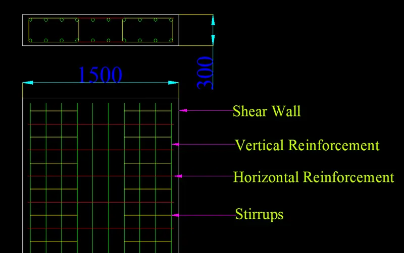
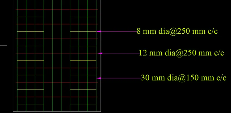
Here,we use the Concrete@M25 and Steel@Fe415.
We leave a gap of 75 mm on both the sides for the Vertical Reinforcement.