Analysis & Design of RCC shear walls in the model using ETABS
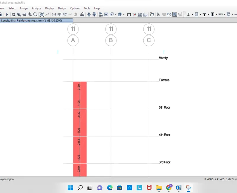
1.Aim: To design the longitudinal reinforcement, boundary element length and shear reinforcement of the shear wall in the particular grid position using the E tabs is provided.
Procedure:
- shear wall is a RCC structural component which is constructed in the building to with stand the lateral force caused by the ground due to the earthquake.
- When the building is in the eart quake it is better to design the shear walls and by designing the shear walls the column units can be eliminated and the shear walls are constructed from the foundation to the terrace with the required longitudinal and shear reinforcement and the boundary width is specified and the reinforcement of the boundary width zone is provided with out any changes.
- The shear walls are also called as piers of the building and the reinforcement is denoted as pier longitudinal reinforcing and pier shear reinforcement.
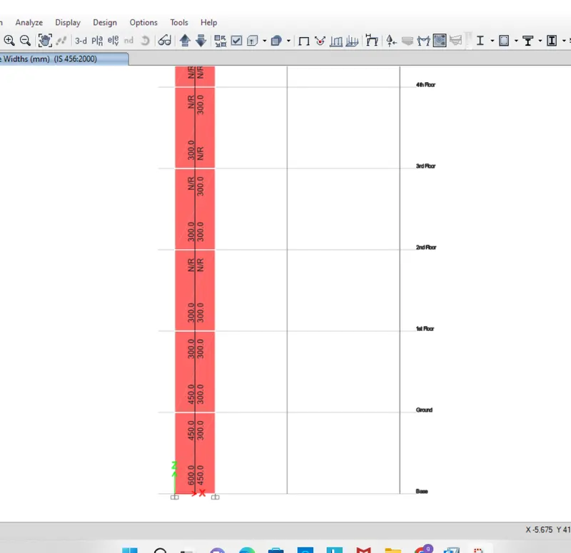
- The boundary edge width may change according to the storey height and the loading condition. The boundary edge width may change.The boundary width may be considered as the higher value among the both sides for the safe and secure condition of the building.
Detail guideline for the shear wall:
- The shear wall should be provided with the minimum reinforcement for both longitudinally and in the shear direction for the shrinkage and the temparature.
- The shear wall designed should satisfy the ultimate limit state design.
- The shear wall when subjected to the latearl force it shouldnot fail due to the ductile force and it will provide the ductility rebars on all the sides.
- To design the longitudinal reinforcement the guilde lines from the IS 13920-2016 cl10.1.4. More over in most of the cases between the RC wall and shear wall, the shear walls are designed with the codee IS 13920-2016. The basic difference between the shear and the RC walls is that the RC walls are provided with the reinforcement will resist the gravity loads on the building where as the shear walls are designed mainly to resist the lateral force caused by the ground during the earth quake.
- According to the IS13920-2016 cl10.1.4 the shear wall is classified based on the ratio between the height of the wall `hundersetw`and length of the wall `lundersetw`. and the ratio between the height and length of the wall is greater than 2 then the wall is designed as slender wall, i.e `hundersetwdiv(lundersetw`for the given wall the ratio is 21000/1500=14>2 so the given wall is to be designed as a slender wall.
- Based on the classification the reinforcement os provided for the shear wall, minimum net vertical reinforcemet is obtained from the IS13920 table 1(iii) and it is 0.0025+0.1375(`TundersetwdivLundersetw`)and the value is 2363`mmoverset2`
- Minimum vertical reinforcement with in the boundary element is obtained from the table 1(iii). Based on the width of the boundary element the reinforcement may incraese or decrease.
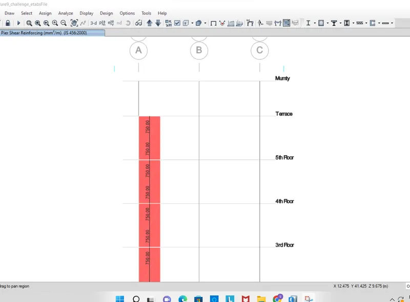
- After the evaluation of the longitudinal reinforcement shear reinforcement is derived from the code IS 13920-2016 table1(iii). `rhoundersethmin`=0.0025+0.5(`hundersetw divlundersetw`-2)(`rhounderseth`-0.0025) and here `rhounderseth`is the horizontal reinforcement ratio obtained from the E tabs result.
`rhounderseth`=750/300*1000=0.0025
`rhoundersethmin`=0.0025
Here both are same and the shear reinforcement value is 750`mmunderset2`/m.
- Maximum thickness of the wall as per the code IS13920 -2016 is 1/10th of the thickness of the wall 300/10=30mm.
- The localized concentration of the shear wall is like boundary element and the shear reinforcement for the boundary zone alone is termed as confining reinforcement.The spacing of the reinforcement is based on the conditions in the cl10.4.4 ,
- While designing the shear wall should follow thesatisfy the ductile e failu
1/3 of the minimum of the size of the wall.
6 times of the smallest diameter of the bar.
150mm permissible if vertical bars are spaced at 200mm maximum.
- Based on the reinforcement spacing as per IS 13920-2016 cl 10.4.4
`Aunderset(sh)`=0.05`sundersetv`h`funderset(ck)`/`fundersety`
`Aunderset(sv)`=452`mm overset2`
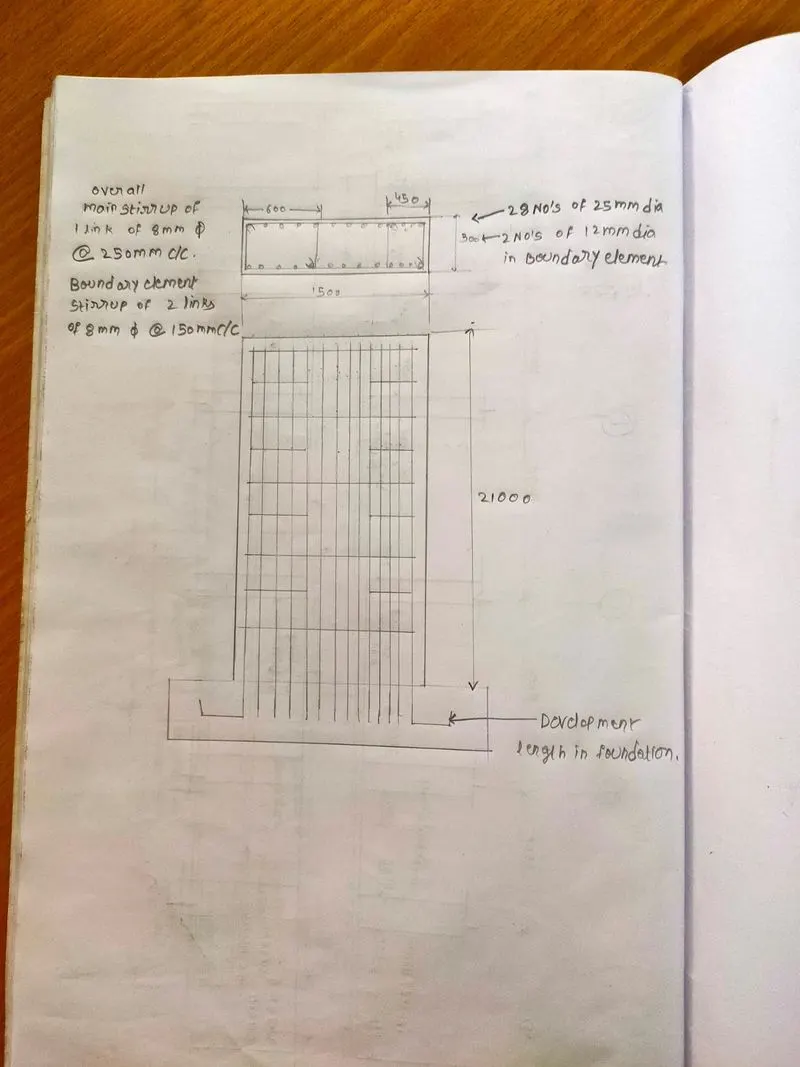
Here 28 nos of the 25 mm diameter are placed and more over two nos of 12mm dia are placed with in the boundary element and if the reinforcment is beyond the limiit then the extrabar need not be considered.
- The main stirrup links are of the 8mm dia for the whole shear wall at the spacing of 250mm where as for the shear reinforcement in the boundary element 8mm dia with a spacing of 150 mm.