Ahmed Body Challenge
Problem Statement:
1. Perform the simulation on half of Ahmed's body since it is symmetric and analyze the plots of velocity and pressure contours.
2. Validate the results from the analytical data.
3. Perform the grid independence test and values for drag and lift for each case.
Introduction:
The flow separation region is a major contribution to the car's drag and lift forces. Hence the determination of the flow separation region in the airflow around the car body is of prime importance to design a car aerodynamically efficient. Due to flow separation regions, it poses severe problems in numerical predictions and experimental values because of the wake region created behind the car. The location at which the flow separates determines the size of the wake flow regions which is proportional to the drag force. Hence correct simulation of the wake flow region is needed for accurate prediction of the drag forces. But in car body is of complex shapes and hence simulation of the exact car body is difficult and requires high computation time and computer hardware requirements. Because of this reason, Ahmed body is chosen which depicts the aerodynamic of a car and helps to predict the flow separation region and size of the wake consequently predicting the drag force.
Drag.
The drag coefficient is a common measure in automotive design as it pertains to aerodynamics. Drag is a force that acts parallel to and in the same direction as the airflow. The drag coefficient of an automobile measures the way the automobile passes through the surrounding air. When automobile companies design a new vehicle they take into consideration the automobile drag coefficient in addition to the other performance characteristics. Aerodynamic drag increases with the square of speed; therefore it becomes critically important at higher speeds. Reducing the drag coefficient in an automobile improves the performance of the vehicle as it pertains to speed and fuel efficiency.
Lift
As the car moves forward the air gets blocked around the frontal area which generates high pressure and hence vertical force is generated which generates a lift force at the front. As the car moves faster more lift force is generated, at a certain velocity lift force is greater than the gravitational force and hence there is lift in the frontal region. The increase in pressure at the front area is because the air gets blocked at the front instead of moving around the body
Geometry.
The Ahmed body depicts the general aerodynamic properties of a car especially in the rear of the car where the slant angle plays a major role in determining the drag and lift forces of the car. In this case, the slant angle is set to 30 degrees.
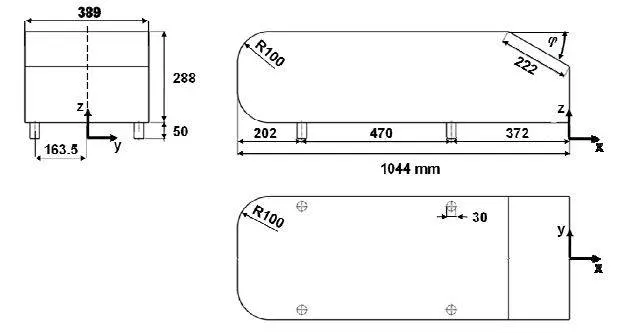
With the above sketch of Ahmed body with dimensions in mm angle in degrees which is modeled and saved in step format and uploaded to ansys fluent space claim.
In space claim, the simulation domain is created as shown in the figure below.
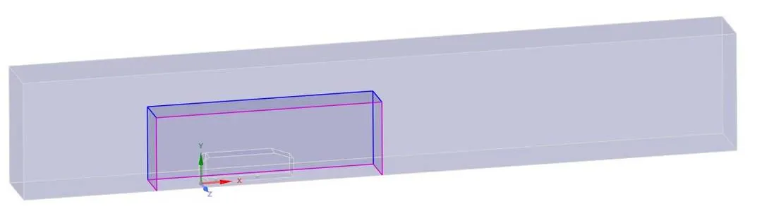
The inner domain is created to accurately capture the wake regions and flow separation points and high-pressure regions generated during the flow of the fluid over the Ahmed body.
Share topology is given to inner domain faces so that there an exchange of information between the outer domain and inner domain.
The Ahmed body is split into half since the given body was symmetric and the symmetry boundary condition is given to the wall of the domain.
Meshing
In the mesh window, the faces of the domain are named so that when the model is opened in the Fluent window boundary conditions are assigned automatically to the faces.
For the outer domain hexagonal mesh is assigned which gives more accurate results when compared to unstructured triangular mesh. This is done using multizone command and assigning the mesh cell size and maximum size of the mesh cell equally to generate a structured hexagonal mesh.
For the inner domain, an unstructured triangular mesh is chosen and smaller mesh size is assigned to capture the boundary layer, flow separation point, and wake regions around the Ahmed body.
Named selection.
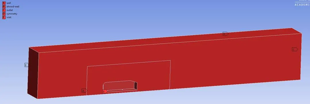
Case 1:- Refined Mesh
Mesh parameters
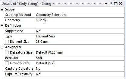
The mesh cell size for the outer domain is 26mm
The mesh cell size for the inner domain is 50mm.
The inflation layer total thickness is 12.5mm.
The number of divisions at the circular edges = 36 divisions.
No. of Elements = 498521
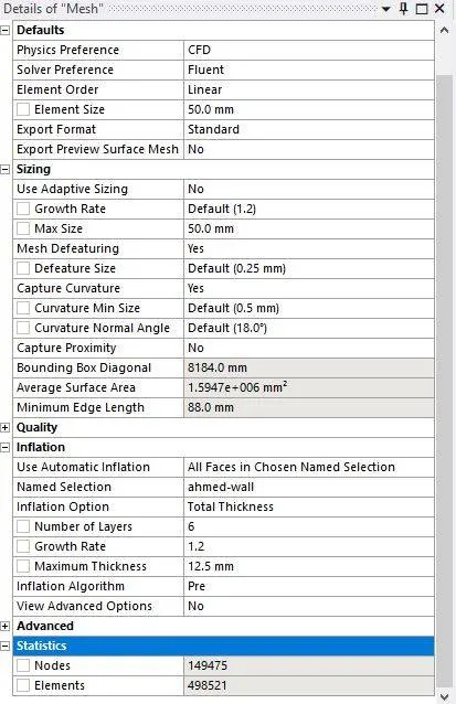
Mesh parameters for the inner domain
Mesh

Setting up Physis for the model.
Calculation of Reynolds number
`Re = (rho.v^2.D_h)/(mu)`
Where `D_h` is the hydraulic length
`D_h = (4*A)/P`
A is the cross-sectional area of the duct = `0.5 m^2`.
P is the perimeter of the duct = 3m
`D_h = (4* 0.5)/3` = 0.66m
`Re=(1.225*25*0.66)/ (1.78*e^-5) = 1.2*e^6`
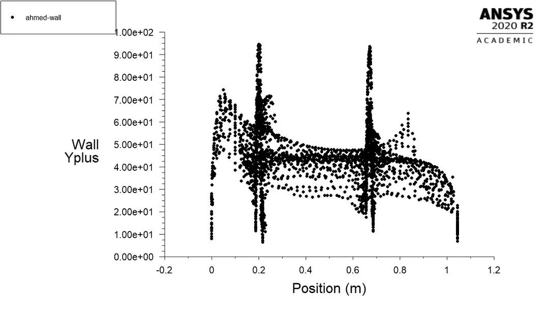
Since the flow is turbulent, the K-epsilon turbulence model is used. The reason for the use of the turbulent model is that the flow has a high Reynolds number and the y+ values are greater than 30.
Y+ plot for the Ahmed body.
Boundary conditions:
Type: inlet velocity and outlet pressure
Inlet : Velocity = 25m/s.
Outlet : Pressure = 0 Pa.
Side, top, and bottom walls of the domain = symmetry.
Ahmed body = No-slip wall.
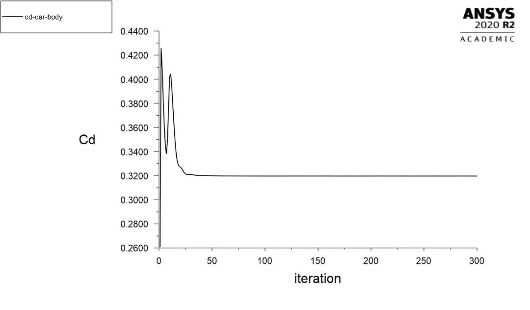
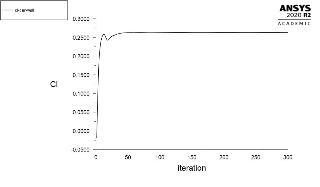
Plots are defined for drag coefficient and lift coefficient and also the velocity and pressure contours from the definition and contours menu respectively.
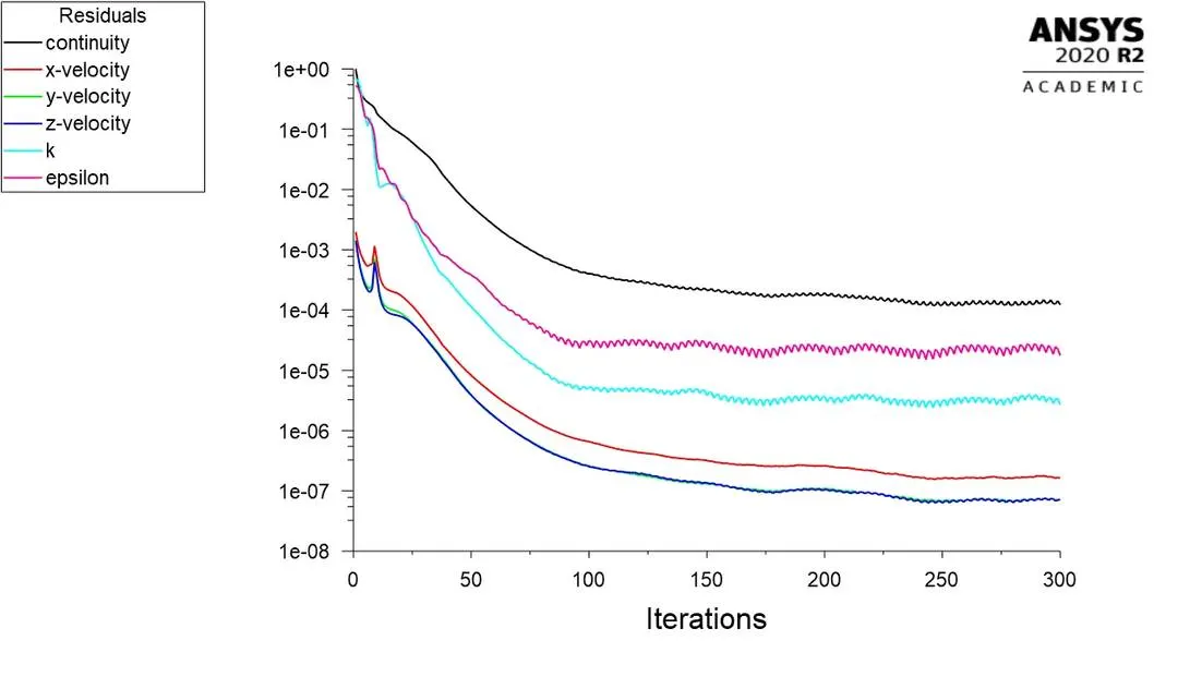
Simulation is run for 300 iterations.
Residual plot.
Drag Coefficient Plot
Lift coefficient Plot
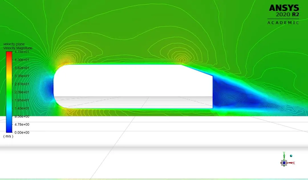
Velocity Contour
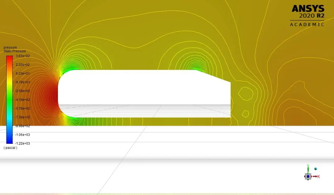
Pressure Contour
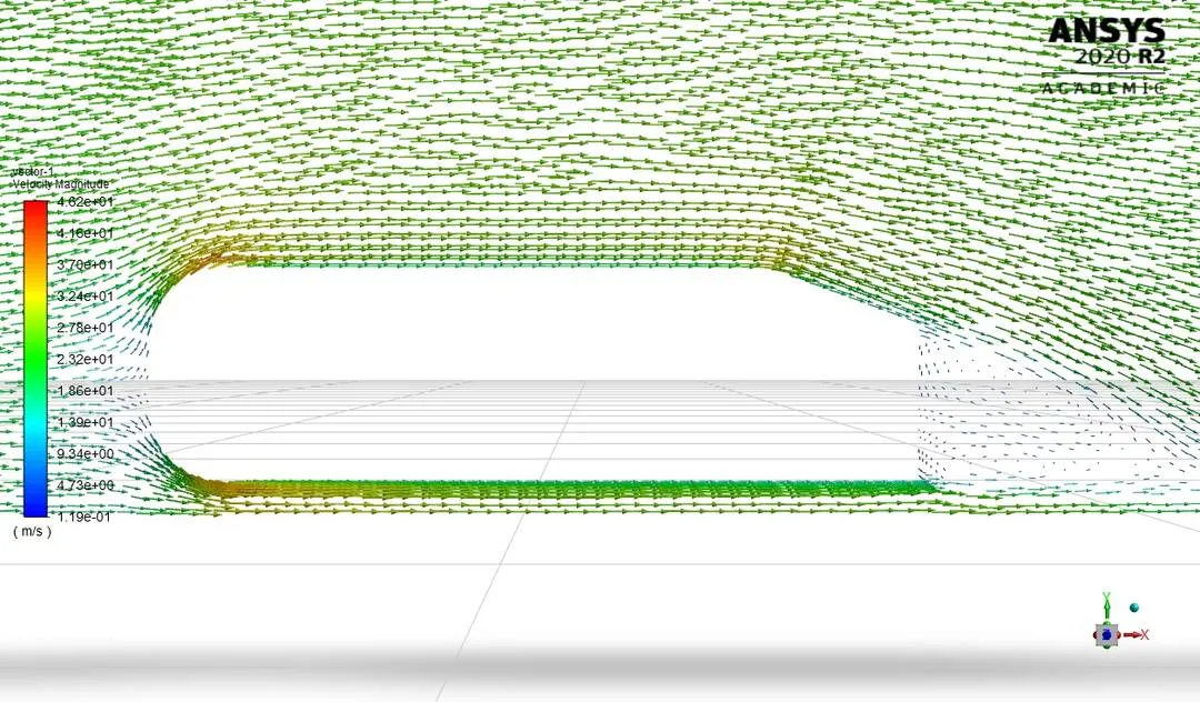
Vector plots
Velocity Pathlines 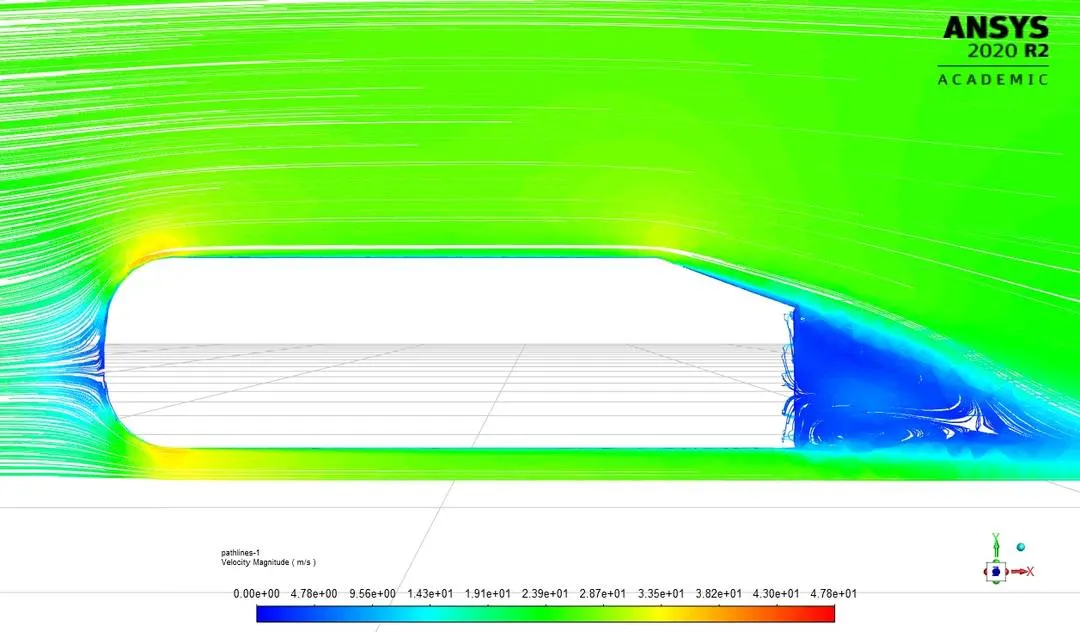
From the above plots, two eddies are formed at the wake regions for the given slant angle.
Inference from the above plots:
The velocity of the fluid decreases at the front end of the Ahmed body due to the impact of the fluid at the front area which increases the pressure. This causes the fluid to flow towards the low-pressure region that is towards the top of the Ahmed body where the velocity is high. The main principle behind which relates velocity and pressure is the Bernouilles principle which states that the higher the velocity lower the pressure and vice versa. Hence the fluid flows towards the top region where at a point of the radial curves it creates a high-pressure point which causes downforce on the body and then accelerates as it advances towards the rear region.
As the flow advances towards the rear part of the body, the flow detaches as there is a sudden change in the geometry and results in the formation of the wake.
The reason for the wake formation is that the slant edge created leads to the creation of a vacuum(low-pressure region) where air can't properly fill as a result negative pressure region is created near the wake region which results in the generation of a drag force.
The design which creates a large wake region is insignificant as the large wake regions lead to the formation of larger eddies which creates pressure disturbances in the flow. Hence the point of separation of flow should be at the end of the body as possible which creates a smaller wake region subsequently reducing the drag created due to the formation of the eddies.
Grid Independence Test.
Case 2:
Mesh Parameters:
The mesh cell size for the outer domain is 30mm
The mesh cell size for the inner domain is 100mm.
The inflation layer total thickness is 12.5mm.
The number of divisions at the circular edges = 36 divisions.
No. of Elements = 285704
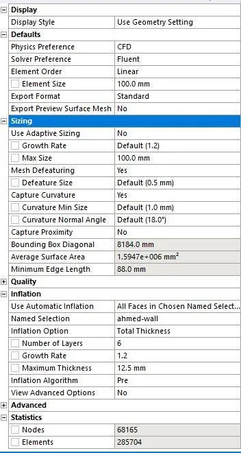
Inner domain mesh parameters
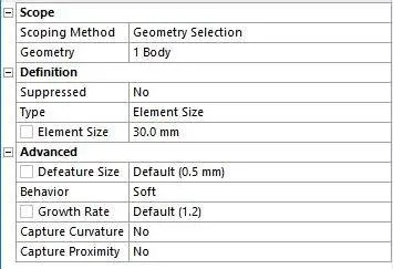
Mesh

Physis is the same as for the refined case.
Case 3:
Mesh parameters:
The mesh cell size for the out domain is 50mm
The mesh cell size for the inner domain is 100mm.
The inflation layer total thickness is 12.5mm.
The number of divisions at the circular edges = 36 divisions.
No. of Elements =
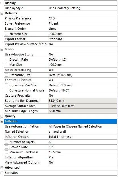
Mesh parameters for the inner domain
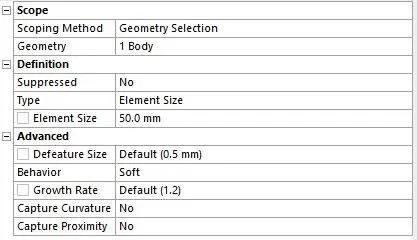

Table showing drag and lift coefficients for each grid independency test.
|
Mesh Size |
No. of Elements |
Cd |
Cl |
Error % |
|
Base Mesh size 50mm Inner body size = 26mm |
498521 |
0.319 |
0.262 | 3.33 |
|
Base Mesh size 50mm Inner body size = 30mm |
285858 | 0.314 | 0.241 | 4.84 |
|
Base Mesh size 100mm Inner body size = 50mm |
103850 | 0.349 | 0.224 | 5.75 |
Inference from the above table:
From the above table with the refinement of the mesh drag coefficient approaches closer to the analytical values that are because more cells are assigned at the boundary layer which results in more accurate results of drag coefficients.
Conclusion:
1. High pressure is formed at the frontal area of the Ahmed body due to loss of kinetic energy of the air.
2. Adverse pressure gradient is created near the wake regions because of the flow separation which is occurring because of the geometry of the model. As a result flow separation alters the pressure gradient which in turn affects the drag and lift coefficients.
3. In order to reduce the size of the wake region, detachment of the fluid should be farther away from the body which can be achieved by an increase in the slant angle.
4. With the decrease in mesh size the numerical results approach closer to experimental results.