Advanced Sheet Metal Design Using NX Cad Challenge_7_ Metal bracket-II
DESIGNING OF METAL BRACKET USING SHEET METAL IN NX CAD
OBJECTIVE:
- The main objective of this project is to use and learn the tools and operation while designing the Metal Bracket from the given 2D drawing.
- Learned the Drafting of Sheet, Advanced Flange feature and using of Gussets.
INTRODUCTION:
Sheet metal is used in various platforms in manufacturing industries. Sheet metal is metal made by the industries to make thin, flat piece. In NX CAD sheet metal application is used in Machineries, Automobile industries, Aerospace industries, etc. It is made up of Steel, Aluminium, Copper, Brass, Tin, Nickel, etc. It comes with a foil rolled along itself. Sheet metal enclosures is use to resist corrosion and provide electrical conductivity. The product is widely used for various industrial purposes. The brackets are made by the use of metal stampers. The metal brackets are used to maintain hole alignment and provide strength to the model in automobile industries. The brackets are also used to provide a rigidity to overhanging objects. In western countries this metal bracket is used to protect a house from the tornado. Here I have designed a simple metal bracket design.
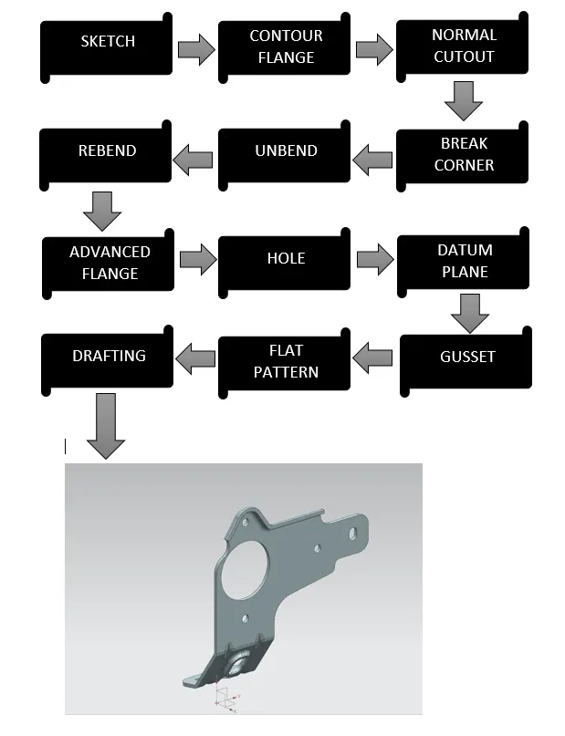
DESIGN METHODOLOGY:
DESCRIPTION:
- SKETCH: This is used as a primary feature for any type of modelling.
- COUNTOR FLANGE: By using this command we can add a flat flange to the model at a required angle.
- NORMAL CUTOUT: This command is used to remove the material from a model. The cut made by using this feature will be perpendicular to the face.
- BREAK CORNER: This command is used to create a smooth corners to the edges.
- UNBEND: This command is used to unbend the sheet metal to perform deferent operations which can be operated using unbend feature only.
- REBEND: After finishing all these operation the sheet metal parts need to rebend to its previous bend state. After rebending we can see that all the operation we have performed after unbend feature. They can now also been seen without any change in the parameters.
- ADVANCED FLANGE: This feature also adds a flange along the edges using bend angle.
- SIMPLE HOLE: This feature is used to create a throughout hole on the sheet metal in this exercise we have used this after unbending.
- DATUM PLANE: This feature is used to create a new plane for the design purpose.
- GUSSET: Gusset is a feature available in NX CAD. Normally gussets are given to any metal to transfer the stresses between connecting members. Which helps the joint to become more strengthen.
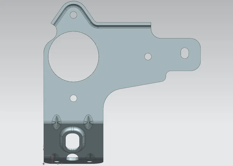
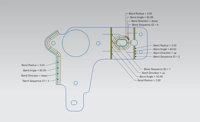
- FLAT PATTERN: This feature is used to create a 2D sketch on the sheet. The flattened model is necessary for the manufacturing process. This involved all the detailed dimensions required for manufacturing.
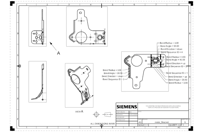
- DRAFTING: By using this feature we can easily create a Sheet that can be used for the manufacturing process.
PROCEDURE:
- To create a Metal Bracket we first need to select right co-ordinates. So to sketch we need to select YZ plane.
- After creating a required sketch using circles, lines and a rectangle.
- Again create a sketch on the XZ plane using lines.
- Now proceed toward the feature called as contour flange. Which has a thickness of 3mm and width about 158mm.
- Now use normal cut out feature by selecting the curves and target the body.
- Again do the same for another part of the sheet.
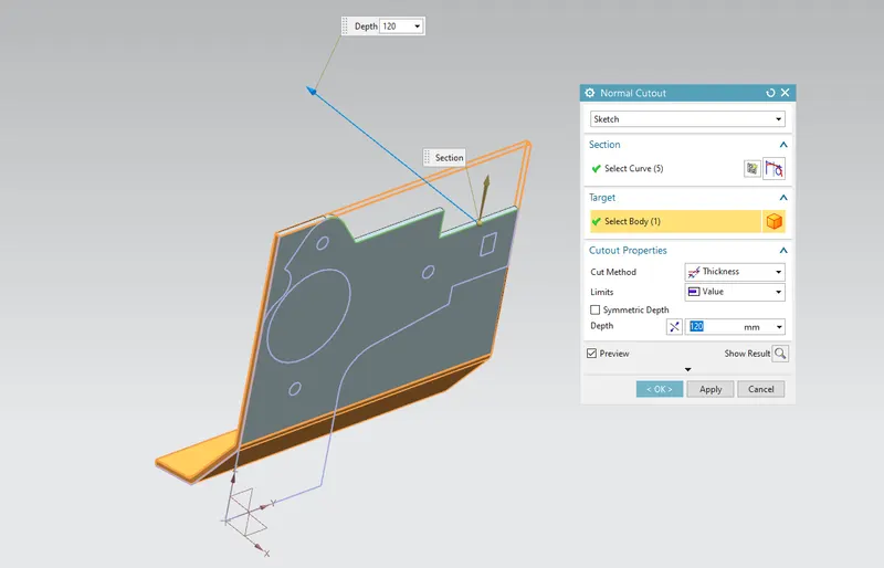
- Now use break corner option to provide better surface finish.
- Use normal cut out for another part of sheet to get required shape of the model.
- Now select the circles and a rectangle from the sketch and perform same operation to create a cut out on the model.
- Use break corner feature on the rectangular shape cut out for better surface finish.
- Now unbend the model.
- Draw a new sketch on the YZ plane using circle.
- Use normal cut out feature over it.
- Now rebend the model and use break corner feature.
- Now use the Advanced Flange feature on the top face which has the length of 5mm at 90 degree angle.
- Again unbend the model over stationary face.
- Now create two holes and a rectangle at required place.
- To create a hole use hole feature and provide required dimensions to the operation.
- Apply break corner feature on the rectangle which length and height is 20mm and 27mm respectively. Apply Normal cut out feature over it.
- Now use Advanced Flange feature on the particular edge with 4mm length at 90 degree angle select material outside for this.
- Now rebend the model so that we can apply gusset to the week joints to increase the strength at that point.
- To apply Gusset I have created two new datum planes at a distance of 45 mm and 13mm respectively.
- Now select the face where we need to apply the Gusset and select the required planes to get the result. The depth size of 5mm, width is 8mm, side angle is 45 and die radius of 2.5mm is required.
- Simply repeat the step. For the bottom side gusset I have used the option of specify plane and the selected at a distance option. I have provided a distance of 11mm and 47mm from the XZ plane.
- Now create a flat pattern of the metal bracket draft the sheet.
- At last save the file with the name of Metal Bracket.
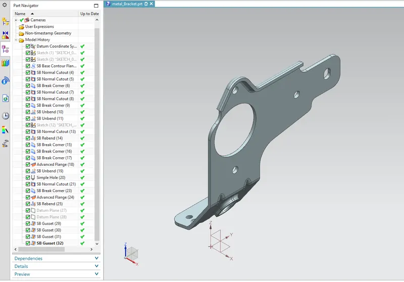
ISOMETRIC VIEW:
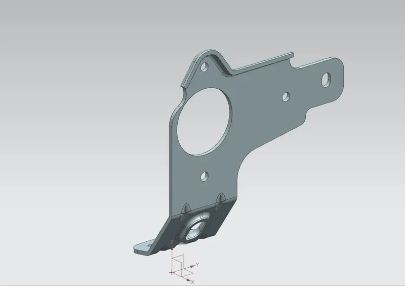
TRIMETRIC VIEW:
FRONT VIEW:
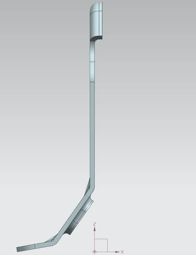
TOP VIEW:
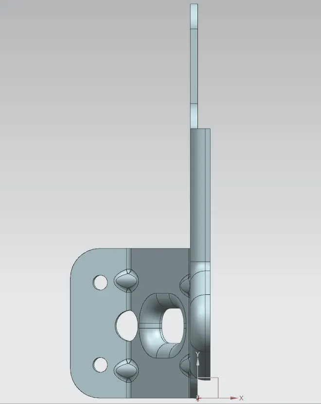
BOTTOM VIEW:
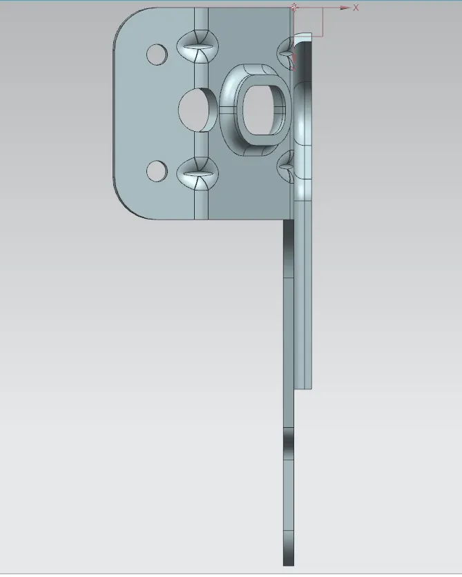
SIDE VIEW:
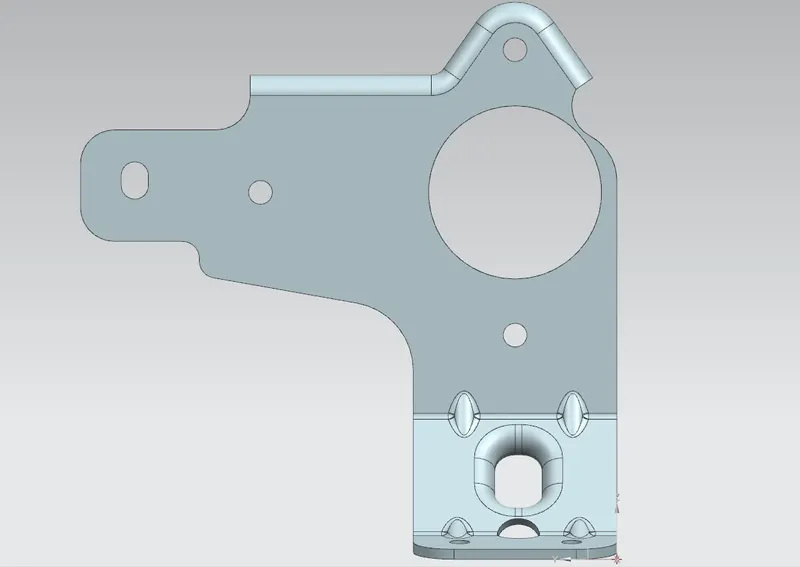
FLAT PATTERN:
DRAFTED SHEET:
CONCLUSION:
TO MAKE A SHEET METAL BRACKET ALL THE FEATURES AND TOOLS ARE APPLIED AS REQUIRED. THIS PROJECTS IS CREATED USING SIEMENS NX CAD
NAME: AVINASH RAJU LANJEWAR