Photo Realistic Rendering
DESIGN OF AMERICAN CHOPPER USING SOLIDWORKS
INTRODUCTION
In this report there is an explanation of designing of American chopper, complete part modelling, assembling and final rendering of assembly is explained.
OBJECTIVE
The main objective of this project is to learn and model different parts of American chopper using solid works. By modelling different parts individually and assembling them together, application of decals, selecting appropriate scene, lights and camera setting to get the final model of American chopper.
Creating a photo realistic view by rendering the model using solid works photo view 360 and solid works visualize.
PART MODELLING
The assembling of different parts together to get the final model is called as part modelling.
COMPONENTS
The American Chopper has this different type of component which is assembled inside solid work.
- Transmission Belt
- Kick stand
- Chain
- Front fender
- Front wheel
- Rear fender
- Real wheel
- Front fork
- Pedal
- Oil tank
- Chassis
- Engine
- Gas tank
- Assembly
DESCRIPTION OF THE PARTS AND FEATURES USED IN AMERICAN CHOPPER MODEL
- TRANSMISSION BELT
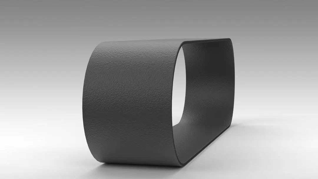
Transmission belt is made of flexible material used to transmit power from engine to gearbox. This is used to rotate shafts mechanically with parallel mechanisms. To make a profile of a transmission belt in American chopper model, sketch it on the front plane with an offset of 3.5mm, after the completion of the sketch we need to extrude. Remaining design is completed by adding fillet on edges of belt. In appearance mode apply matte rubber by selection each and every face.
FEATURES USED
- Boss extrude: - Extrude is a type of feature which is used to convert 2D sketches into 3D models.
- Fillet: - Fillets are made to give smooth rounded internal or external faces on model or in the sketch with round option.
- KICKSTAND
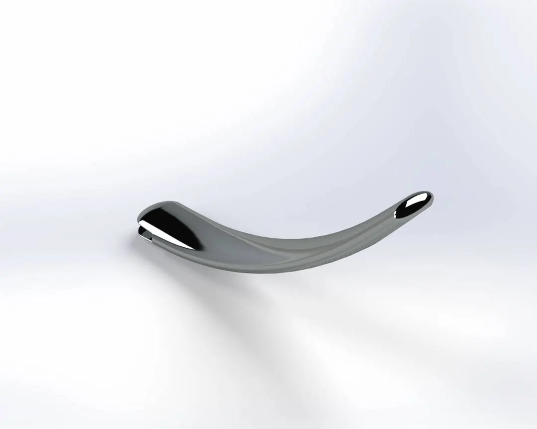
Kickstand is used to support the American chopper to keep. It is also known as a side stand. The material used here is steel.
FEATURES USED
Lofted boss/base, Dome, Extrude Cut, Extruded Boss/Base and Fillet
To create a side stand two ellipses are created on the right plane, to join both the ellipses the spline command is used and after that when the path is created on the front plane we need to use a pierce relation between the path and centre of the ellipses. Using loft the sketch is created into a 3D model. The sharp edges of the kickstand are applied with a fillet option. Elliptical dome features are used to give a proper look to the kickstand. A slot with an extruded boss is created at the top end of the stand using which it is connected to the chassis. To get a proper merge to the ground, a split feature is used to split one end of the kickstand which will rest on the ground. At last chrome plate appearance is applied to the kickstand.
- CHAIN
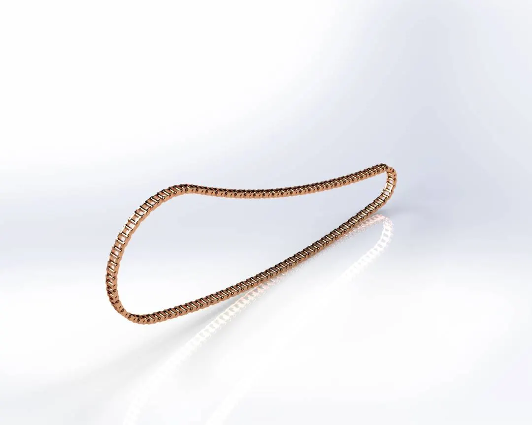
Chain is used as a power transmission tool which transmits power from engine to the Rear Wheel. Generally, the material used to make chain is low carbon steel. The rear wheel has an attached tool on which the chain passes over which is called a sprocket.
FEATURES USED
Extruded Boss/Base, Linear pattern, Circular pattern, Fillet, Mirror and Combine.
To create chain following features are required. To make 2D sketches we need a three-point arc and tangent relation between arcs. We need to create two throwaway sketches which are used to create inside and outside links of the chain. Then the plates of chain links are extruded using throwaway sketches and the connecting pins are created using the same sketch. We need to create only one side of the chain link after making the front side link we must use a mirror for the other side. The created chain plate and pin are added together on the main sketch using linear pattern and circular pattern features. After that it has been mirrored along the front plain. All the components of the chain are combined as a single part using a combined feature. In solid bodies it must be arranged in proper pins and plates as shown. At last chrome steel appearance is applied to the chain.
- FRONT FENDER
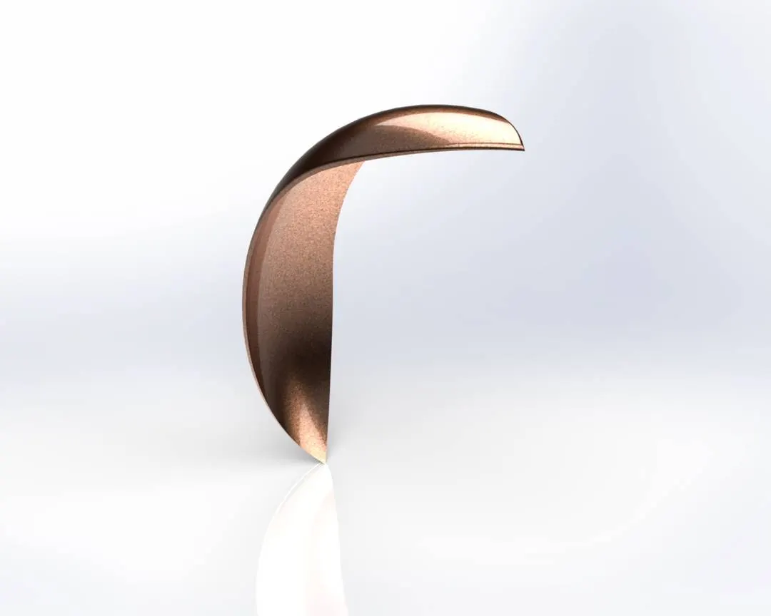
Fender is the american english term for the part of an automobile, motorcycle or other vehicle body that frames a wheel. In this model the front fender is mounted on the front wheel as a covering plate of the front wheel to protect the rider and chopper from dirt particles and foreign particles.
FEATURES USED
Revolve Boss/Base, split and shell
A sketch is created in the front plane using a three point arc and offset which gives the thickness of the fender. We need to create an axis at the origin. Using revolve boss it is created. Two different sketches are created on the top plane and the right plane to get front fenders required shape. To provide a smooth surface on edges fillet is given. At last required appearance is provided.
- FRONT WHEEL
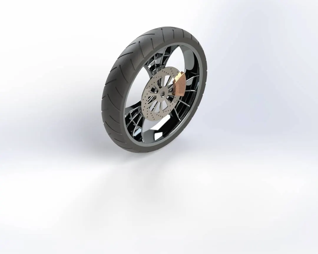
Front wheel is a rolling part situated on the front of the chopper. This wheel helps to guide the vehicle according to the movement of the front fork as required by the rider. A wheel is a block made up of steel/alloy material. On the top of the wheel tyre is attached. The tyre is made up of Rubber and it has thin strips over it to provide proper grip to the chopper.
FEATURES USED
Revolve Boss/Base, Extrude Boss/Base, Extrude cut, Revolve Cut, Circular Pattern, Mirror, Combine, Chamfer and fillet.
A sketch is created on the front plane which includes a rim portion, that requires the revolve feature along the imaginary axis at the origin. A spider web design of the rim is created and is extruded using the midplane extrude feature. After the completion of the rim we need to use a circular pattern to get the required numbers of rim. At the next step the spider web spoke and the rim both are combined using a combined feature to get a single solid body. To get a required design we need to add additional sketches of Rotor, Caliper, Tyre.
ROTOR
For rotor, sketch on the front plane and extrude it on the required dimensions by creating required holes at proper distance and with a proper dimension using circular pattern.
CALIPER
To design caliper create a profile using lines and circles, and remove the unwanted sketch and extrude caliper using midplane features. Provide necessary fillets and chamfers to complete the caliper design.
TYRE
To design tyre create a sketch using convert entities using the Rim design. Tyre is extruded. Later profiles are created on the surface of the tyre to give grips of the tyre. To give that gripes cut extrude feature is used. At last rubber, chrome and siana appearance is applied as required.
- REAR FENDER
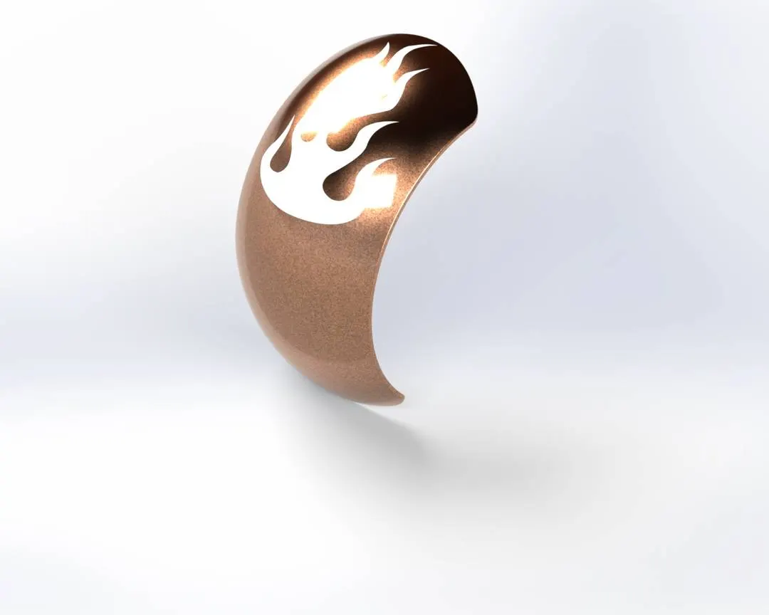
Rear fender is applied to the vehicle for the same purpose as the front fender. The rear fender is mounted on the chassis of the rear part above the rear wheel to protect the body from mud. It is the semi circular cover on the rear wheel.
FEATURES USED
Revolve boss/bass, offset entities, trim entities, fillet and shell.
To create the sketch a three point arc and offset entities is required. Offset entities are required to get the thickness of the fender. Axis is created on the origin. Using a revolve boss the required rear fender is created. Fillets are created on the sharp edges of the fender to get a smooth curve. At last desired appearance is applied to the fender.
- REAR WHEEL
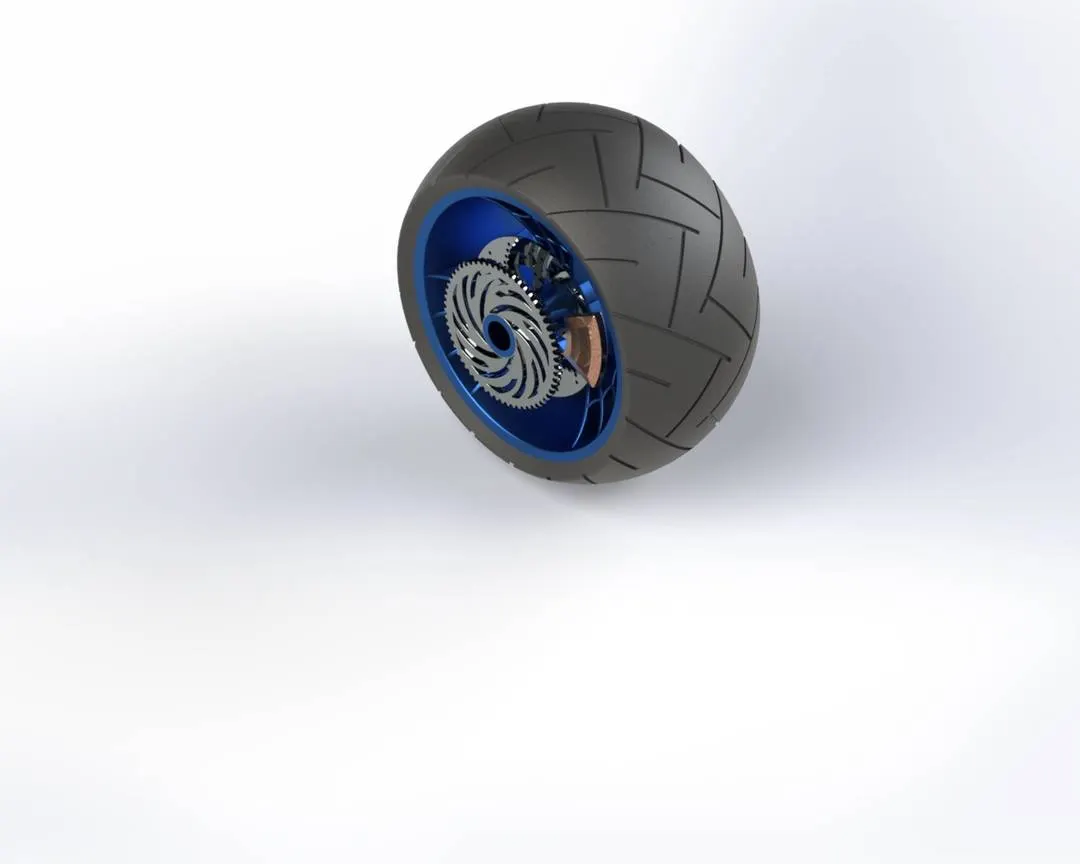
A circular object is placed on the rear side of the vehicle to provide motion to a vehicle and it receives power from the engine through chain drive. This circular object revolves along the axle. The disc and the sprocket are attached to the rear wheel, disc and sprocket have their individual function. Between the engine and the rear wheel chain is connected. Chain is a positive drive. Compared to the belt, the chain is more efficient.
FEATURES USED
Revolve Boss/Bass, Extruded Boss/Base, Extruded Cut, Revolve Cut, Circular Pattern, Mirror, Combine, Chamfer and Fillet.
First a sketch is prepared on the front plane and a revolve extrude feature is used along an imaginary axis at the origin to get the desired shape. A spider web design is created on the front plane and is extruded using a mid plane feature. After that a circular pattern feature is used to get the required rim.
ROTOR
Sketch on the front plane and extrude it to the required dimension. Create the necessary holes using circular pattern features.
CALIPER
By creating a required profile with given dimension and removing unwanted sketches this profile is made. Fillets and chamfers are given to the profile to get a smooth curve.
TYRE
A sketch is created by converting entities of the rim. Later a revolve bass feature is used to get the required structure of the tyre. Profile is also created on the tyre to get a grip like structure.
SPROCKET
For sprocket sketch a circle and it is extruded to the required thickness. To create a tooth profile apply chamfer to the outer edge. Use an extrude cut option up to next. And apply fillets to the tooth edges and create the sprocket using circular pattern features. To get appropriate numbers of teeth on sprocket use given dimensions.
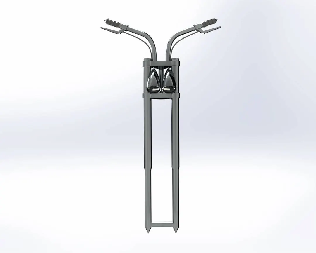
- FRONT FORK
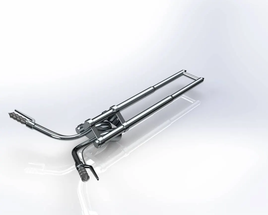
Front fork is used to guide the vehicle. The front wheel is fixed to the front fork. Front fork also holds other control units operated by the rider. It consists of two columns along with a shock absorber which is held together by a triple clamp.
FEATURES USED
Extruded boss/base, Revolved boss/base, Extruded cut, Revolved cut, Project curves, Swept boss/base, Dome, Combine, Mirror, Chamfer and fillet.
The sketch is created in the front plane with appropriate dimensions. Revolve extrude feature is used to give required shape. Then create half of the triple clamp using appropriate dimensions. Then create a sketch for headlight using revolve extrude complete the sketch. Now on the top plane draw the next sketch using a spline and sweep pattern to create a handle to control the vehicle. After that use a mirror feature to complete the fork and combine both the bodies. At last chrome appearance is given to the front fork.
- PEDAL
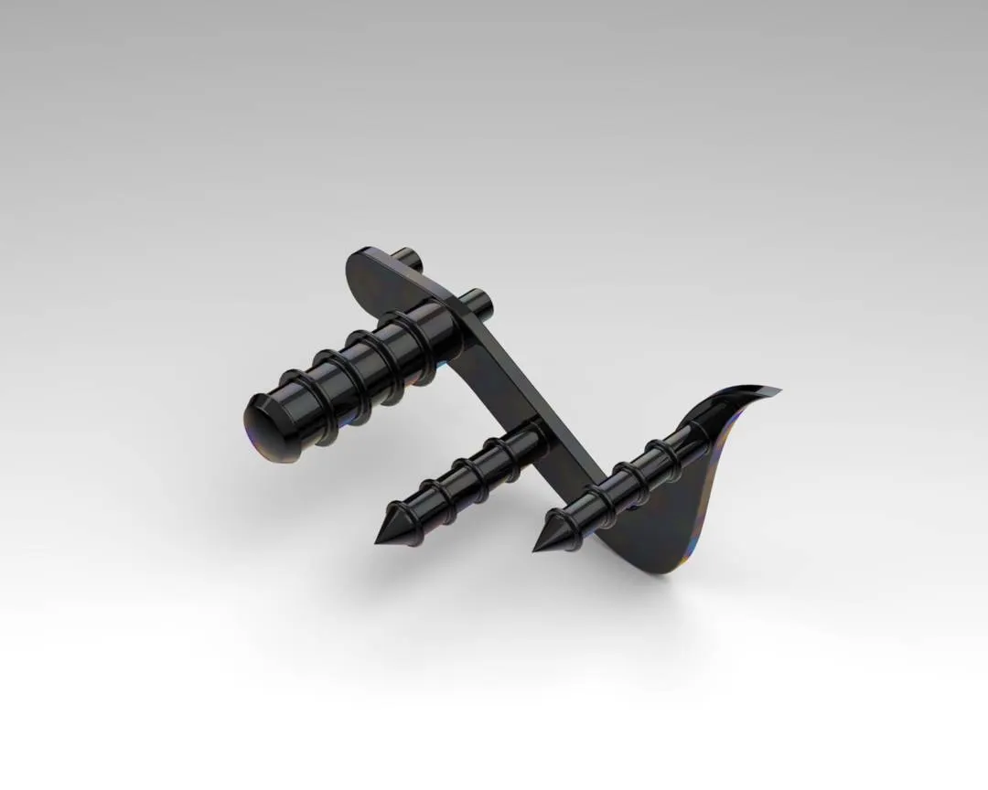
This part is fixed on the chassis of a motorcycle where the foot of the rider rests. The gear and brake is mounted near to the pedal so that the rider can easily shift the gear and can apply the brake and due to this it is easily available for the rider.
FEATURES USED
Extruded boss/base, Revolve boss/base, Dome, Linear pattern, Chamfer and Fillet.
To create a pedal first sketch on the front plane using a spline and few circles with appropriate dimensions. The circle profiles are later extruded to the cylinder structure. Later that structure is added with fillets and chamfer. A ring type structure is provided to pedal by using the converting entities option and then a linear pattern feature is used. At last chrome appearance is provided to the pedal.
- OIL TANK
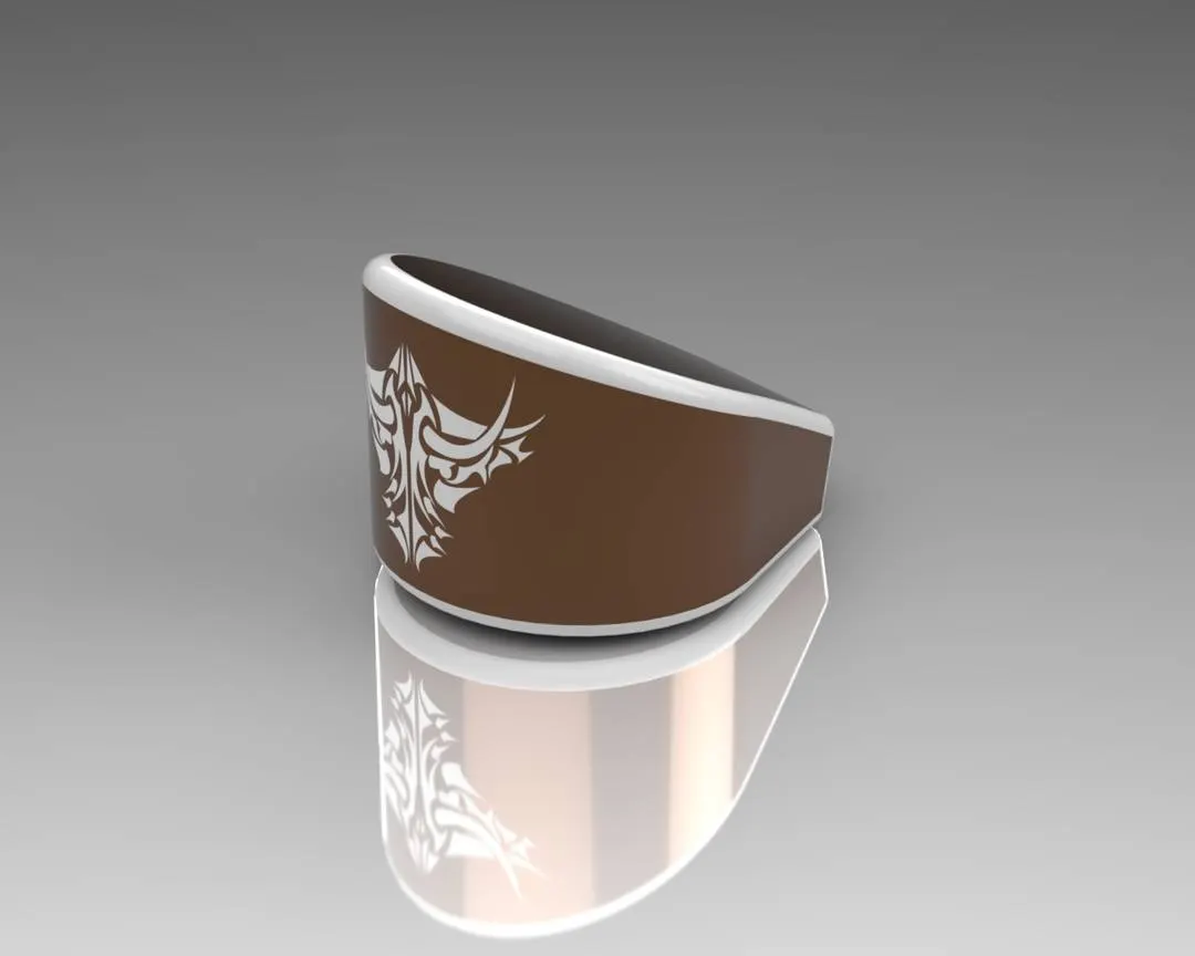
As named this unit is used as an oil storage that is required to run the engine properly and smoothly. Oil tank is hollow with the thickness of 3 mm in this motorcycle.
FEATURES USED
Extruded boss/base, Shell, Fillet and Combine.
To create the sketch use a 3 point arc and line then make the tangent relations. Then extrude the profile to obtain a structure. On the front plane create another sketch and extrude it using midplane extrude. After that, split the bodies and remove the unwanted part to obtain the oil tank. Use shell features to make the oil tank hollow and apply fillets as required. At last apply required appearance to the Oil tank.
- CHASSIS
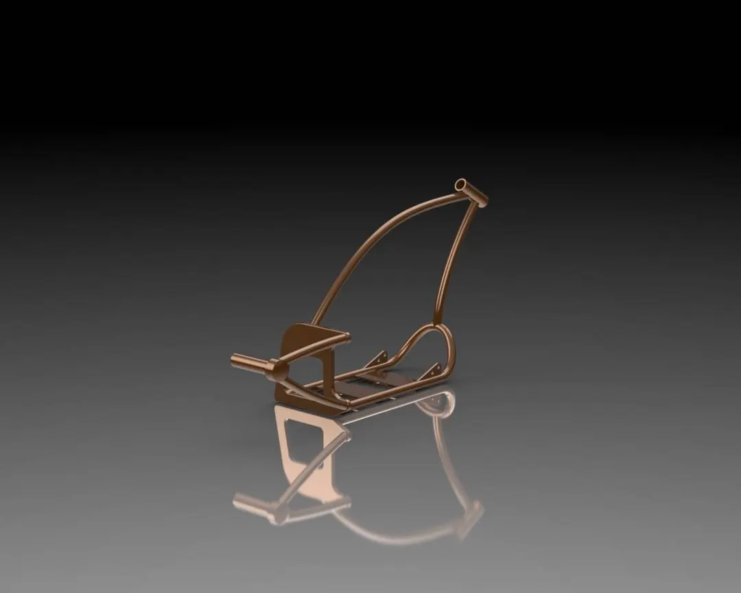
The chassis is the skeleton of the vehicle. All the main components of the vehicle are attached to the chassis like Suspension, Fork, Engine, Wheels, Fuel Tank, Oil tank, seats, etc. Chassis is made as strong as to bear each and every type of load act on the motorcycle.
FEATURES USED
Extruded boss/base, Revolve boss/bass, Linear pattern, Revolve cut, Extruded cut, Swept boss/base, Projected curves, Dome, Combine, Chamfer and Fillets.
To make chassis a blueprint of the vehicle is important. By adjusting the location, transparency and the sketch of the chassis, the modeling is started. The chassis is made up of 4mm thick tube and joined using splines and created projected curves. Different planes are needed to make this design complete as required. Then all the tubes are connected to a plate and the chassis is extended till the rear wheel. At last required appearance is given to the chassis.
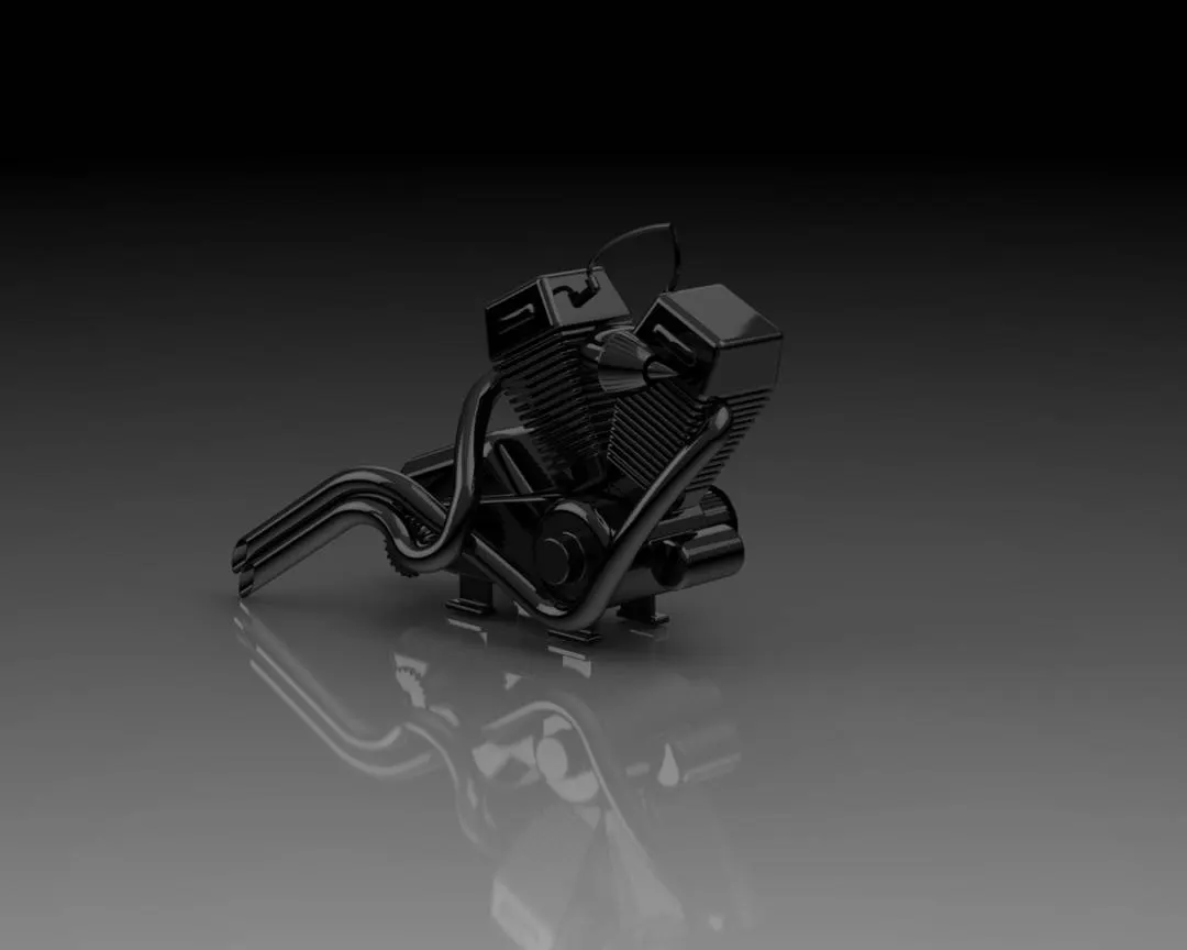
- ENGINE
Engine is the main component of the vehicle where the power is generated. In engine chemical energy is converted into heat energy and then this heat energy is converted into mechanical work. In this case mechanical work is rotational. This rotational work is transferred to the rear wheel with the help of chain sprocket which provides motion to the vehicle as required by the rider.
FEATURES USED
Extruded boss/base, Extruded cut, Revolve boss/base, Revolved cut, Projected curve, Circular pattern, Swept boss/base, Combine, Fillets, Mirror, Chamfer, Dome.
To design Engine again blueprint is required, the sketch is drawn on the front plane. The base of the engine is created using 3 point arc and lines using tangency properties and it is extruded. Then using the same sketch extrude the circles. After the compilation of the engine base, sketch on the front plane the upper part of the engine, then use mirror feature to get a V-shape twin engine. To hold the transmission belt a pulley structure is made with revolve extrude. The starter is deployed on the front plane having a shape of cylinder. The fins are made with the help of cut extrude and linear pattern. Using the curves and projected curve, create the profile for exhaust pipes by using swept boss feature. Then the spark plug is created using the same method with different dimensions. Fillets are applied to the required parts to get smooth curves. At last metallic appearance is provided to the engine.
- GAS TANK
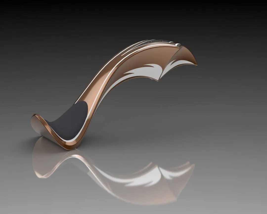
The gas tank or fuel tank is used to store the fuel. From this storage tank fuel is supplied and with the help of carburetor air fuel mixture is supplied to the engine as required.
FEATURES USED
Swept surface, Loft surface, Boundary surface, Projected curves, Knit surface, Sweep cut, Mirror, Combine, Shell, Fillets.
In the design of Gas Tank there is a use of different surface features. In the front plane using splines, construction lines and projected curve half of the tank is created. Now mirror the haft tank and use a surface knit option. Now by using a split line feature seat is created. Then fillet is used to give a smooth surface to the Gas Tank. At last appropriate appearance of material is provided to the seat and Gas Tank separately.
- ASSEMBLY OF THE CHOPPER
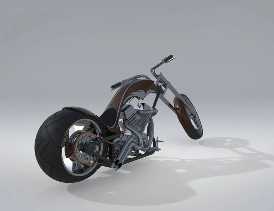
Firstly all the designed components are opened into the assembly section of the solidworks. Now Chassis is first inserted by using the insert part option. Now different types of mates are used to give proper position to the model as required. Mates such as concentric, coincident, parallel, tangent etc. are applied to the models. After that each part is inserted into the assembly by insert option and provided them with appropriate mate conditions so that the assembly should be fixed. After assembly the Decals are applied to required parts of the chopper.
- RENDERING :-
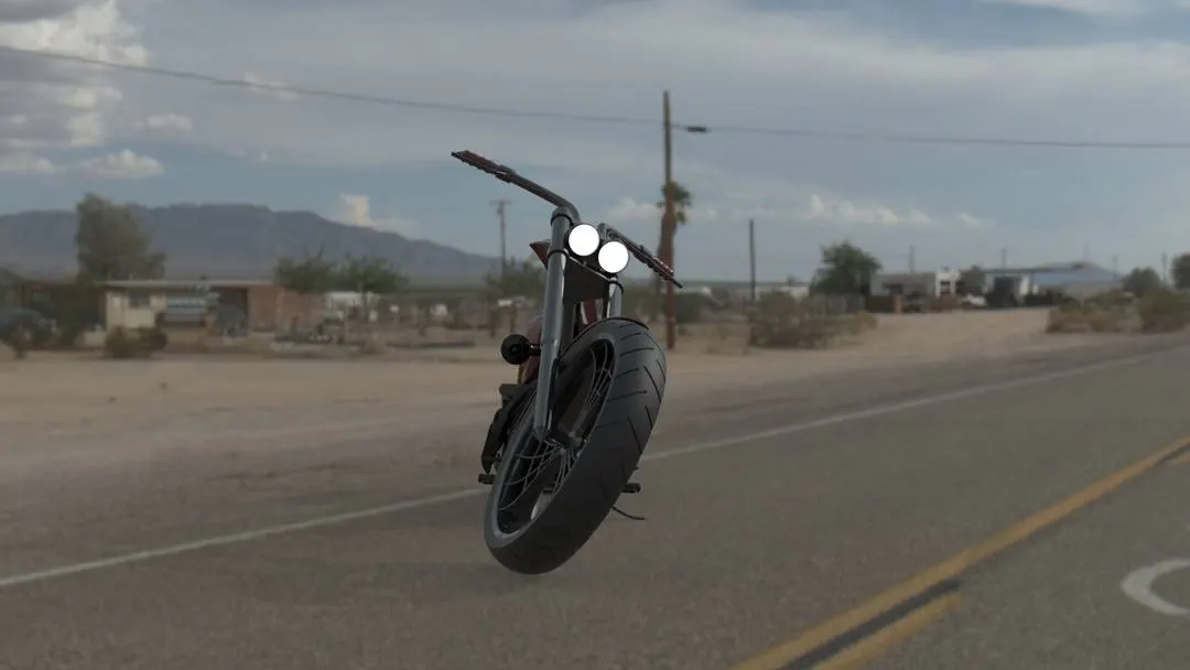
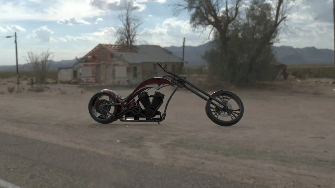
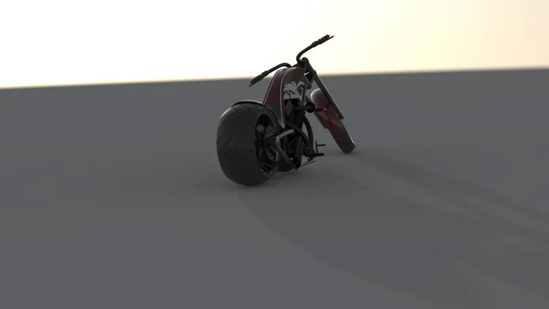
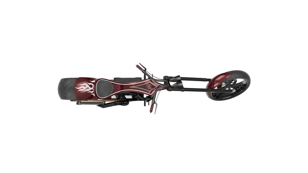
Rendering is the process of generating an image from a model, by means of a software program. It creates a realistic image of the model.
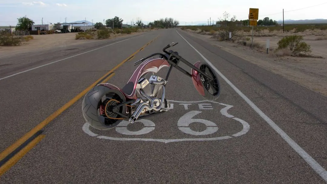
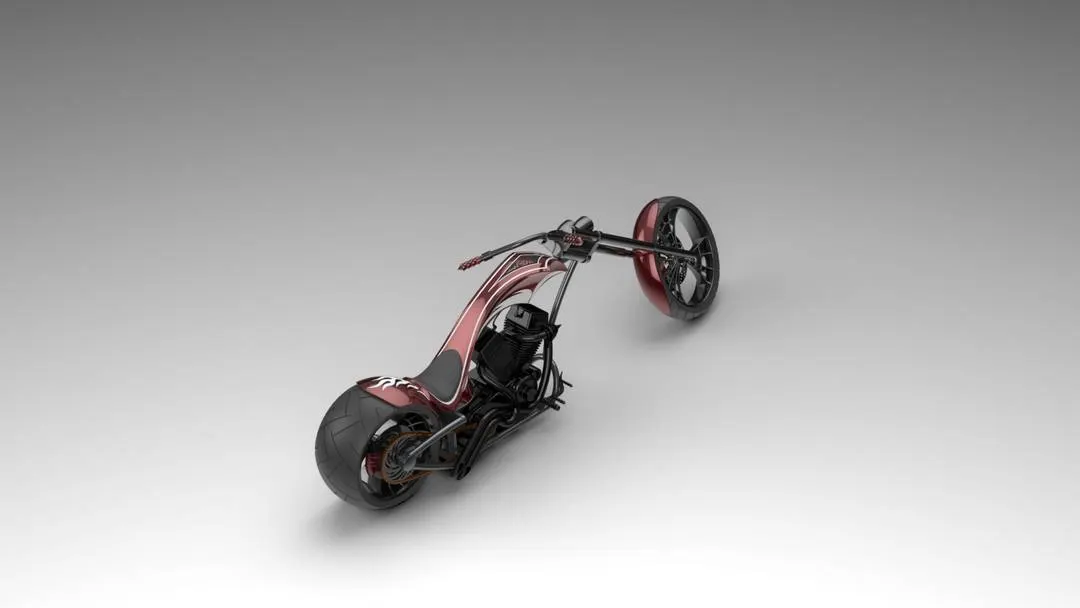
After the application of the decals is completed the assembly is taken into Solid Works Visualize or into the Photo-View 360 for rendering. Later this assembly is gone through different aspects such as adding scenes, camera, file libraries and applying new appearances as required. The main function here is to apply backplates inside the scenes option. Photorealistic model is obtained using rendering options. By applying this process we can easily obtain a rendered American Chopper with realistic images.
SOME RENDERED IMAGES OF AMERICAN CHOPPER ARE GIVEN BELOW
CONCLUSION :-
- All the parts of the American Chopper are modelled.
- The assembling of American Chopper is completed inside the assembly environment.
- The image was rendered by using Photo view 360 and Solidworks Visualize.
I specially thank to my mentor Mr. Soundar Rajan for guiding me and helping me with the difficulties I face during completion of this project.
NAME:- AVINASH RAJU LANJEWAR
THANK YOU