Assembly of Yacht
NAME:- AVINASH RAJU LANJEWAR
DESIGN AND MODELLING OF SUNSEEKER PREDATOR YACHT USING SOLIDWORKS
INTRODUCTION
In this report there is an explanation of designing of Sunseeker Predator Yacht, complete part modelling, assembling and final rendering of assembly is explained.
Sunseeker International is a British luxury performance motor yacht brand. Originally named Poole Power Boats, the company was founded by brothers Robert and John Braithwaite in 1969. The company changed its name to Sunseeker International in 1985 and has since become a global icon
OBJECTIVE
The main objective of this project is to sharpen the learning and improve designing. By modelling different parts individually and assembling them together, application of decals, selecting appropriate scenes and to understand the Surface Modelling methodology in 3D modelling using Solidworks.
Creating a photo realistic view by rendering the model using solid works photo view 360 and solid works visualize.
DESIGN METHODOLOGY
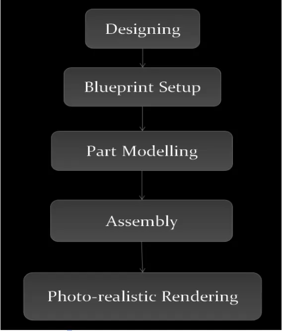
PART MODELLING
The assembling of different parts together to get the final model is called as part modelling.
COMPONENTS
The Sunseeker Yacht has this different type of component which is assembled inside solidworks and Rendered using PV360 and Solidworks visualize
- Propeller
- Radar
- BluePrint Setup
- Hull
- Garage Door
- Front Seat
- Middle Seat
- Rear Seat
- Superstructure
- Radar Mast
- Final Assembly
DESCRIPTION OF THE PARTS AND FEATURES USED IN SUNSEEKER PREDATOR YACHT MODEL
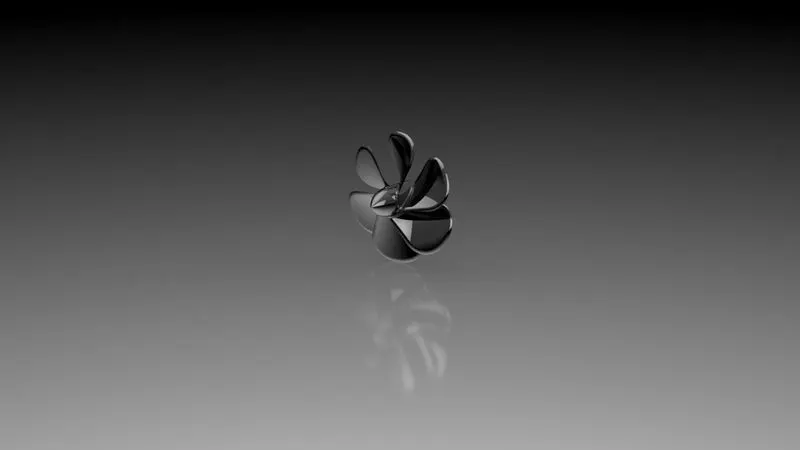
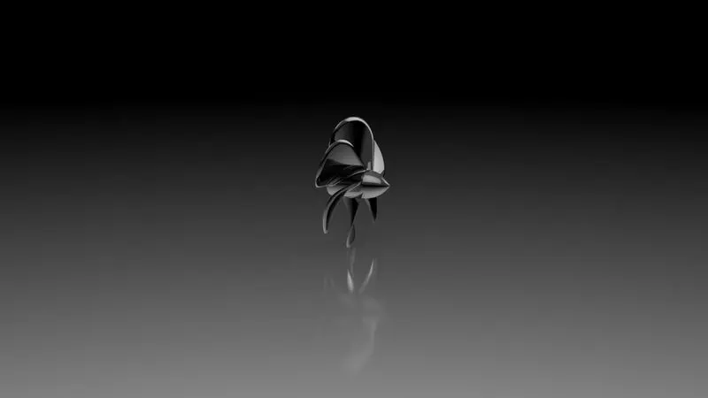
- PROPELLER
Boat propellers include blades that turn on a shaft, which is powered by the motor. Propellers can have 3, 4, or 5 blades. Typically, the more blades on the propeller, the more propulsion can be achieved. While the motor provides the power, the propeller is where all the action takes place. Propeller blades displace water, to create the forces that move a boat forward.
Bronze alloys, in particular, are the preferred metal for casting large ship propellers.
FEATURES USED
Revolve Boss/Base, Loft Surface, Cut Extrude, Circular pattern And Fillets
- Loft Surface:- This tool is used to create Critical curves. By selecting two or more sketches and specifying start and end constraints. Add guide curves to control the path shape.
- Revolve Boss/Base :- Revolve is used to create a 3D solid feature using 2D sketch.
- Cut Extrude :- This is used to create a cut on a solid body and remove a material according to the given dimension.
- Circular Pattern :- To pattern the face, features in a circular direction
- Fillets :- Fillets are used to provide smooth faces along sharp edges.
To create a propeller of a ship a sketch is made on Right plane. After exiting the sketch a Revolve extrude feature is used to get a solid body on which Blades are mounted. To create a blade two sketches has to be made to use a Lofted Surface feature to get a complex surface for blades. Now to get a smooth curve for blades fillet is used. Now use a circular pattern feature to place six blades on a single solid body, blades are placed in an equal distance on the circular body. At last required appearance is applied to the Propeller.
- RADAR
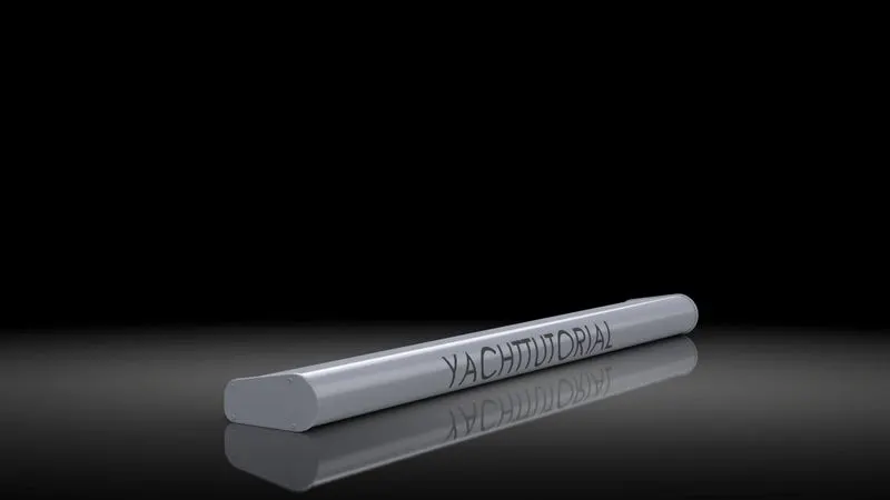
Radar (Radio Detection And Ranging) is a detection system that uses radio waves to determine the range, angle, or velocity of objects. It can be used to detect aircraft, ships, spacecraft, guided missiles, motor vehicles, weather formations, and terrain.
FEATURES USED
Extruded Boss/Base, Cut Extrude, Sketch Pattern, Mirror, Split-line and Fillets.
- Extruded Boss/Base :- This feature is used to create a 2D sketch contours into 3D solid body in one or two directions. It is opposite to the Extruded cut feature.
- Sketch Pattern :- It is used to create an instance pattern of a seed feature to as many required locations. The sketch driven pattern can only be used for dots, holes etc.
- Mirror Feature :- The Mirror Feature is used to create a Mirror image of the body, Face, Features which is required.
- Split-Line :- This feature is used to project the sketch on the surface our model
For the construction of Radar, Sketch is made on the Right Plane and Extruded to the given dimension. Using Offset entities another sketch is made and again uses the extrude boss feature to get the corner of Radar. Cut Extrude is used to get screws on the end of the cornered surface of Radar. Sketch pattern feature is used to lock the position of other 3 screws. Mirror feature is used to get the exact Radar. White colour is preferred as appearance for the radar and fillets are added to give smooth curves.
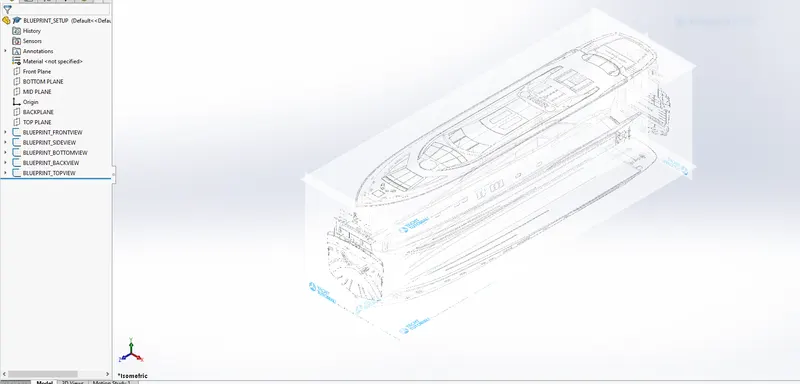
- BLUEPRINT SETUP
The Blueprints setup is used as a reference to allocate the position of the yacht. The height, length and width of the Blueprint is the same as that of the yacht model. There are 5 Blueprints used in the design of the yacht. The first hull part is made up by using this Blueprint and after that all the other parts are designed.
- Rear Blueprint
- Bottom Blueprint
- Front Blueprint
- Side Blueprint
- Top Blueprint
All the Blueprints are set up as the given dimensions.
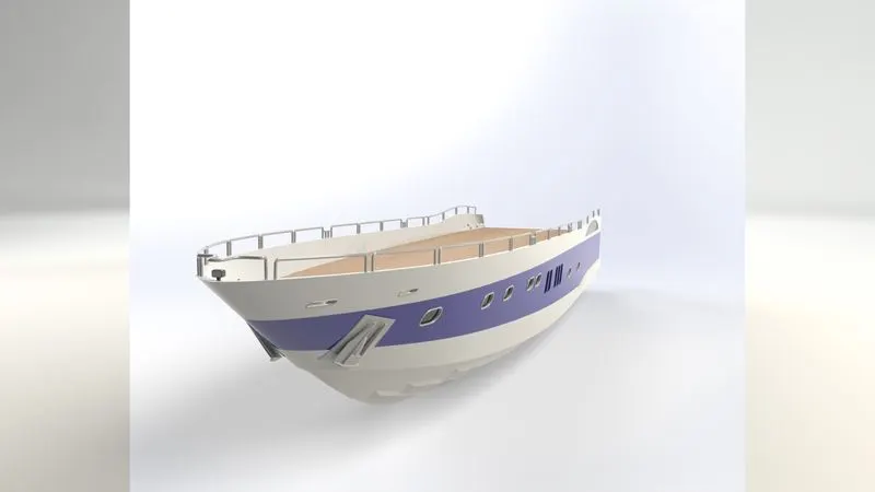
- HULL
The 'Hull' is the portion of your boat that rides both in and on top of the water. The boat hull does not include any masts, sails, rigging, machinery or equipment.
The hull of a ship is the most notable structural entity of the ship. To define the hull, it can be said that it is the watertight enclosure of the ship, which protects the cargo, machinery, and accommodation spaces of the ship from the weather, flooding, and structural damage.
FEATURES USED
Projected curve, Surface loft, Surface Trim, Surface Extrude, Surface Knit, Surface fill, Shell Operation, Boss Extrude, Cut Extrude, Sweep Feature, Revolve Extrude, Dome Feature, Helix Spiral, Linear Pattern, Extrude Boss by using Thin Feature,
- Project Curve :- This feature is used to create a 3D curve by projecting two curves drawn on different planes.
- Surface Loft :- This feature is used to create a surface between edges by creating a smooth tangency between the Selected Curves.
- Surface Trim :- This feature is used to consume extra or unwanted bodies.
- Surface Extrude :- This feature is used to convert 2D sketches into 3D surfaces.
- Surface Knit :- This feature is used to Knit multiple Surface to form a single surface.
- Surface Fill :- This feature also creates a surface between the edges but we use this only when there is a small patch to fill.
- Shell Operation :- This feature is used to remove a material from a solid body to create a thin-walled feature on the remaining Face.
- Sweep Feature :- This feature is used to generate a curvy solid body. To make this we need to select a sketch and a guide path.
- Dome :- A dome is a curved formation or structure. It is shaped like half of a sphere. It is used to provide a smooth surface on the faces.
- Helix spiral :- This is used to make a spring like structure.
- Linear Pattern :- In this a part is linearly created easily from one created body.
- 3D Sketch :- It is used to draw lines, circles, splines etc. Within a 2D sketch to connect two or more bodies in X, Y and Z direction.
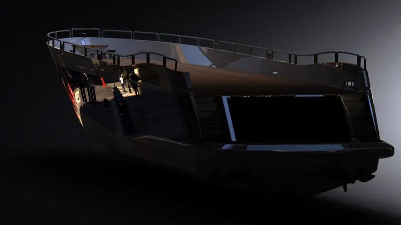
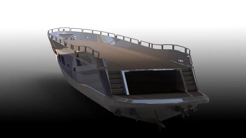
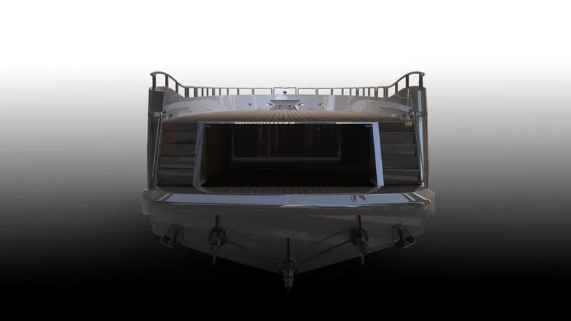
To design a Hull first we need to open the Blueprint Setup and save it as a Hull. Create two planes Back and top planes using a reference as front and bottom plane. Now start sketching on Top plane and side plane alternately to make cuve one and curve two. Create a surface with the help of surface loft feature. Make a solid body and then use shell operation on the face attached with mid plane. Create cut extrude to provide a boundary to the yacht. Now the porth holes mounted on the hull are to be created using blueprints. Appropriate slot has to be made to create the porth hole on the hull outer boundary.By using a copy feature, copy a slot to required position and extrude cut it. Now create a 2D sketch on a new plane and create 3D sketch using convert entities of porth holes. Now create a Solid sweep boss feature and repeat the steps for creating another porth holes. Create a new sketch on the top plane for the lower deck. Create a new sketch on the top plane for stairs and extrude cut it up to face. Now create a new sketch on the right face and draw a sketch using lines like stairs and extrude it up to next. A new plane is created with reference to the bottom plane at a distance of 3000mm upward from the bottom plane. Draw 3 splines offset it and draw a line to close the sketch. Use an extrude boss base feature. Now create a sketch on the top plane with two circles and connect them with lines and trim the unnecessary lines, extrude it. Now on a new plane make a sketch with horizontal lines and vertical lines to get desired shape, use revolve extrude. Create a sketch by drawing lines and circles, extrude it. To remove some portion from previous extrude, create a sketch and do cut extrude. Now use the helix spiral feature to create a rope. Now the side railing portion has to be made. In this portion we need to do a projected curve feature. Plane and mid plane as a reference. Just need to offset the inner edge of a hull and draw some vertical and horizontal lines to form a chain. Add fillets to the corner points. Create a new plane and draw a circle on it and add a pierce relation to the railing curve, sweep it to get a railing. Draw a sketch on the Back Plane using a few lines and extrude it, to develop caliper surface. Select the surface of the Caliper, draw a sketch as per blueprint & revolve it. Create a new sketch on the mid plane using some horizontal and vertical lines and revolve it to draw the propeller shaft. Pattern it with given reference. Use a 3D sketch to design connecting rods and to make this line use propeller shaft holes as a reference. Draw a sketch on Midplane at the front portion of Hull and extrude it and mirror it across the face to get an anchor for the yacht. Now use an offset surface feature to 0mm for a deck surface which is used as a reference for superstructure, Front seat, Middle seat, Rear seat. Now draw a new sketch on the mid plan for the garage door and use a split feature to make some space in the hull. Create a new sketch and draw splines on mid plane offset it, use split line feature and use all faces to split. All the edges are now given fillets and chamfers to get smooth finishing and desired appearance is given to anchor, hull, windows and decals are used on floor as required. Now at last use Mirror to the whole body using mid plane as a reference check all decals and appearance are applied correctly.
5. GARAGE DOOR
Garage Door is used to park a vehicle inside the Yacht.
FEATURES USED
Extruded cut, Shell, Text, Mirror and fillets.
- Text :- It is used to Create a Text on Solid or Surface feature.
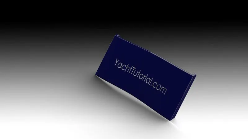
We need to open the Garage Door part which we save while designing the Hull part. Create a sketch on the right plane which has lines in angle and Extrude cut it. Apply shell operation on the given face. Draw a circle on the top face corner of the Door and Extrude cut it to form a hole on it so that the Extruded bose on the hull should be merged with it. Now apply fillets to get a smooth surface and Mirror across the right plane. Now create a new plane with reference to the front plane at an offset distance of 31000 mm.Draw a sketch on the new Plane by drawing Horizontal Center line and insert Text in Text box and cut extrude it. At last give appearance to Door and Text.
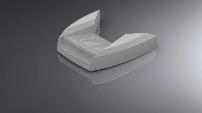
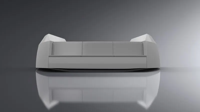
6. FRONT SEAT
This part is placed at the front side of the yacht. Used to sit and feel the moments.
FEATURES USED
Revolve Boss/Base, Extrude cut, Lofted Surface, Swept Surface, Extruded Surface, Filled Surface, Trim Surface & Knit Surfaces, Mirror, Dome, Fillet.
- Swept Surface :- This feature is used to generate curvy solid surfaces which can be open or close profile. To make this we need to select a sketch and a guide path.
To make this part we first need to open the Blueprint setup and save it as Front Seat. Create a top plane and Backplane using the front and bottom plane as a reference. Insert hull part which we have saved as a deck surface for the reference. Create a swept surface using Deck surface and new plane as a reference with a help of splines. Draw two lines to close the surface and use the extrude surface. Now trim the surface and use a fill surface feature to fill the gaps. Draw more sketches to make the part, use trim surface and use surface loft feature, Knit the whole body to form a single body. Draw a new sketch on the right face of the knit body by using lines to create a seat like structure and revolve it to a given angle. Use an extrude cut feature to give a nice look to the seat. Now apply the dome feature on the top of the seat part. Apply fillets and chamfer to the body. Apply appearance and save it.
7. MIDDLE SEAT
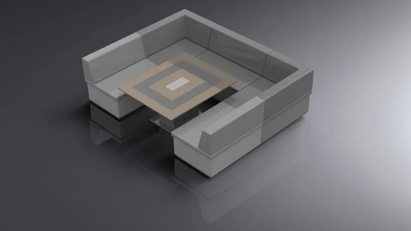
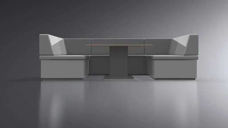
This seat is situated behind the superstructure. It is also used to sit and enjoy the moments.
FEATURES USED
Extrude Boss/Base, Extrude cut, Mirror, chamfers and fillets.
- Chamfers :- It is used to provide a smooth surface on edges.
To make this part we first need to open the Blueprint setup and save it as a Middle Seat. Create a top plane and Backplane using the front and bottom plane as a reference. Insert hull part which we have saved as a deck surface for the reference.Draw a L Shape using lines on face of deck and extrude for lower portion of seat.Create a sketch on above extrude face offset the face and extrude. Create a Plane on above extrude face by offsetting at a distance of 5mm. Sketch on it by drawing lines as per blueprint and extrude. Mirror the bodies across Mid Plane by selecting Knit Surfaces and merging solids. Mirror seats across Mid Plane by de-selecting Knit Surfaces and Merging solids. Create a Table by selecting the deck face using lines and offset entities. Create a Cut Extrude at the top surface of the table and apply fillets. Finally give Appearance to Table & Seats.
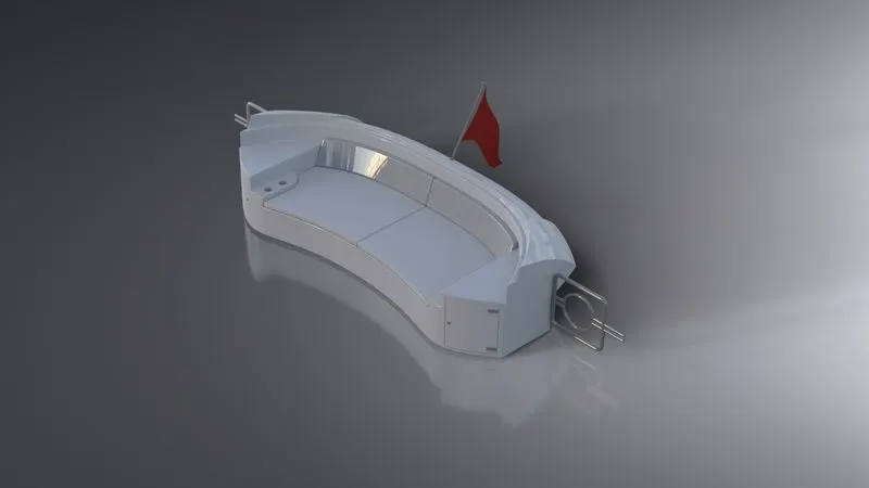
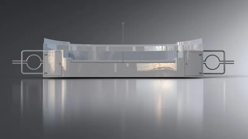
8. REAR SEAT
Rear seat is situated at the rear end of Hull which is also used to sit and enjoy the moments.
FEATURES USED
- Revolve Boss/Bass, Extruded Boss/Base, Extruded Cut, Lofted Surface, Swept Surface, Offset Surface, Ruled Surface, Trim Surface, Knit Surfaces, Mirror, Chamfer and Fillet.
- Offset Surface :- This Feature is used to provide an offset to the surface with given dimensions.
- Ruled surface :- The Sweep type of ruled surface is created by sweeping a straight line in the direction of the vector using the selected edges as guide curves. There are 5 types of ruled surfaces: Tangent to Surface, Normal to surface, Tapered to vector, Perpendicular to vector and Sweep.
- Surface trim :- this feature is used to trim the surface. To use this we need to provide a trim tool. It can be a surface or any sketch and after that we need to give a command that we need to keep the bodies or remove the bodies.
To make this part we first need to open the Blueprint setup and save it as a Rear Seat. Create a top plane and Backplane using the front and bottom plane as a reference. Insert hull part which we have saved as a deck surface for the reference. Create a sketch on mid plane with a blueprint as a reference to make the sketch fully defined. Create a new plane with reference of deck surface face and point on sketch. Draw another sketch on a new plane by drawing a spline. Surface sweep it to form a surface. Now use an offset surface to the faces. Now use trim surface on newly formed surface to remove unwanted surface. Then use a ruled surface feature to give proper tangency to the surface face and extend the surface. Trim the unnecessary surface by using a new sketch as a trim tool. Knit the surfaces to form a single surface structure. Draw two new planes and sketch on those planes respectively. Surface sweep it. Extend the newly formed sketch and trim the unnecessary surface so that we don't have any gap between and knit them. Draw a new sketch on the deck surface and do the same procedure. Create a few Planes and draw sketches by using convert entities and splines. Do Surface sweep using these sketches. Extend the Surface and trim the unwanted surfaces using surface trim and Knit them. Create few 3D Sketches and do surface loft. Create a sketch on deck face by converting respective entities and splines with midpoint, Extrude it. Now create a sketch on deck surface by converting entities and a line with midpoint spline to get the surface for seating and extrude it. Do as per the tutorial. Now extrude cuts for drawers by using sketches made on the front plane. Create a new plane and sketch on that plane to get edges and handle to the drawer. Extrude it from the surface. Use an appropriate face to offset features to make a seat. Extrude it. Now draw a new sketch on a plane for making a light. Extrude it from the surface. Apply fillets and chamfers to the bodies and use knit surface option to form a single body. For locking the gates. Create few planes as per requirement and draw sketches accordingly using circle and line. Using these sketches sweep and mirror it. Now mirror the bodies across the mid plane except the locking gate. We need to mirror the locking gate using another mirror option by deselecting the knit surface and merge solid options. For flag stand draw a line at an angle and use revolved boss extrude. For Flag Create four 3D Sketches by drawing splines with midpoints in each sketch and loft the surface.Finally give appearance to seats, surface, flag, hand resting, lights, drawers and gate.Fillets and chamfers are given to the profile to get a smooth curve.
- SUPERSTRUCTURE
A superstructure is an extended construction of any building or platform that rises above the rest of the building or platform in a distinct manner. The word comes from a combination of two Latin words, the Latin prefix ‘super’ means in addition or above or in excess of, whereas the stem word ‘structure’ means to build or to heap up. Thus, superstructure means to add a construction to an already existing structure. In ships this is the name given to the part of the ship that emerges from the deck. However any mast, sails, any armaments or arsenal are not included in this category.
FEATURES USED
Extruded Boss/Base, Extruded cut, Projected curve, Split line, Delete faces, Mirror, Swept Boss/Base, Lofted Surface, Extend Surface, Filled Surface, Extruded Surface, Ruled Surface, Trim Surface & Knit Surfaces, Chamfer & Fillet
- Delete Face :- Used to delete the faces of solid bodies to make them surface or delete faces from surface bodies. It is a very useful feature
- Extend Surface :- It is used to extend an end surface to fill the gaps between surfaces.
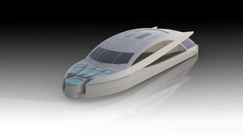
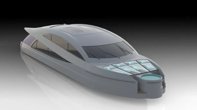
To make this part we first need to open the Blueprint setup and save it as a Superstructure. Create a top plane and Backplane using the front and bottom plane as a reference. Insert hull part which we have saved as a deck surface for the reference. Create a sketch on a deck surface using a line and a spline and use extrude surface feature to 600 mm upward. Create a new plane on the edge of the created surface. Draw a line and 3D sketch by converting entities on the top edge of the newly created surface. Now use Ruled surface with tapered to vector type and apply the given dimension. Select internal edge of surface as a reference and give 5 degree angle deflection. Trim the ruled surface and Knit all surfaces. Create one more Projected Curve by drawing two sketches on respective Planes using Splines and lines which is further used in creating Lofted Surface repeat the same and create another curve. Create Surface loft and surface Fill by Creating Six 3D sketches. Trim the unwanted surface by drawing another 3D sketch. Create one more surface sweep by drawing sketches on the created Plane using line and apply pierce relation with extruded surface. A 3D sketch by convetering Outer surface as entities. Surface sweep the sketch and Trim an unwanted surface and knit the surfaces.. For the top portion of a Superstructure Sketch on mid plane convert entities to make a sketch and use extrude surface feature. Using a 3D sketch, draw another sketch and fill the surface. Now draw a sketch on the face of the previous surface and trim that face using the new sketch as a trim tool. Use the surface loft and fill the portion behind the side window and knit them all. Create a few more planes and sketches to completely make the side window, trim the unwanted sketch and knit them all. For the front portion of superstructure Draw a sketch on Mid Plane by converting respective edges and do surface extrude. Trim extra surfaces and Knit all together. Select new sketch on Deck surface and use extrude surface feature. Now make some more sketches use surface extend, surface sweep, surface trime to make the front portion of Superstructure. Select the deck surface and create a by drawing a circle at a distance from above surface extrude. Extrude it and draw a circle on the extruded face to perform the cut extrude. Draw two more circles on extruded face which are again to be extruded. Apply fillets to respective edges. Inorder to remove extra portion draw a rectangle on deck surface do cut extrude. Use the Delete face option to remove the face to make it surface. Now create a new plane with reference to the front plane and vertex point. Create a new sketch on that plane and extrude it. For steps draw a few horizontal and vertical lines accordingly and extrude them. Trim the Extra Surfaces in order to make it Solid, Sketch on deck surface by drawing a horizontal line and do surface extrude. Trim the extra surfaces and Create Solid by knitting the surfaces. Now use surface trim feature and trim the deck surface and knit them. Draw a new sketch on the top plane and extrude it. Now use superstructure as a trim tool and remove unwanted surfaces. Now knit the surface click the merge entities and create a solid option. For Mattress create a Surface Offset at Front end and Trim unwanted surface and thicken the surface by selecting respective faces. Create a cut extrude and apply domes and fillets to them. Now for making railings create a new plane, draw sketches using plane, spline, circle sweep it. For the rear door create a cut extrude by offsetting rear face inwards. Draw a L shape and extrude it for handle creation. Now for the front glass create a sketch on the front plane, offset it and use cut extrude feature. Sketch on required face by drawing two vertical lines and converting top and bottom edges of glass. Trim unwanted entities and do Extrude. Create a new sketch on the plane draw line and spline to make it defined. Extrude it from the face, now the frame is made for the top glass. Create a new sketch on the top plane and use cut extrude. Draw similar glass frames for other glasses too. For the Rear portion , draw a sketch on Midplane Offsetting respective faces and do a split line. Now to create a frame for rear glass create a sketch on a plane and extrude it from the surface to give value. Now create a new plane with reference to mid plane and do the same for side glasses. Water body is made by making a sketch on a mid plane as given reference, using the extrude surface option. For wiper holders create a Sketch on top face of Super structure by drawing one circle and half circle. Extrude them. Mirror the bodies across Midplane. Create an Offset Surface by selecting the rear portion of Top face of Super Structure and rename it as Radar Mast Reference. Create a Rectangle on the respective plane and do Boss extrude. Repeat two more times at respective places. Apply Chamfer and offset the Side faces and do cut extrude. Similarly do it for remaining Wipers. Draw a 3D sketch by drawing a line connecting the holder and wiper, extruding it which acts as a connecting rod. Repeat for remaining ones. Give fillets and chamfers for required edges to give them a smooth surface. Apply required appearance to frames, wiper, window, doors, mattress, water body, glass, and superstructure. Apply decals to the stairs.
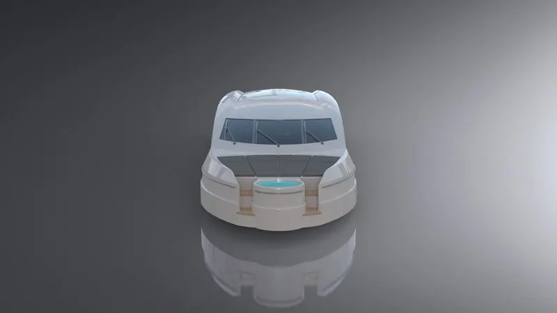
- RADAR MAST
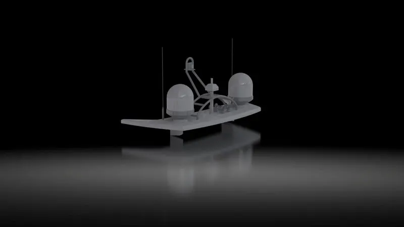
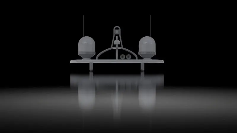
Marine radars are X band or S band radars on ships, used to detect other ships and land obstacles, to provide bearing and distance for collition avoidence and navigation at sea. They are electronic navigation instruments that use a rotating antenna to sweep a narrow beam of microwave around the water surface surrounding the ship to the horizon, detecting targets by microwaves reflected from them, generating a picture of the ship's surroundings on a display screen.
Radar is a vital navigation component for safety at sea and near the shore. Captains need to be able to maneuver their ships within feet in the worst of conditions and to be able to navigate "blind", when there is no visibility at night.
FEATURES USED
Extruded Boss/Base, Revolved Boss/Base, Projected curve, Mirror, Swept Boss/Base, Chamfer & Fillet
To make this part we first need to open the Blueprint setup and save it as a Radar Mast. Create a top plane and Backplane using the front and bottom plane as a reference. Insert Superstructure part which we have saved as a Radar Mast reference. Now create a sketch on mid plane with reference to the radar mast, draw a horizontal line at a distance of 160 mm above the radar mast reference. Create a new plane. Draw 4 splines and a line as per Blueprint and extrude it on the created plane. Apply fillets to the edges. Create a new plane with the front plane as a reference and offset it to 20950 mm. Draw a sketch on a new plane and revolve it to get a radar indicator, apply fillets. Create a new sketch on the face of the newly extruded surface, draw a circle and extrude it to a given dimension. Draw a circle on the extruded face,do the same for one more time and extrude it. Apply fillets. Draw two new planes and sketch on the plane to make swept boss base extrude. Mirror the newly created swept across plane 2. Draw 3 circles on plane 2 and extrude them with a mid plane option on both sides at 500 mm. Create a Projected curve as per requirement by drawing sketches on respective Planes. Draw the circle at the edge of projected curves and sweep it. Draw some extra sketches to fulfil the blueprint setup, extrude them and mirror them as required. For horn draw a few lines and splines as per blueprint and use revolve boss bass. Apply Dome to one end and shell to other end. Now mirror bodies except the horn portion across mid plane. Now to give support to the horn, draw a slot on the face of the first extrude and use the extrude boss feature up to the next surface. Now create a new plane using a reference of newly extruded bodies right face with an offset on 130mm. Mirror the horn across that new plane. Apply fillets and chamfers as required to provide a smooth surface. At last give appearance to the indicator, antena, horn and radar mast.
- ASSEMBLING OF SUNSEEKER PREDATOR YACHT
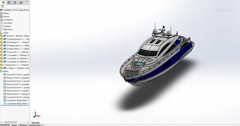
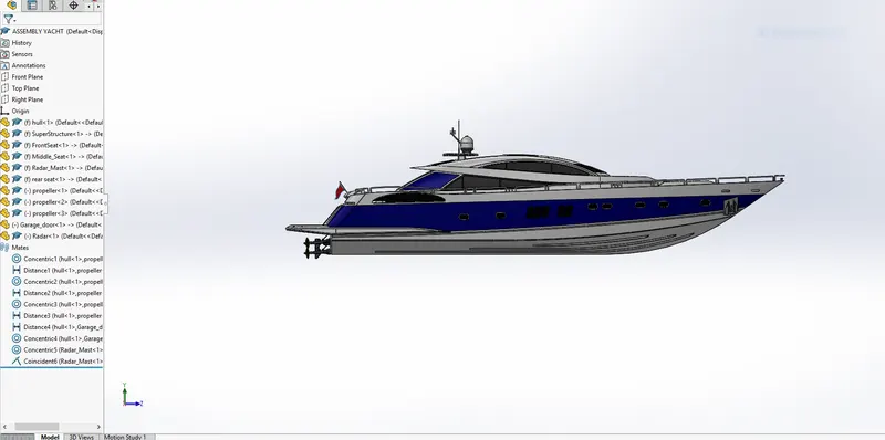
After part designing and modelling and giving appropriate appearance to the body, Now we need to do assembling of the predator Yacht to make the final product.
To start assembling we need to start solidworks and open the assembly file. After opening a part has to be opened one by one. For the assembling of Yacht first a Hull part has to be opened and it will be the reference to all other bodies of an assembly.
After inserting a Hull Part, Superstructure is opened and by selecting ok option this will automatically attached to the Hull. Repeat the same and open each part one by one.
Now the other parts such as Front Seat, Middle Seat, Rear Seat, Garage Door, Propeller, Radar Mast and Radar are opened. Some of the parts will require Mates to fix their position.
In this assembly Only Rear seat, Radar and Propeller are located using coincident and Concentric relations mates with respective Parts. Other Parts are already fixed due to the reference condition we have applied.
- RENDERING OF ASSEMBLY
Rendering is the process of generating an image from a model, by means of a software program.
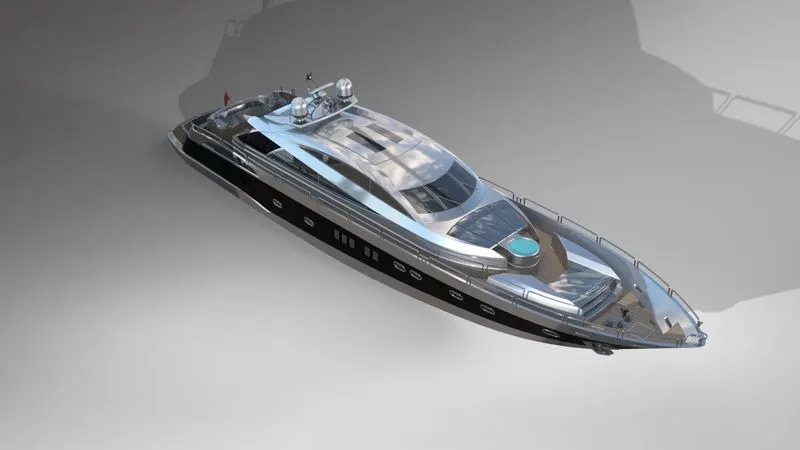
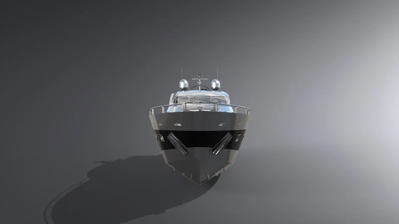
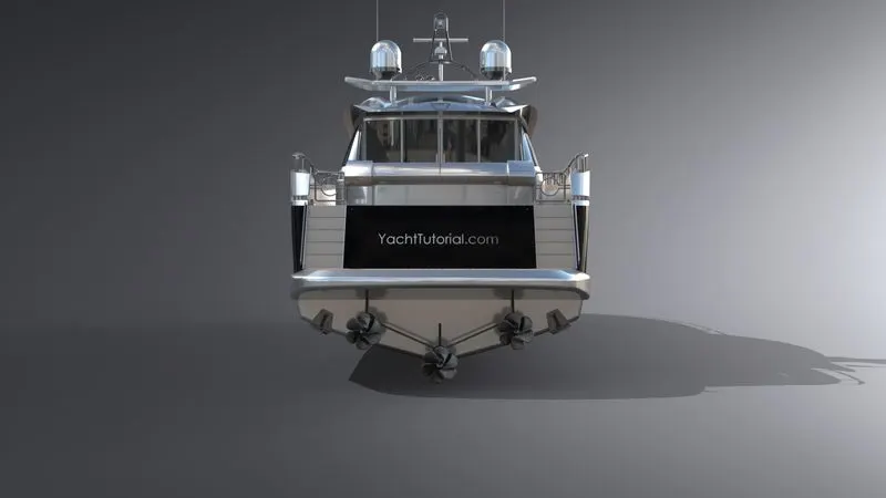
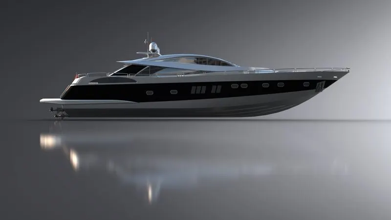
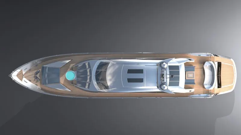
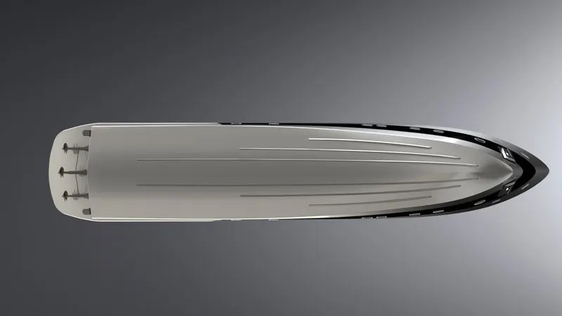
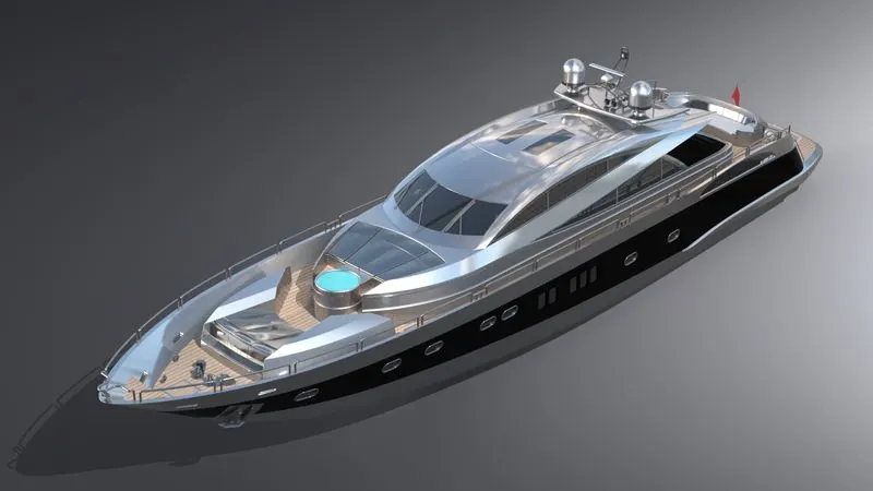
After the assembling of Predator Yacht a rendering is done to give a realistic look and nice finish to our assembly.
After the application of the decals is completed the assembly is taken into Solid Works Visualize or into the Photo-View 360 for rendering. Later this assembly is gone through different aspects such as adding scenes, camera, file libraries and applying new appearances as required. The main function here is to apply backplates inside the scenes option. Photorealistic model is obtained using rendering options. By applying this process we can easily obtain a rendered Sunseeker Predator Yacht with realistic images.
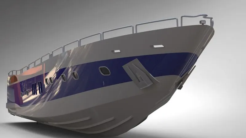
SOME RENDERED IMAGES OF SUNSEEKER PREDATOR YACHT ARE GIVEN BELOW
CONCLUSION :-
- All the parts of the Sunseeker Predator Yacht are modelled.
- The assembling of the Sunseeker Predator Yacht is completed inside the assembly environment.
- The image was rendered by using Photo view 360 and Solidworks Visualize.
I specially thank my mentor Mr. Soundar Rajan for guiding me and helping me with the difficulties I face during completion of this project.