Advanced Sheet Metal Design Using NX Cad Challenge_2_Box Assembly
Designing of Box Assembly Using Sheet Metal
In Siemens NX Cad
OBJECTIVE:
- In this project we are going to design an Box Assembly using sheet metal in NX CAD
- In this project we have learned step by step procedure to design a “Sheet Metal Box Assembly”.
INTRODUCTION:
Sheet metal is metal made by the industries to make thin, flat piece. In NX CAD sheet metal application is used in Machineries, Automobile industries, Aerospace industries, etc.
The container having flat base which can be in rectangular or square in shape, covering on all the sides and packed from the top side meanwhile all six sides are packed and has a space inside the body used for storage is called as Box.
In this Sheet Metal Box Assembly there are three main parts. They are listed below.
- Main Box
- Cover
- Hinge
All this parts are designed using NX CAD Sheet metal.
DESIGN METHODOLOGY:
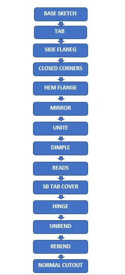
DESCRIPTION:
TYPES OF FEATURES USED ARE GIVEN BELOW
- TAB: This feature is used to create a solid surface or extruded surface with a thickness.
- FLANGE: By using this command we can add a flat flange to the model at a required angle.
- CLOSED CORNER: The open corners present in the design which are between the adjacent walls can be closed using this operation.
- HEM FLANGE: Modifies the model by folding the edge of a sheet metal flange over onto itself for the purpose of safe handling or to increase edge stiffness.
- MIRROR: This feature is used to mirror the feature or bodies across respective planes.
- UNITE: This feature is used to combine the two different mirror bodies to single body.
- DIMPLE: This feature is used to create a lifted area on the sheet metal. To use this feature we first need to sketch on the surface of model and provide needed direction to the dimple. There are different properties in this feature to make a required dimple.
- UNBEND: This command is used to unbend the sheet metal to perform deferent operations which can be operated using unbend feature only.
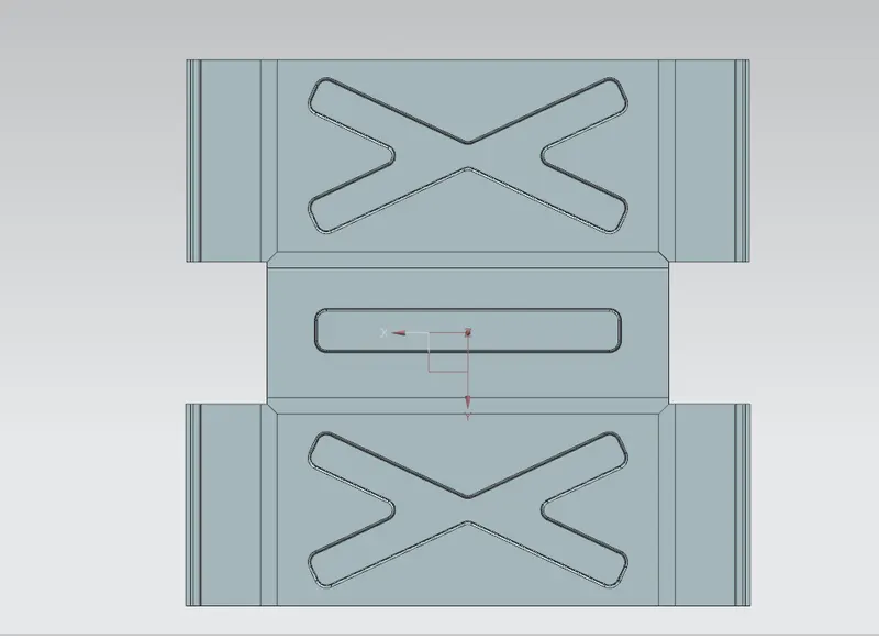
- REBEND: After finishing all these operation the sheet metal parts need to rebend to its previous bend state. After rebending we can see that all the operation we have performed after unbend feature. They can now also been seen without any change in the parameters.
- BEAD: This command is used to lifts the material along the contour of the sketch that simulates the stamping tool.
- DATUM PLANE: The extra plane is created along the required parameters to construct other features.
- BREAK CORNER: This command is used to bend the sheet metal as per the required shape and angle.
- NORMAL CUTOUT: This command is used to remove the material from a model. The cut made by using this feature will be perpendicular to the face.
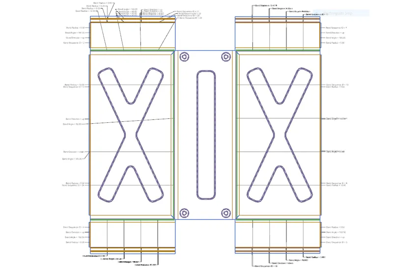
- FLAT PATTERN: This feature is used to create a 2D sketch on the sheet. The flattened model is necessary for the manufacturing process. This involved all the detailed dimensions required for manufacturing.
PROCEDURE:
- Create a new sketch on the XY plane with the help of rectangle.
- Use Tab feature to add thickness to the base.
- Add four flanges to the created base with required dimensions.
- Use closed corner feature to close the corner present in the adjacent walls.
- Now create another flange so that we can use Hem Flange.
- Now arrange the hem flange to that we should get the required shape. While using this feature we have to select open, than in insert option use bent outside, keep the bend radius to .5mm, flange length to 5mm and select OK.
- Now use mirror option and then unite them to for single body.
- Draw a new sketch on the side flange to make a Dimple.
- Now mirror that new dimple across the XZ plane.
- Now create a new sketch on the bottom of the box.
- Make a Dimple, but this time the dimple will be inside the box.
- Now unbend and rebend the Model.
- Now make a new sketch on the bottom of the box to create a bead.
- After creating a bead use Mirror feature to get 4 more Beads at 4 corners. For this we need to mirror the feature across respective planes.
- Now again use Hem flange feature on the top corners of the box.
- Now create a new Plane using Datum Plane option which has an offset value of 203mm from the bottom plane (XY).
- Now create new sketch on the new plane by taking the reference of boundary present at top of the box.
- Use Tab feature to seal the Box Assembly.
- Add few more flanges to the newly form tab.
- Now to create a hinge to the box, create a new sketch on the side of the box and use Break corner feature. Provide a flange to the newly formed body as required.
- Use Hem flange to get the 325 degree Angle to the Hem. Set bend radius to 5mm, keep bend outside and open loop press OK.
- Now unbend the body to make a normal cutout.
- Then rebend it as before to get a desired body.
- Now use Mirror feature across the XZ plane.
- Create a new sketch using rectangle on the top of the box and again use tab feature. Now add break corner to the tab on both the sides. Again repeat the same procedure by using Unbend, Rebend, Flange, Hem flange, Normal cut out to finish the design of Box Assembly.
- At last use flat pattern feature.
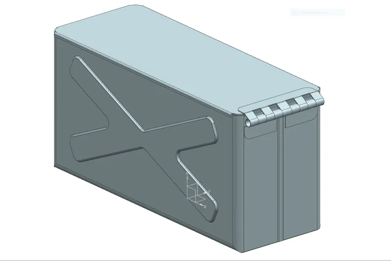
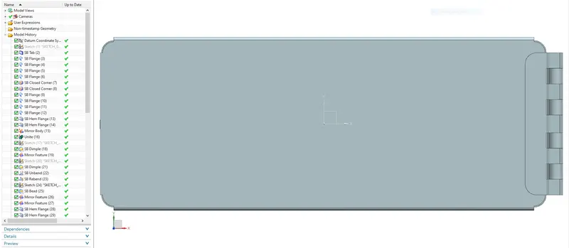
SOME IMAGES OF THE BOX ASSEMBLY ARE GIVEN BELOW:
- ISOMETRIC VIEW
- TOP VIEW
- SIDE VIEW
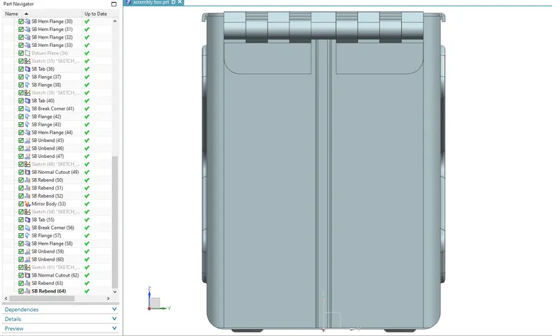
- FRONT VIEW
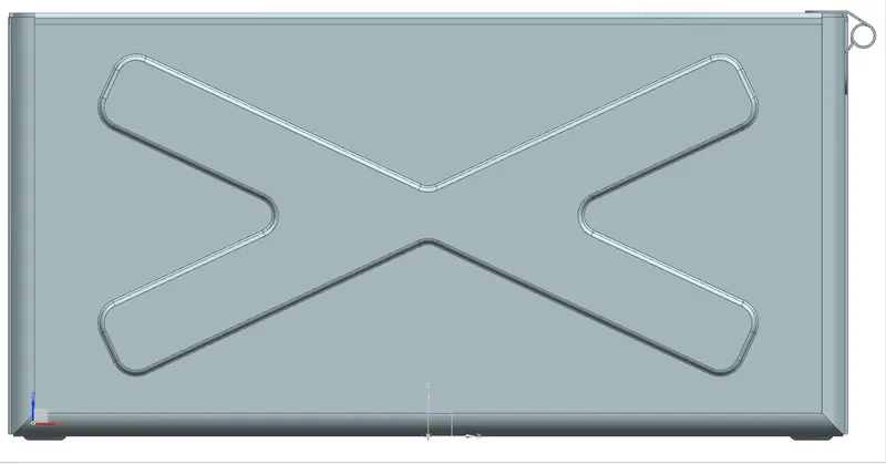
- BOTTOM VIEW
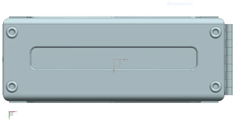
- COLORED ISOMETRIC VIEW
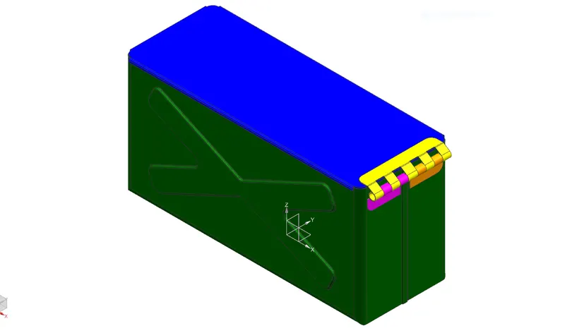
- FLAT PATTERN
THANK YOU
NAME: AVINASH LANJEWAR