Advanced Sheet Metal Design Using NX Cad Challenge_1_Casing Design
CASING DESIGN IN NX SHEET METAL
OBJECTIVE
- To design a casing using sheet metal application in Siemens NX CAD.
- Learning NX CAD Interface and basic sheet metal features.
- Learn how to draft a sketch using NX CAD.
INTRODUCTION
Sheet metal is metal made by the industries to make thin, flat piece. In NX CAD sheet metal application is used in Machineries, Automobile industries, Aerospace industries, etc. The outermost layer to protect internal body is called as casing. It can be located outside or inside the body to protect any gadget. . Material used in designing of casing are Steel, Aluminium, Brass, Copper, Titanium, etc.
DESIGN METHODOLOGY
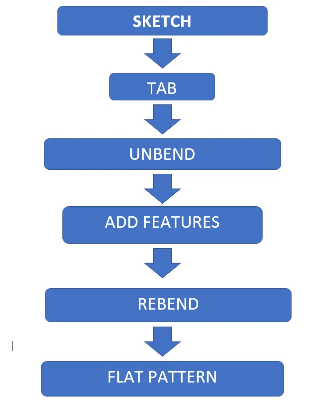
DISCRIPTION
TYPES OF FEATURES USED ARE GIVEN BELOW
TAB: This feature is used to create a solid surface or extruded surface with a thickness.
NORMAL CUTOUT: This command is used to remove the material from a model. The cut made by using this feature will be perpendicular to the face.
BENDING: This command is used to bend the sheet metal as per the required shape and angle.
FLANGE: By using this command we can add a flat flange to the model at a required angle.
BREAK CORNER: This command is used to create a smooth corners to the edges.
UNBEND: This command is used to unbend the sheet metal to perform deferent operations which can be operated using unbend feature only.
HOLE: It is a type of punch that removes the material throw-out the sheet metal with a precision. In this we can select different types of holes as per the requirement.
STUDIO SPLINE: This feature is used to create a spline. This have deferent options to create spline. Bye the use of MOVE CURES option we can move the curve to an angle.
DIMPLE: This feature is used to create a lifted area on the sheet metal. To use this feature we first need to sketch on the surface of model and provide needed direction to the dimple. There are different properties in this feature to make a required dimple.
MIRROR: This feature is used to mirror the feature or bodies across desired planes.
BEAD: This command is used to lifts the material along the contour of the sketch that simulates the stamping tool.
REBEND: After finishing all these operation the sheet metal parts need to rebend to its previous bend state. After rebending we can see that all the operation we have performed after unbend feature. They can now also been seen without any change in the parameters.
FLAT PATTERN: This feature is used to create a 2D sketch on the sheet. The flattened model is necessary for the manufacturing process. This involved all the detailed dimensions required for manufacturing.
By creating a new Sheet Metal model and saving it as a Casing.
The sketch is drawn in the XY plane using rectangle.
Use Tab command to create a base metal body with 1mm Thickness.
Now make a new sketch on that thickened surface and use normal cutout Feature.
Create another sketch in same face by drawing two line with required dimension and use bending feature.
Now add flanged to the newly bended surface with required dimensions.
Now use break corner feature to give smooth curves to the edges.
Now unbend the sheet metal to perform several operations.
Create a four holes on four corners of the sheet metal.
Now create a new sketch with given dimensions and use spline studio feature. To create a curve select all the 16 points on the respected sketch. Set the type to BY POLES. Set a degree to 3 and select close option.
Now to move the curve use move curve option and select the curve, give a motion to the angle, specify the origin to (0,0,0), now give 45 degree angle.
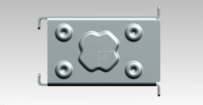
Now add dimple by selecting the curve. In a dimple feature set depth to 1mm, Depth reference inside, Side wall is material inside. And apply it.
Now add bead to the model by creating a sketch on the surface. Mirror it to respected planes.
Now rebend all the surfaces in the reverse sequence.
Now at last use flat pattern feature. Get a draft image and save the draft file.
ISOMETRIC VIEW
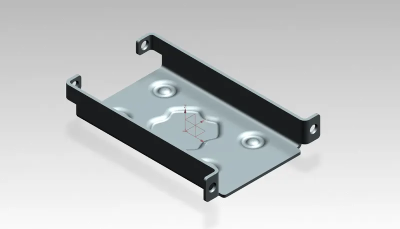
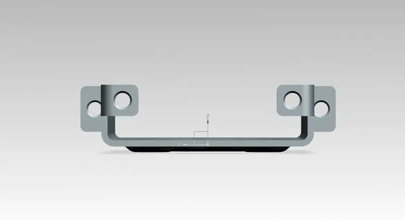
FRONT VIEW

SIDE VIEW
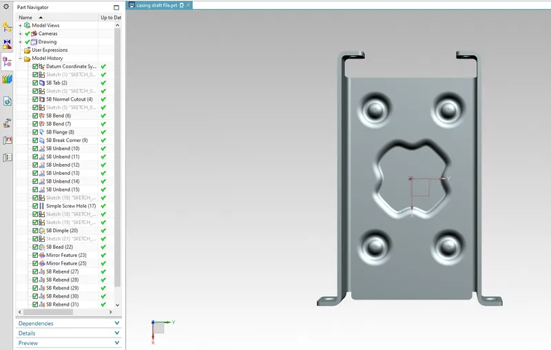
TOP VIEW
BOTTOM VIEW
NAME: AVINASH LANJEWAR