Advanced Sheet Metal Design Using NX Cad Challenge_7_ Metal bracket-II
SHEET METAL DESIGN OF METAL BRACKET
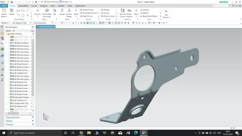
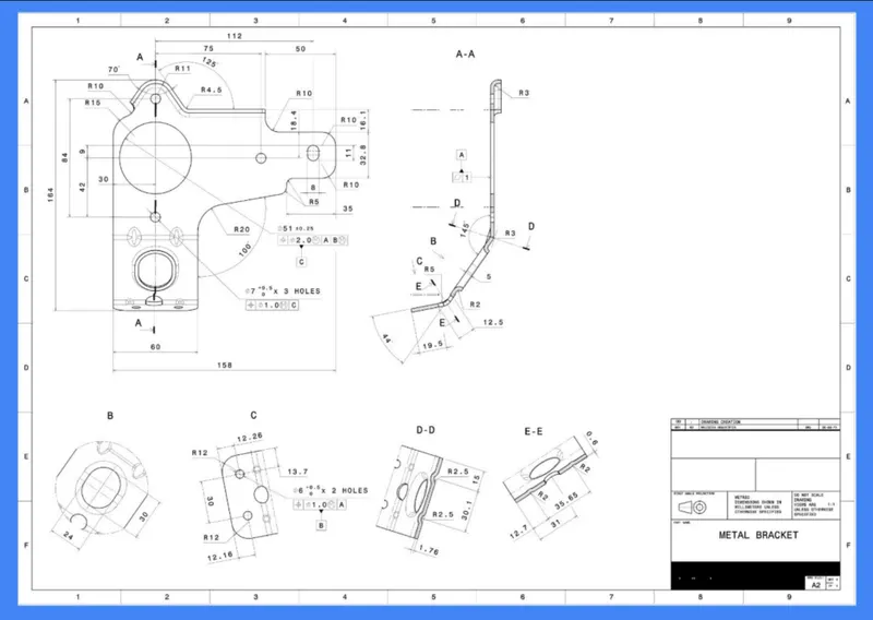
Objective To create a metal bracket using NX CAD from 2d drawing.
-
-
DESING METHODOLOGY
FEATURES USED
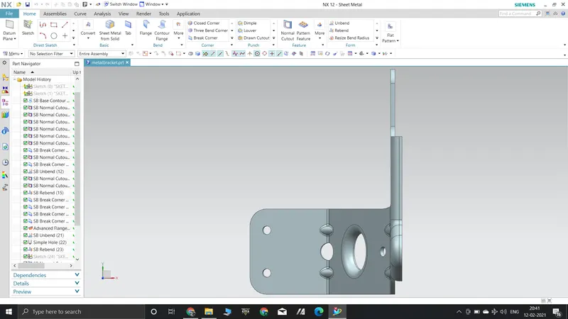
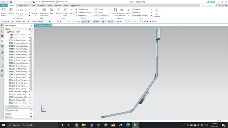
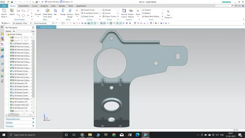
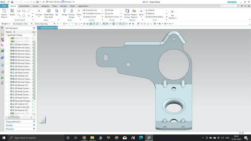
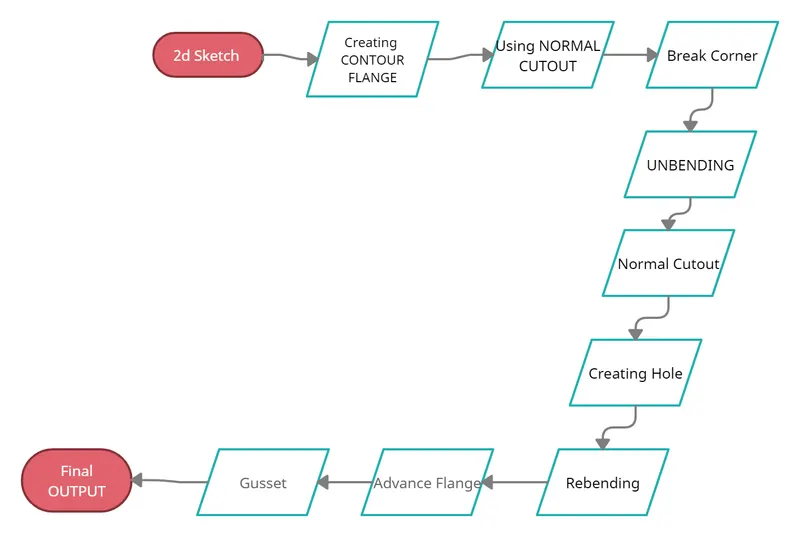
- Contour Flange: Creates a base feature by extruding the sketch along a vector or add material by sweeping the sketch along an edge.
- Break Corners: This feature makes sharp edges to smooth round shape or to chamfer shape.
- Normal Cut-Out: It helps to cut material by projecting a sketch onto the model, cutting perpendicular to the face.
- Unbend: This feature helps to unbend the bent shapes to a flat pattern.
- Hole: Creates a hole on the selected location on the sheet metal part.
- Rebend: This command helps to rebend the sheet metal part to its original form.
- Advanced Flange: Add a flange along an edge using a bend angle or a reference face. The edge and reference face can be curved.
- Gusset: Creates a stiffening gusset on the part.
- Flat Pattern: It is used to represent the whole component in 2D form. This flat pattern also shows entire features with dimensions.
- Drafting: Drafting is creating a technical drawing into a sheet, communicating about the dimensions and view of components. The draft helps the manufacturing and production department to know about the product design in a 2D format.