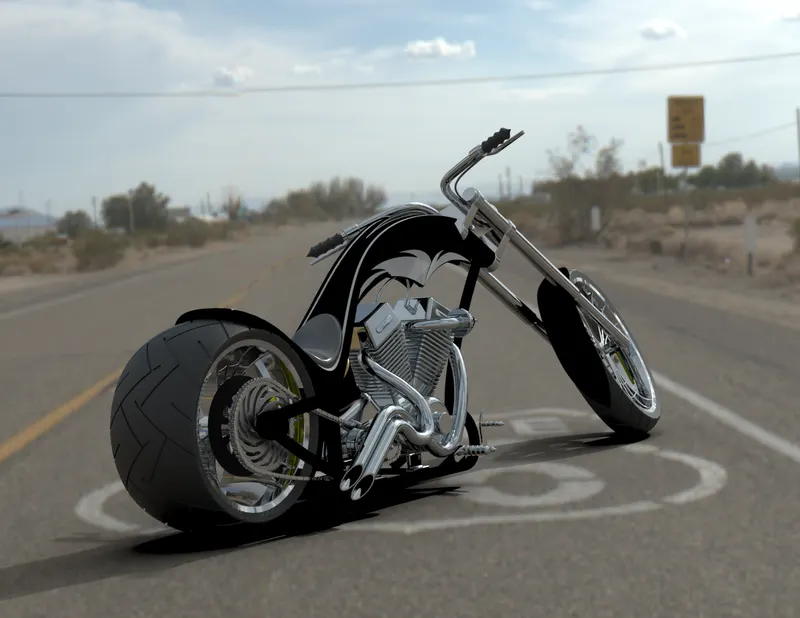
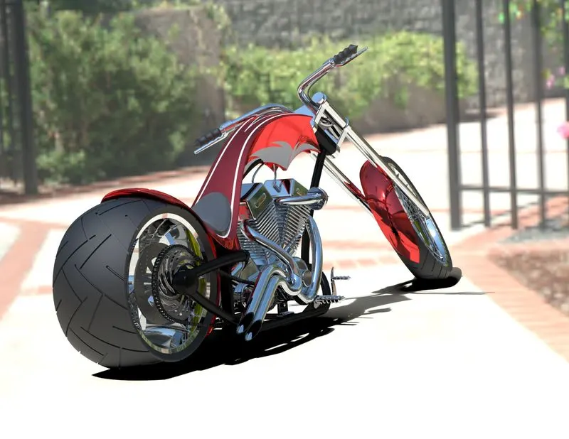
Photo Realistic Rendering
Designing an American Chopper
Objective :
To design an American Chopper using Solidworks.
Intro :
This report explains designing of an American Chopper starting from part modelling and assembling in Solidworks 2019 to final rendering using Solidworks Visualize 2019.
Methodology :
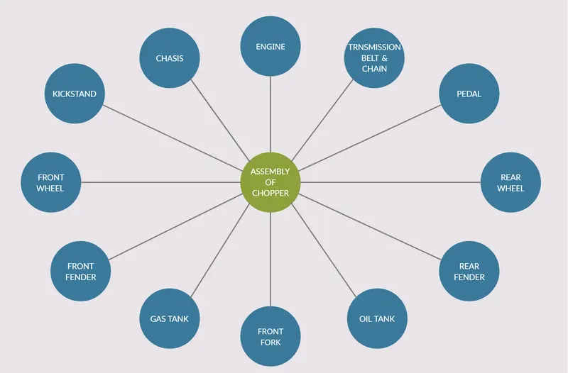
All the parts for the assembly of chopper were made separately first and then were assembled in Solidworks.
Features used :
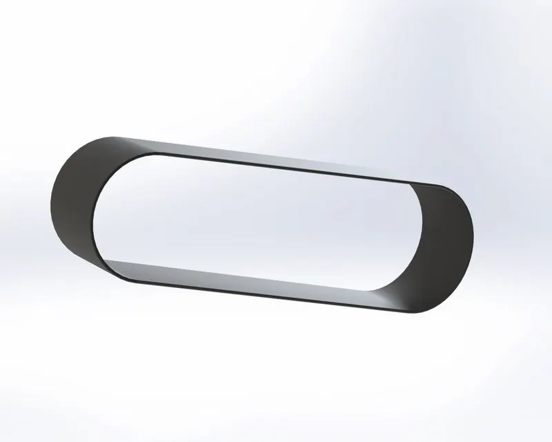
1. Transmission belt -
While designing transmission belt, following features were used -
1. Sketch - Sketch is a two dimensional representation of the model we are creating.
2. Extrude - Extrude feature extrudes the 2d sketch we created into a 3d body as per the sketch dimensions.
3. Fillet - Fillet gives a round curved surface on the selected face or edge of the model.
4. Offset - Offset creates an exact copy of sketch on the same plane at some specified distance.
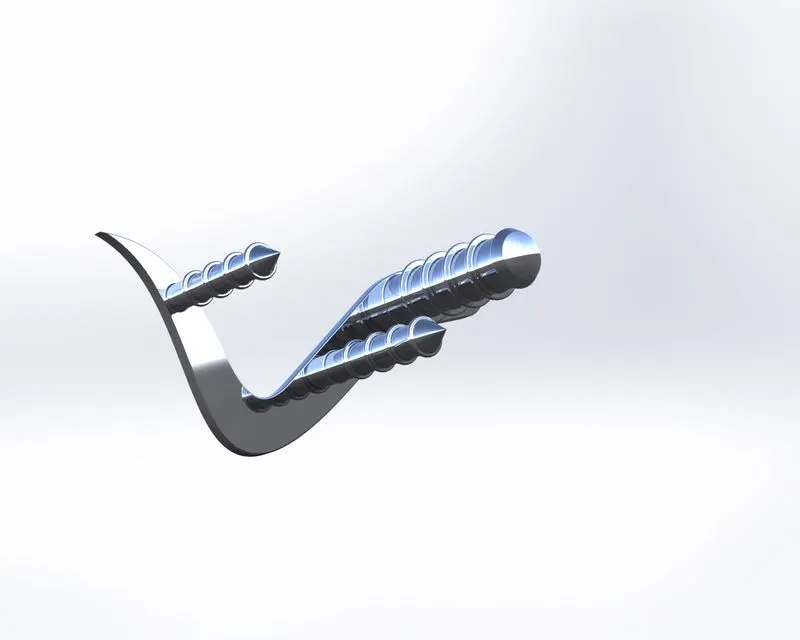
2. Pedal -
While designing pedal, following features were used -
- Sketch
- Extrude
- Fillet
- Linear pattern
- Dome
- Chamfer
- Appearances
Chamfer - Chamfer creates a cut on the edge or corner of model as per specified distance and angle.
Dome - Dome create a dome shape on the selected face of the model as per the given dimensions.
Linear Pattern - The features/bodies are patterned linearly. Pattern is a kind tool like Array available in AutoCAD.
3. Kickstand -
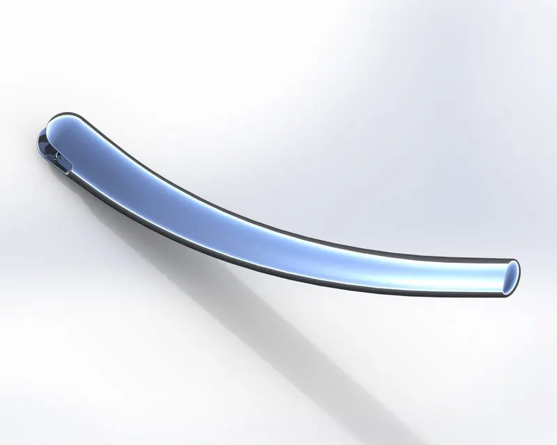
Features used to create KickStand:
- Sketch
- Loft
- Dome
- Extrude Boss
- Extrude cut
- Fillet
- Split
- Appearances
Loft - The loft feature in SOLIDWORKS allows you to generate complex geometry in a single feature. It does this by interpolating surfaces between various cross-sections of a model. These cross-sections can be sketches, faces or edges.
Extrude cut - Extrude cut removes material from the 3D model. It is just the opposite to extrude boss/base feature, because it cuts a sketch profile while extruding. Y
Split - The SOLIDWORKS Split Line tool is used to project an entity (sketch, solid, surface, face, plane or surface spline) onto other surfaces or curved/planar faces. You are also able to split faces on multiple bodies with one command.
4. Front Fender -
features used to create Front Fender:
- Sketch
- Offset Entities
- Trim entities
- Revolve
- Dynamic mirror
- Split
- Appearances
Trim entities - Select the trim type based on the entities you want to trim or extend. All trim types are available with 2D sketches and 2D sketches on 3D planes.
Revolve - To create a revolve feature: Create a sketch that contains one or more profiles and a centerline, line, or edge to use as the axis around which the feature revolve can be used.
Dynamic mirror - By using dynamic mirror, while you sketch the entities, they can be mirrored about the pre-selected sketch entity.
5. Rear Fender -
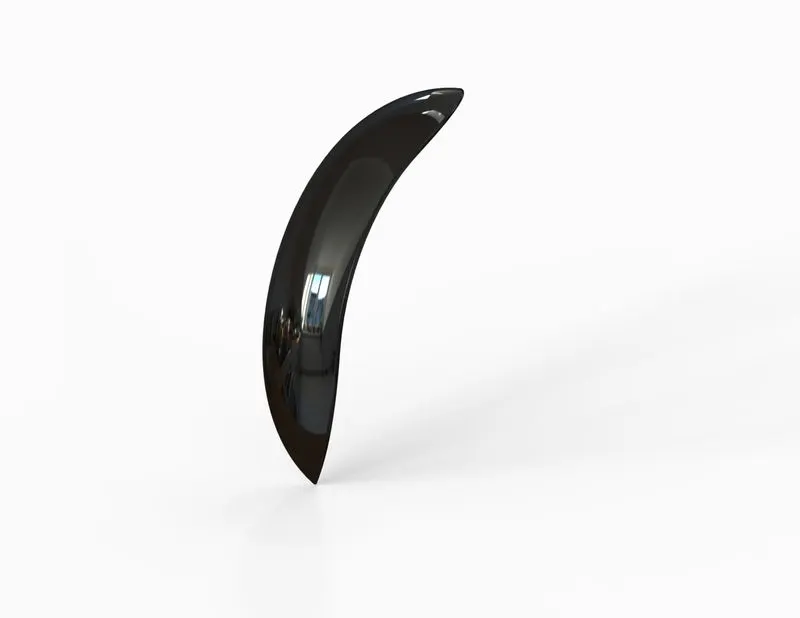
Features used to create Rear Fender:
- Sketch
- Offset Entities
- Trim entities
- Revolve
- Appearances
Appearances - An Appearance defines the visual properties of a model, including colour, texture and material.
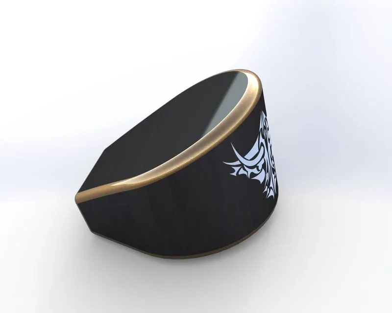
6. Oil tank -
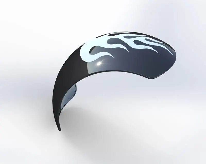
Features used to create Oil Tank:
- Sketch
- Boss Extrude
- Combine
- Fillet
- Shell
- Appearances
Combine - Combine feature is used to manually combine the two bodies into the one body.
Shell - The Shell feature is used to define the thickness of thin and thick shell elements.
7. Chain -
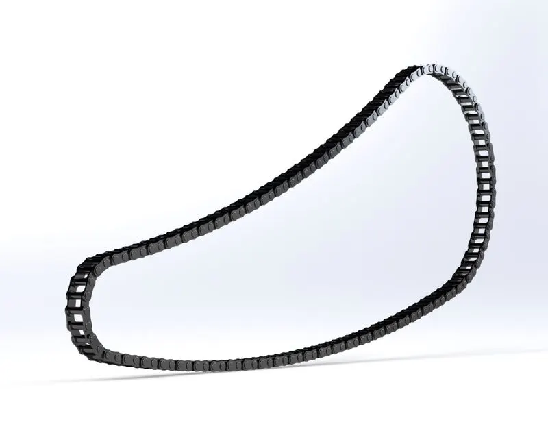
Features used to create the Chain:
- Sketch
- Trim
- Fillet
- Blocks
- Extrude
- Patterns
- Appearances
Patterns - The Curve Driven Pattern tool allows us to create patterns along a planar or 3D curve. We can base our pattern on an open curve, or a closed curve, like a circle.
8. Front Wheel -
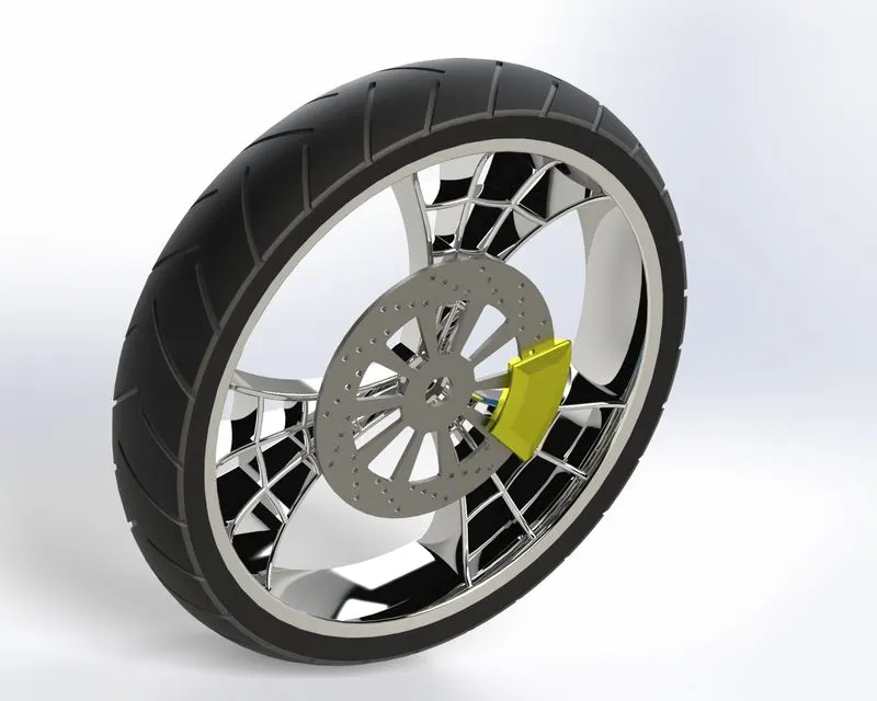
Features used to create the Front Wheel:
- Sketch
- Revolve
- Trim
- Fillet Entities
- Boss/Base Extrude
- Revolve Cut
- Linear pattern
- Chamfer
- Fillet Features
- Cut Extrude
- Circular Pattern
- Appearances
9. Rear Wheel -
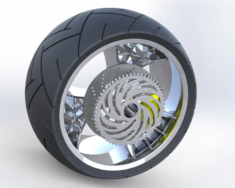
Features used to create the Rear Wheel:
- Sketch
- Revolve
- Trim
- Fillet Entities
- Boss/Base Extrude
- Planes
- Revolve Cut
- Linear pattern
- Chamfer
- Fillet Features
- Cut Extrude
- Circular Pattern
- Appearances
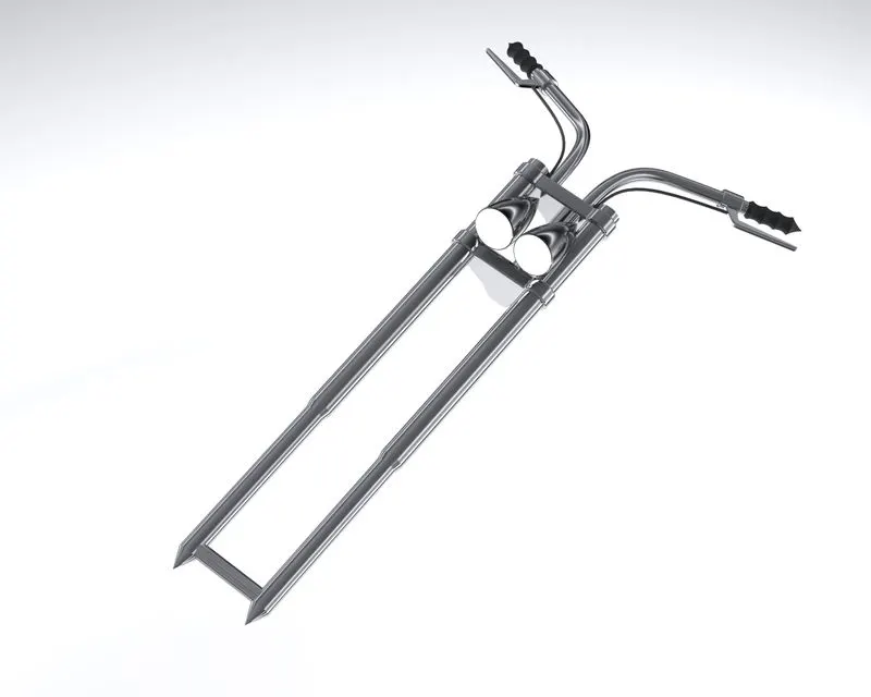
10. Front Fork
Features used to create the Front Fork:
- Sketch
- Extrude
- Trim
- Revolve
- Split
- Plane
- Convert entities
- Move/copy Body
- Dome
- Mirror
- Combine
- Curve (Project Curve)
- Sweep
- Appearance
Move/copy Body - Move/ Copy body is used to move/copy the body from one place to other places.
Mirror - By using mirror feature, we can mirror body or part to the other side about the plane.
Project Curve - Project curve is the kind of 3D curve which is projected based on the two different 2D sketches.
Sweep - By Sweep feature, we can create a shape by moving a 2D sketch Profile along a 2D or 3D sketch Path.
11. Chasis -
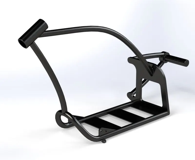
Features used to create the Chassis
- Sketch
- Offset
- Convert entities
- Project Curve
- Trim
- Plane
- Sweep
- Split
- Revolve
- Cut Extrude
- Fillet
- Combine
- Appearance
12. Engine -
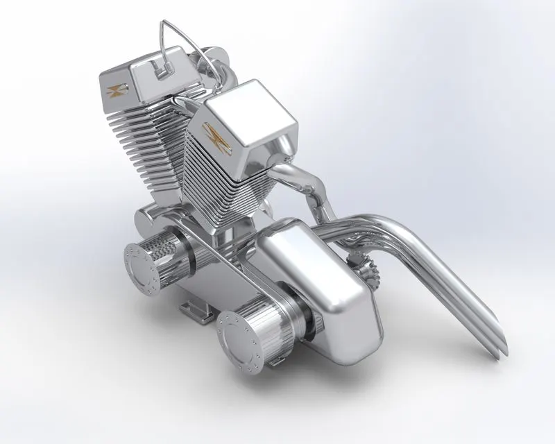
Features used to create the Engine:
- Sketch
- Convert entities
- Trim
- Revolve
- Boss extrude
- Cut extrude
- Offset
- Dome
- Fillet
- Project curve
- Composite curve
- Sweep
- Mirror
- Circular Pattern
- Split
13. Gas Tank -
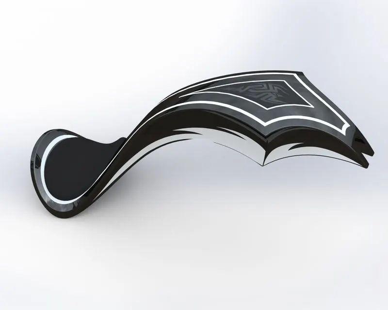
Features used to create the Gas Tank:
- Sketch
- Trim
- Project curve
- Convert entities
- Sweep Surface
- Loft Surface
- Fill surface
- Surface trim
- Surface knit
- Sweep cut
- Fillet
- Appearances
Loft Surface - Loft Surfaces are surfaces generated by multiple 3D Curves or existing edges creating a smooth tangency between the selected curves.
Sweep Surfaces - Sweep surfaces are surfaces that are generated from a section curve positioned along a path.
Filled Surface - The Filled Surface feature constructs a surface patch with any number of sides, within a boundary defined by existing model edges, sketches, or curves, including composite curves.
Surface trim - It is used to cut away material from a surface.
Surface knit - Surface knit is used to knit the two free edges/open edges of the surfaces together. It also reduces the gap between the two edges of the surface.
Assembling the parts to create American Chopper
Features used to assemble the Chopper:
- Mates
- Insert part
Mates - Mates create geometric relationships between assembly components.
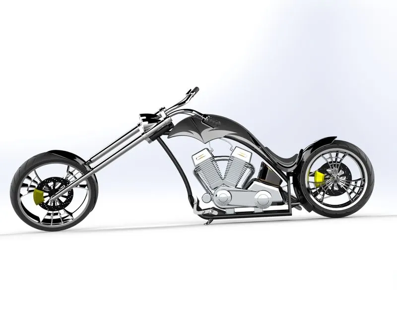
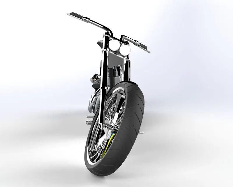
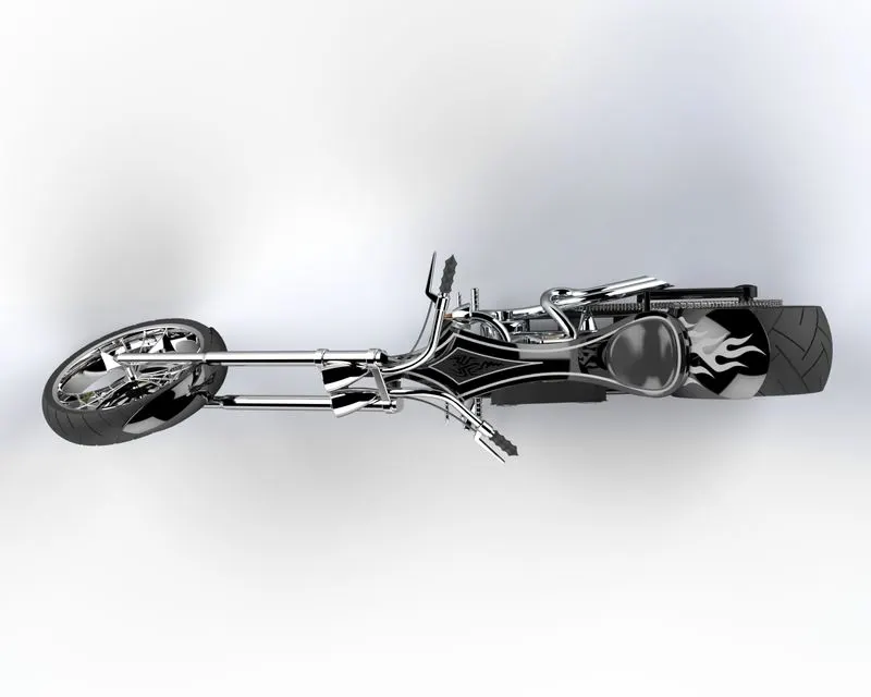
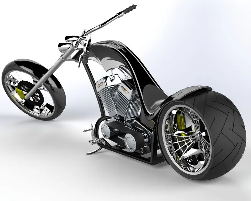
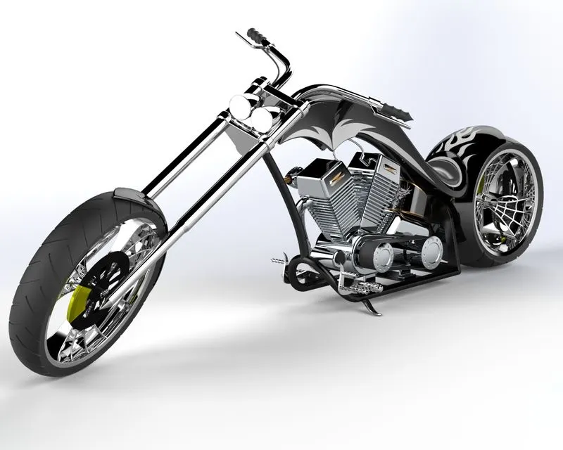
Rendered images of Chopper in different environments