Advanced Sheet Metal Design Using NX Cad Challenge_7_ Metal bracket-II
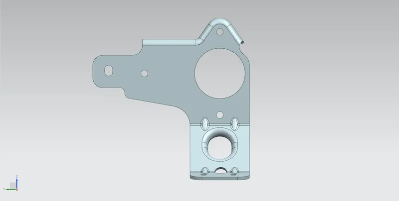
Modelling of a Sheet Metal Bracket.
Objective
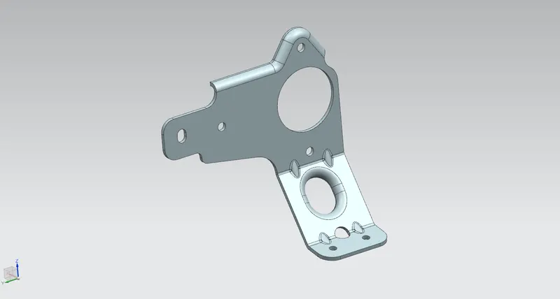
To Design a sheet metal bracket from a given 2D drawing.
Introduction
Our main aim is to design a sheet metal bracket using, various tools and commands in NX cad.
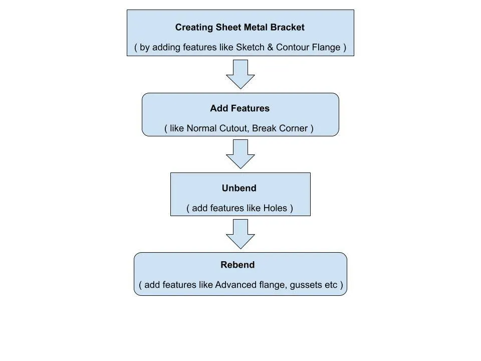
Flowchart
Description
The solid sheet metal bracket is designed by drawing a 2D sketch in a plane and creating flange out of it.
Sheet metal bracket is designed according to the dimensions given in the given 2D drawing.
Even some commands need to be used to obtain the desired Sheet metal bracket.
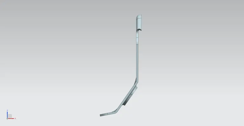
Features used in creating the sheet metal bracket are
Sketch
Contour Flange
Normal Cutout
Break Corner
Unbend
Rebend
Advanced Flange
Hole
Gusset
Sketch
Creates a 2D sketch in the current application. Use the direct sketch tools to add curves, dimensions, constraints, etc.
Contour Flange
Creates a base feature by extruding a sketch along a vector, or adds material by sweeping a sketch along an edge or chain of edges.
Normal Cutout
Normal Cutout is used to cut material by projecting a sketch into the model & then cutting perpendicular to the faces intersected by the projection.
Break Corner
Break corner command rounds or chamfers a sharp corner of a tab or flange.
Unbend
Unbend flattens a bend and the material adjacent to the bend.
Rebend
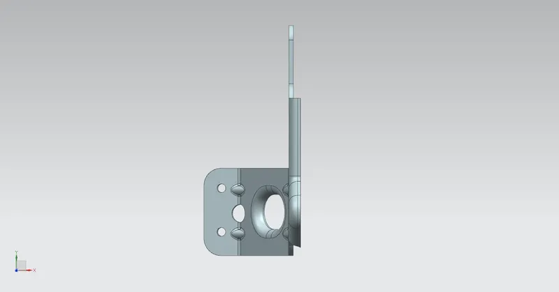
Restores an unbend feature to its previous bent state, along with any features added after the unbend feature.
Advanced Flange
Adds a flange along an edge using a bend angle or a reference face. The edge and reference face can be curved.
Hole
Adds a hole to one or more solid bodies in a part or assembly with options for counterbored, countersunk, and threaded.
Gusset
The gusset is a Stiffening feature, this command used to strengthen the designed sheet metal part.
Conclusion
Sheet metal bracket is designed using NX Cad from the given 2D drawing.