Advanced Sheet Metal Design Using NX Cad Challenge_7_ Metal bracket-II
Metal Bracket-II Design using Sheet metal in NX Cad
Objective:
In this tutorial we will learn the step by step procedure to create "Metal Bracket" from the given 2D Drawing.
Introduction:
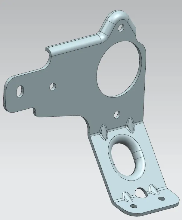
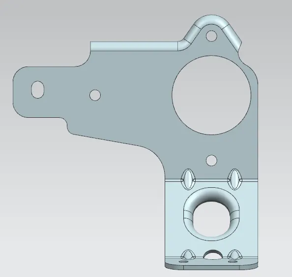
A Metal Bracket of 3mm thickness with complex shapes and cuts in it.
Design Methodology:
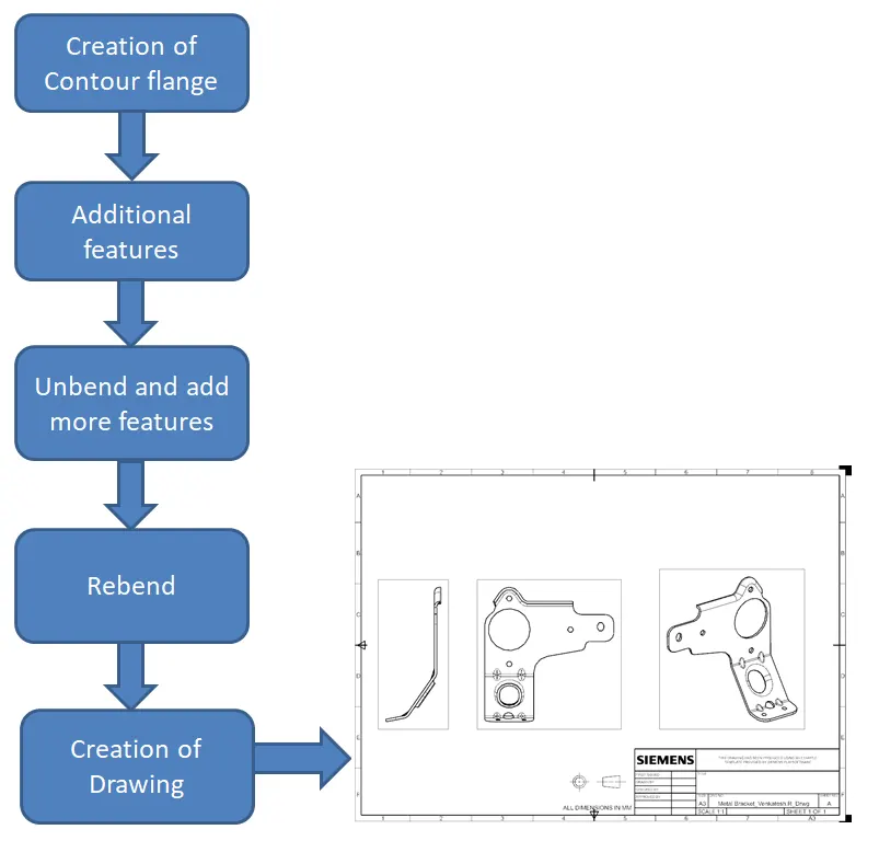
Description:
1. Select the right plane YZ and sketch a profile as shown in the image.
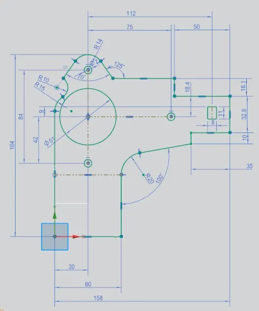
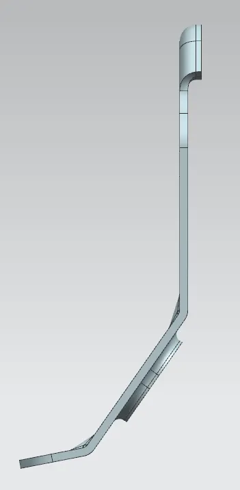
2. Select the front plane XZ and sketch the flange upto 164mm in length with 2 bendings at different angles.
3. Click on the Contour flange option and select the second sketch with 3mm thickness and 158mm length.
4. After this, do the normal cut for the sketch 1. And remove the excess material except the profile.
5. Provide Break corners to required corners with possible radius.
6. Unbend the flange and give some additional features as needed, like hole, slots, etc.,
7. Rebend the flange and create an advanced flange 5mm long and 90 degree angle.
8. Then give 5mm round gussets of 4 nos. at the two flanges on tab.
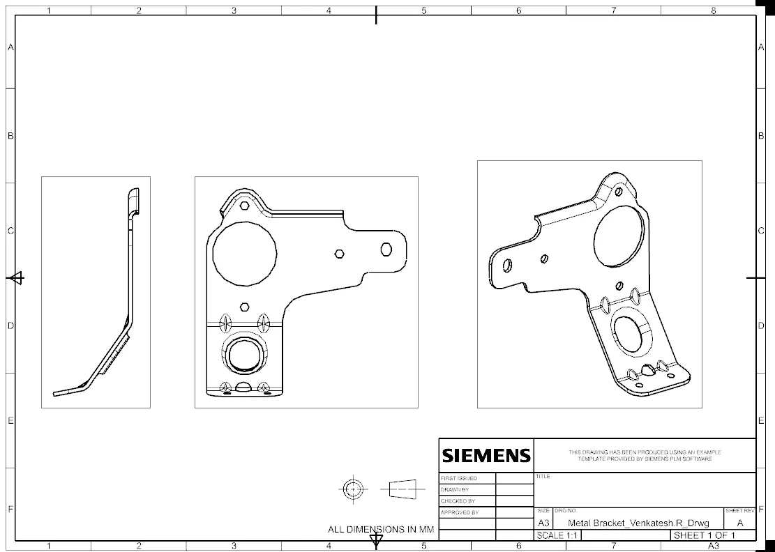
9. Save the part and create a drawing with possible views to show all the information about the part creation.
10. Save the drawing as per the part name.
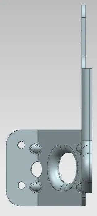
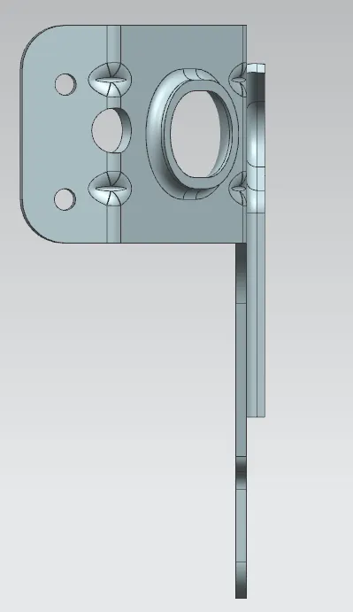
Here are the few images of part and drawing of the Metal bracket,
Conclusion:
Thus the metal bracket with complex design and advanced flanges are created using the NX Cad software.
Hope it is useful for you guys.