Advanced Sheet Metal Design Using NX Cad Challenge_7_ Metal bracket-II
MODELLING OF SHEET METAL BRACKET-2
OBJECTIVE
Modelling a Sheet Metal Bracket using NX CAD. Write a detailed report on Sheet Metal Component with good explanation on Sheet Metal modelling tools applied throughout the modelling. Also attach the Final model Images of Sheet Metal Bracket.
INTRODUCTION
Sheet metal is metal formed by an industrial process into thin, flat pieces. Sheet metal is one of the fundamental forms used in metalworking, and it can be cut and bent into a variety of shapes.
Siemens NX CAD software is a flexible and powerful integrated solution in sheet metal modelling that can helps us to deliver better products faster and more efficiently. NX delivers the next generation of design, simulation, and manufacturing.
Metal Bracket is a device that projects from or overhangs a wall to carry a weight. It may also serve as a ledge to support a statue, the spring of an arch, a beam, or a shelf. The metal brackets are manufactured by conducting stamping or die casting operation.
DESIGN METHODOLOGY
DATA FROM 2D SKETCH

COUNTOUR FLANGE IS CREATED FOR THE SKETCH
NORMAL CUTOUT IS USED TO ACHIEVE THE DECIDED SHAPE
BREAK CORNER IS USED TO ACHIEVE A SMOOTH EDGE
UNBEND IS PERFORMED FOR THE MODEL
HOLES ARE CREATED ON TOP OF THE SURFACE
REBEND COMMEND IS USED
ADVANCED FLANGE IS CREATED
A HOLE IS CREATED AND AN ADVANCED FLANGE COMMAND USED
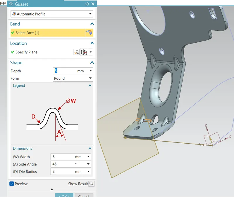
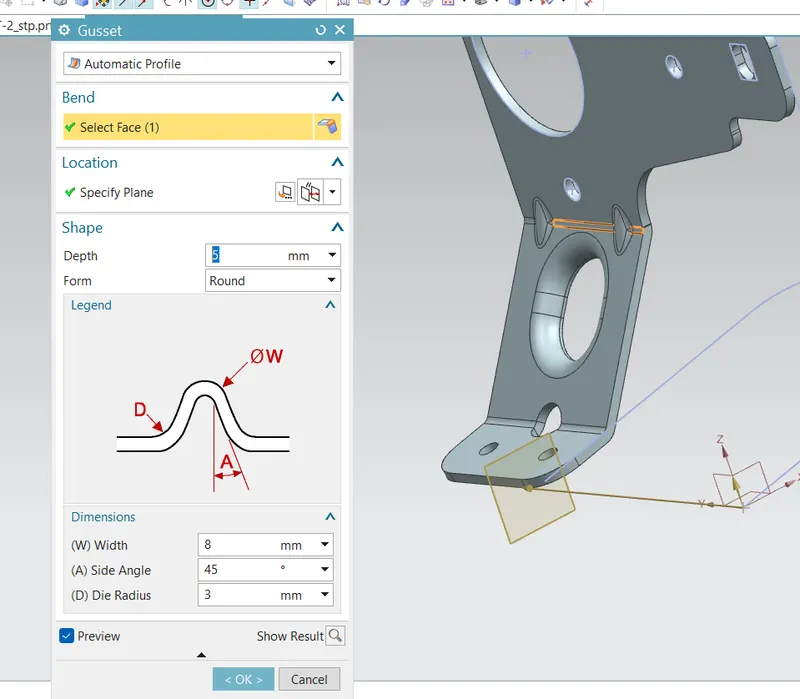
GUSSET IS ON BEND TO INCREASE THE STRENGTH
FINALLY 2D SKETCH IS CREATED
Description
Open Siemens NX CAD
Create a New Sheet Metal Model with respective Folder
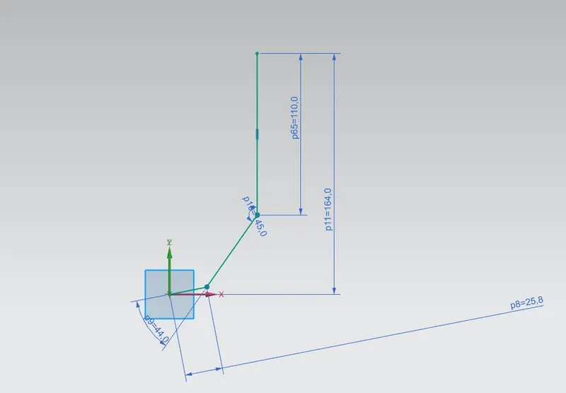
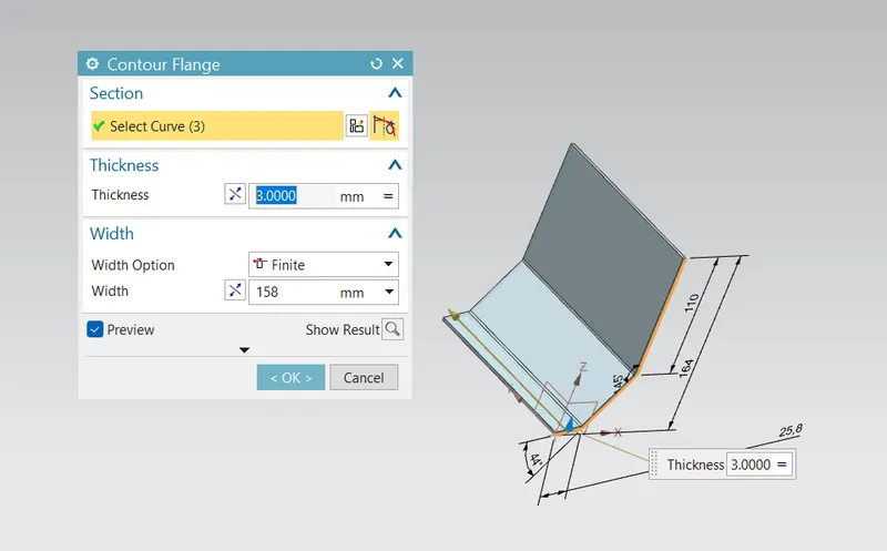
Then Start a new Sketch and then create a Countour Flange Along it.
- Contour flange is available when an unconsumed open profile exists in your part. A contour flange is defined using a profile sketch and a straight edge on an existing face. The profile sketch consists of lines, arcs, splines, and elliptical arcs.
Then Create another Sketch And then Normal cutout
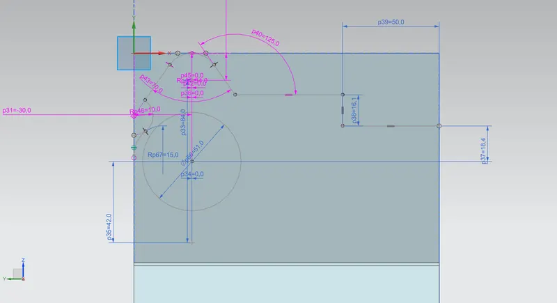
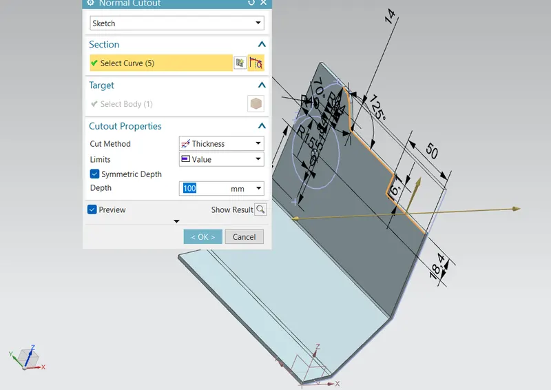
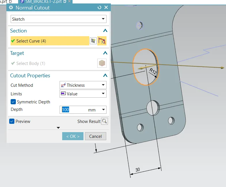
Normal Cutout:- It is used to cut or create a gap in the sketch.
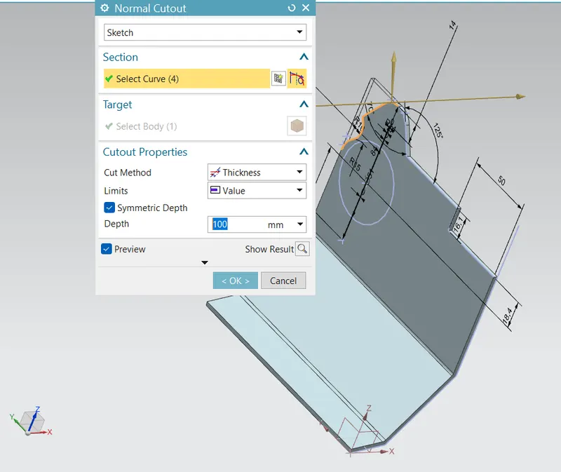
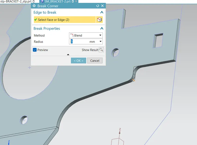
Then Use Break Corner
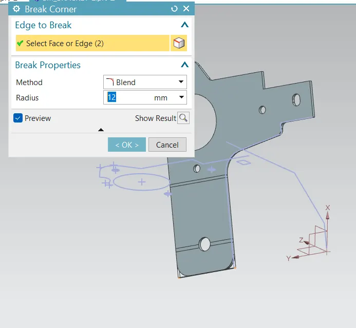
Break Corner:- It is used to make the comers blend with some self dimensioned radius in order to make corners smooth.
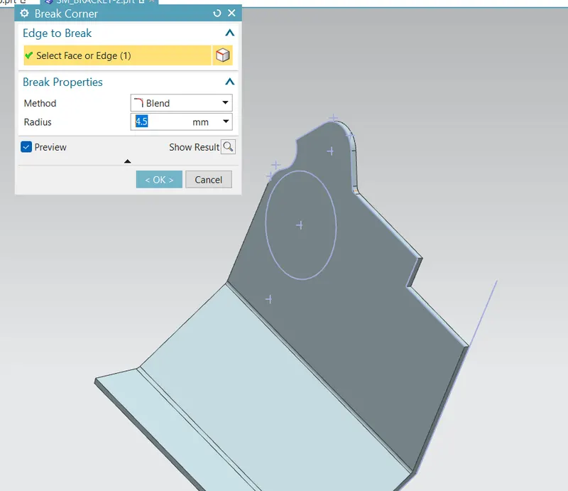
Then unbend
As the tool name indicates the bend tool is used to bend the sheet metal bodies and the unbend is viceversa of the bend tool,It is to unbend the bent regions.
The part is unbend to create additional features such as hole, dimple, beads which otherwise cannot be created if it not unbend. Moreover it also helps to check whether the part is a sheet metal or not. If the part is unbending then it is a sheet metal otherwise it is still a solid body or dumb body.
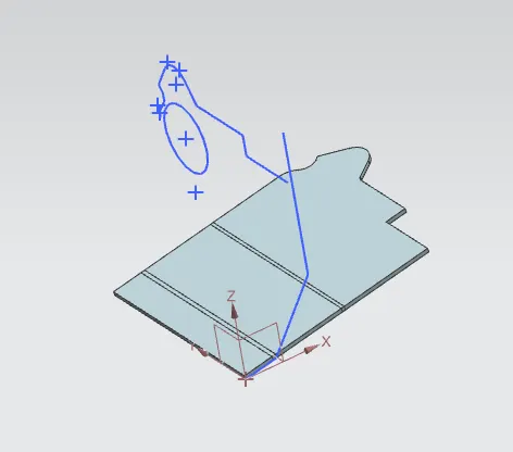
Then Sketch and Normal Cutout
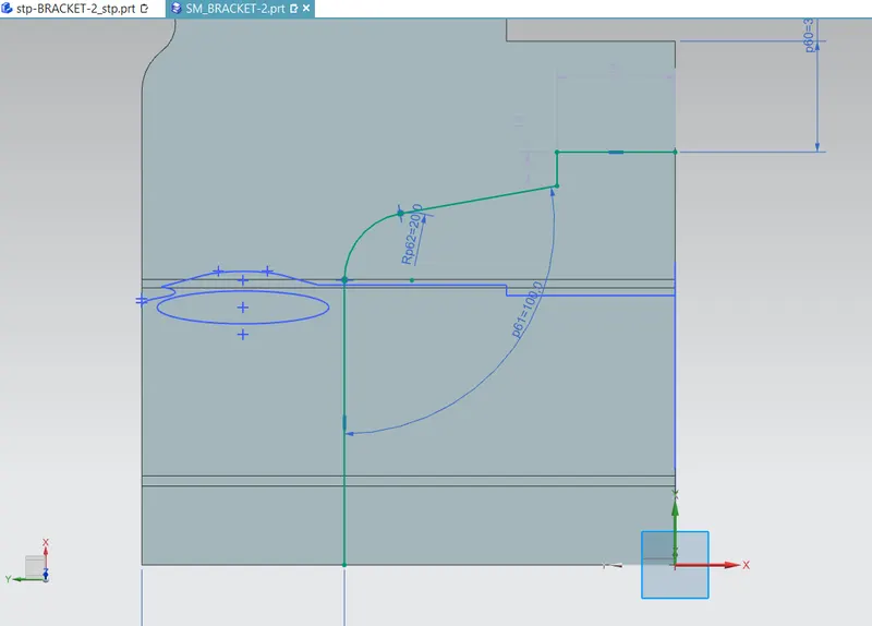
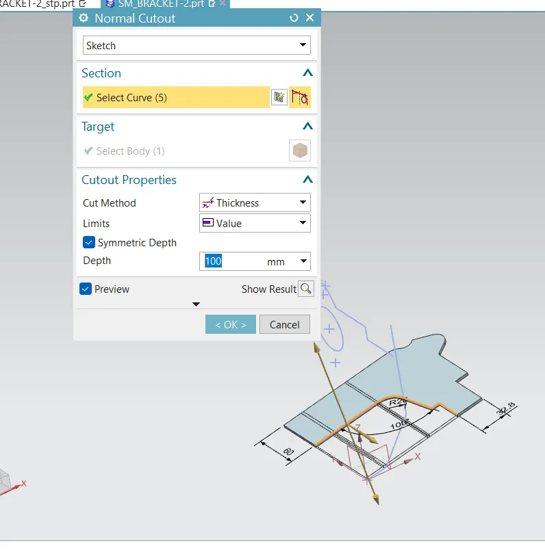
Then Add another sketch And then remove materials using Normal Sketch. Then Add break Corners
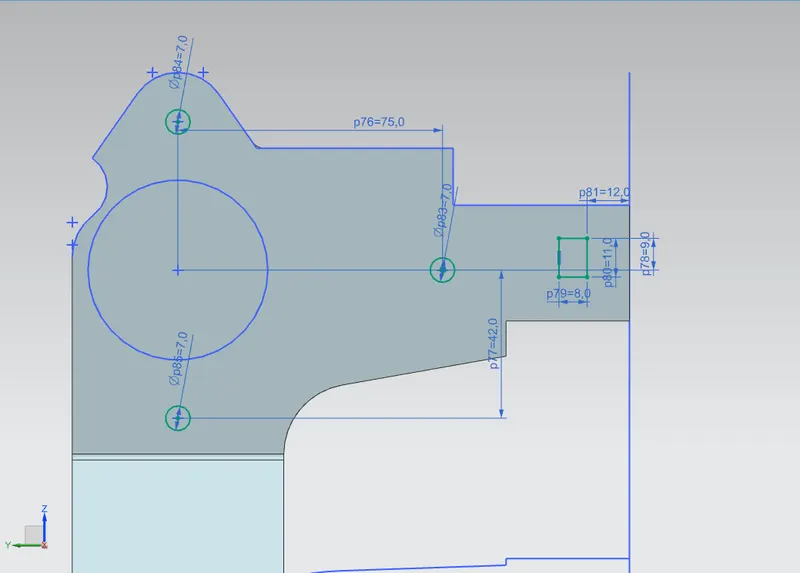
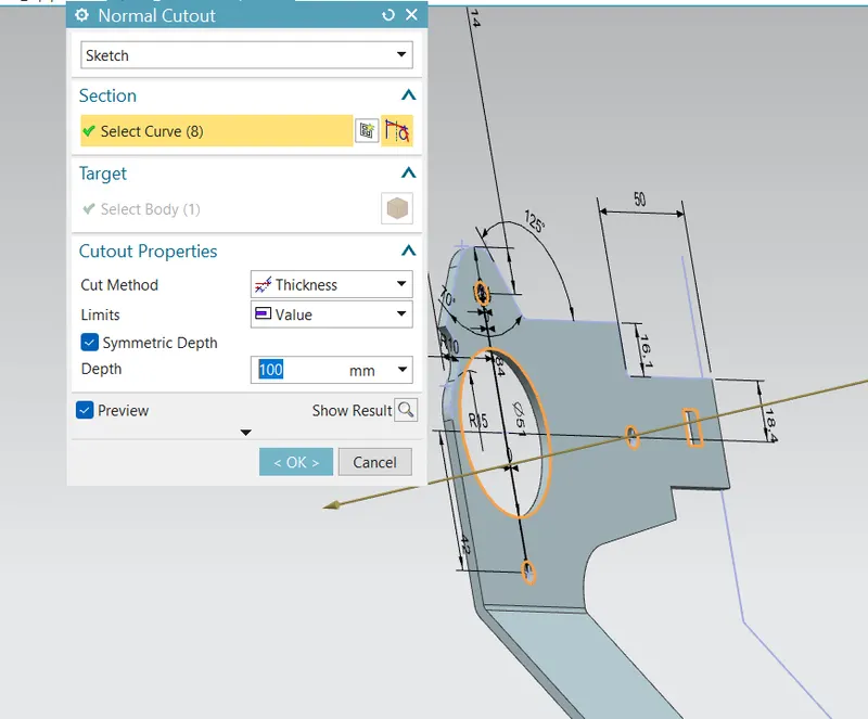
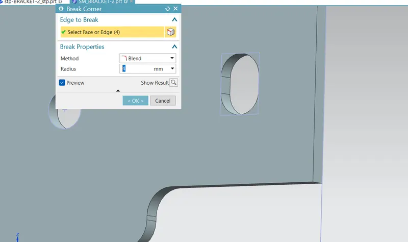
Then Another Sketch and then Normal cutout
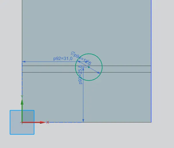
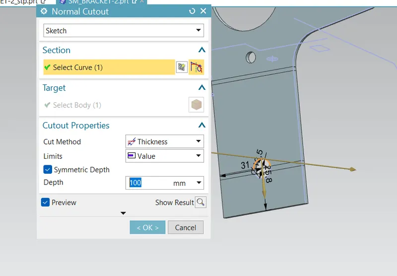
Add Break corners
Then add Flange using Advance Flange.
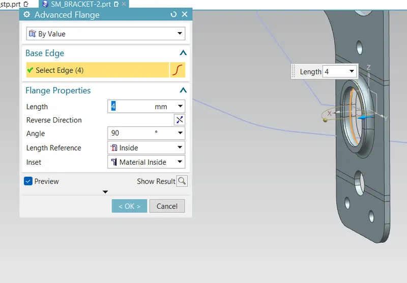
- Advanced flange is used to create flange along an edge or reference face that can be curved. This feature also allows the user to create flange along connected chain of edges. Advanced flange can be created by using reference plane as shown.
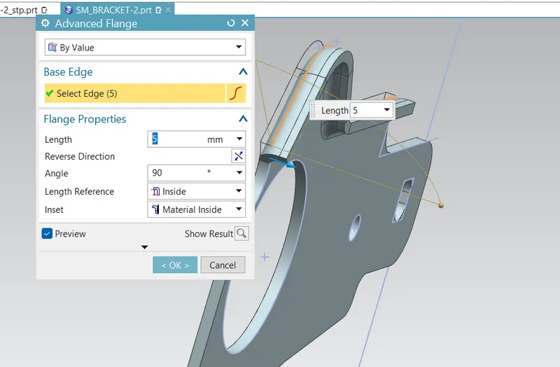
Then Create Hole
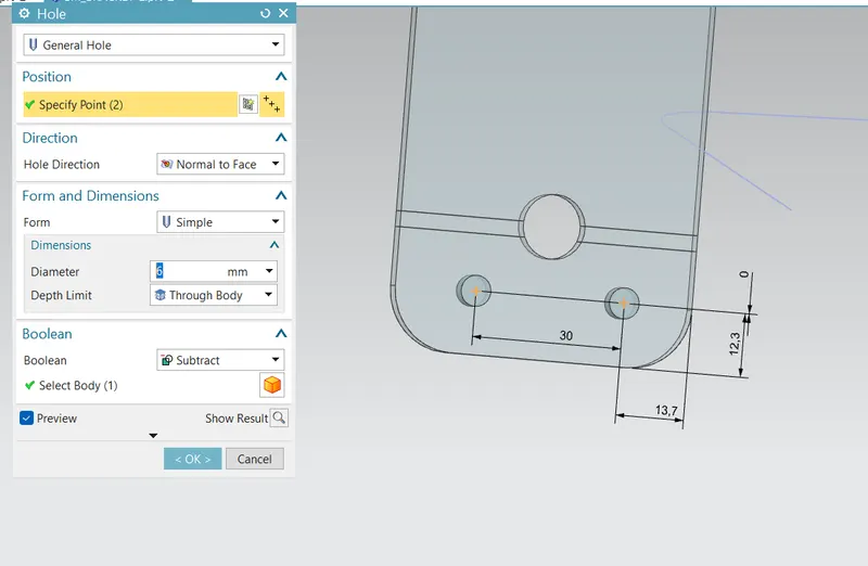
Another Normal Cutout and Advance Flange
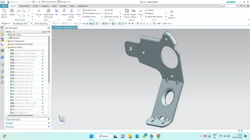
Then Add Gusset to enhance the strength of the metal bracket
-
A gusset is of round and square that is used to transfer tensile stresses from the beam to the column and aid the connection of two members.
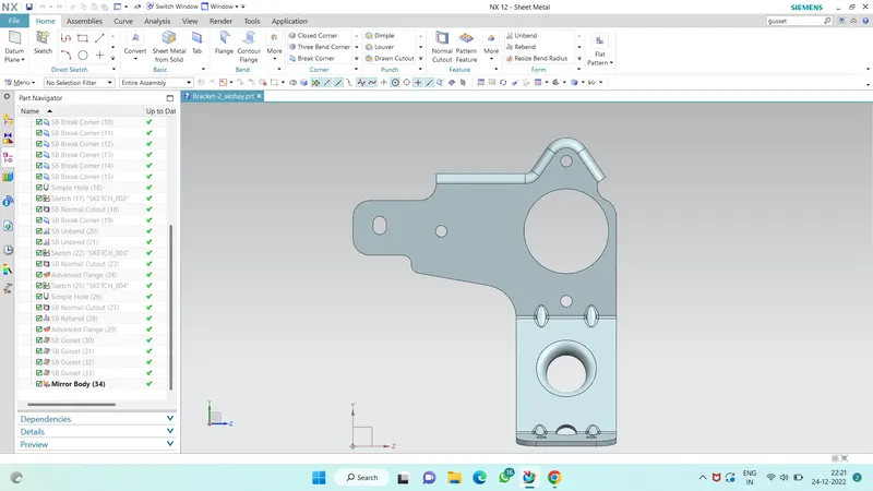
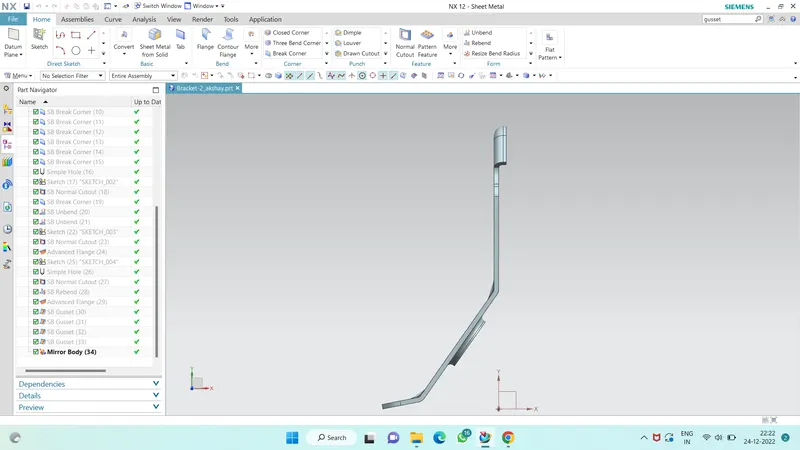
Part Views :
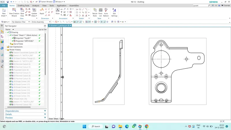
Drawing Sheet :
CONCLUSION:
The sheet metal bracket is designed and created successfully using the NX CAD SOFTWARE. From this project, we get to understand advanced flange and gusset features while working on it.