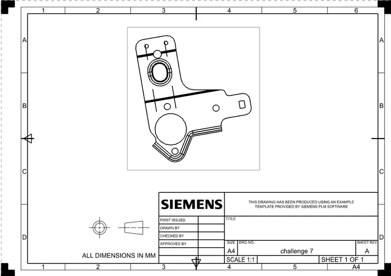
Advanced Sheet Metal Design Using NX Cad Challenge_7_ Metal bracket-II
OBJECTIVE
The aim of this project to design a metal bracket and create a detailed drawing for manufacture using Siemens NXsheet metal Application
INTRODUCTION:
Sheet Metal Fobrication is the process of forming parts from a metal sheet by punching,cutting, stamping, and bending 3D CAD fles are converted into machine code, which controls a machine to precisely cut and form the sheots Into the final part. Sheet metal parts are known for their durability, which makes them great for end use applications (eg chassis).
Parts used for low volume prototypes, and high voiume production runs are most cost effective due to large initial setup and material costs. Because parts are formed from a single sheet of metal, designs must maintain a uniform thickness. Hence the designer must be sure to follow the design requirements and tolerances to ensure parts fall closer to design intent and cutting sheetsof metal.
Critical Dimensions The following are some terminology that are used in sheet metal. Designers need to adhere to machinery guidelines when designing for bending. Bends can be defined by these parameters. Some critical dimensions thatneed to be considered when setting up sheet metal design in CAD software are sheet metal thickness, the k-factor and bend radius. One needs to check that these factors are consistent with the tooling that will be used in manufacturing
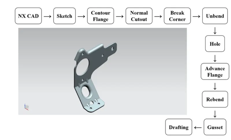
DESINGN METHODOLOGY:
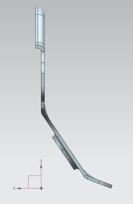
DIFFERENT VIEW
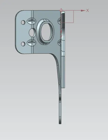
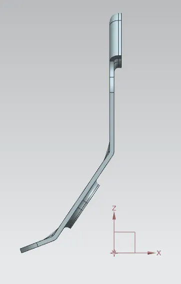
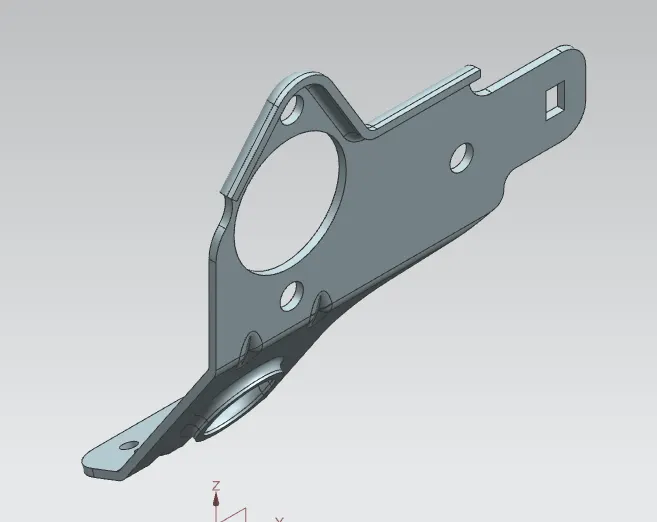
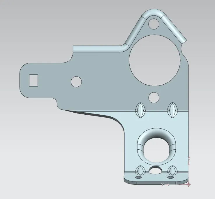
DRFAT VIEW