Advanced Sheet Metal Design Using NX Cad Challenge_7_ Metal bracket-II
AIM - DESIGN OF SHEET METAL BRACKET 2
OBJECTIVE -creation of the metal bracket 2 from 2d sketch to 3d model using nx software.
INTRODUCTION-
Sheet metal is metal formed by an industrial process into thin, flat pieces. Sheet metal is one of the fundamental forms used in metal working and it can be cut and bent into a variety of shapes. Countless everyday objects are fabricated from sheet metal. Thicknesses can vary significantly; extremely thin sheets are considered ffoil or leaf and pieces thicker than 6 mm (0.25 in) are considered plate steel or "structural steel"
NX most widely used computer aided designing software for designing in automotive ,engineering & manufacturing industries.
DESIGN METHODOLOGY
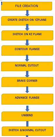
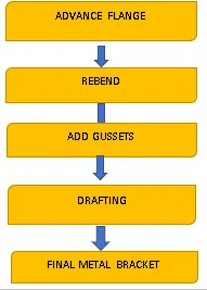
TOOLS USED FOR DESIGNING OF SHEET METAL BRACKET 2
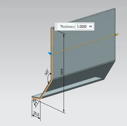
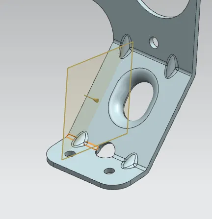
CONTOUR FLANGE : This tool is used to make the flange of connected curves which are in angle direction.as shown in picture.by giving the sketch as input.
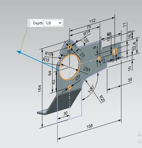
NORMAL CUT OUT: this tool cuts the unnecessary sheet to get the desired shape which we required by taking the curve as input feature
BREAK CORNER: this tool make the sharpe edges as rounded as same like fillet by giving the radius value as input.
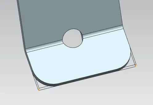
UNBEND:
TO add some additional features like holes,beads,dimples etc, it is impossible to add when the sheet is is some shape & if we add also we dont get the accurate shape so that the sheet is to make flatten. this is the tool whick make thesheet as flat surface by selecting the stastionaly face & complete sheet as inpuut.
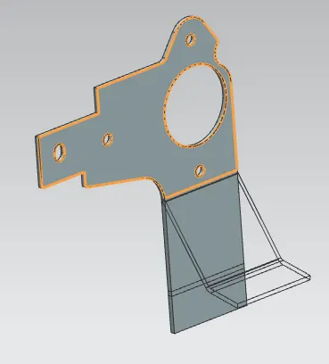
ADVANCE FLANGE: This is the very special tool in the nx which is satisfying one. because it creates the flange at tipical areas like curve ,& angles edges as input where it is impossible with normal flange command.easy to create round corners flange with is tool.
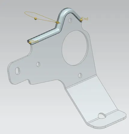
REBEND; This too is used to make the unbend sheet metal to regain its original shape.after adiing the additional features.
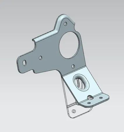
GUSSETS: This feature is like beads commands to add strength to the sheet metal parts uses mostly in the corners of the sheet & in angles shape corners.
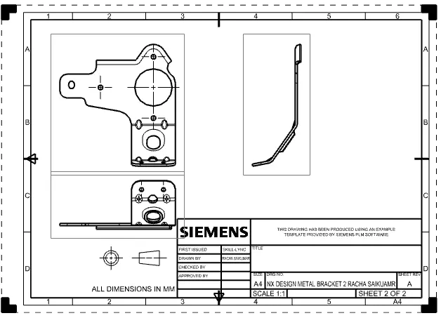
DRAWING SHEET(drafting): This drawing sheet is a predefined assumption sketch were be assumed how the design model to be in 3d view it consists all the required dimensions.
DESIGN PROCEDURE OF SHEET METAL BRACKET 2
- Create sketch on the yz plane with referance from the drawing sheet as given input.
- create another sketch on the xz plane
- create contour flange with the second drawn sketch as curve as length of 158.& 3mm thicknesss.
- with the help of the first drawn sketch make the cutout of the shape required on the contour flange sheet metal.
- make brake corners on the required corners of 4.5mm radius.
- unbend the sheet metal to add some additional fweatures on it.
- create the sketch of circle at desired space & make normal cutout
- add fillets with brake corner tool. & rebend it
- Add advance flange on the edge selecting as required one.of 3m radius & 5mm length.
- unbend the sheet metal bracket.
- create holes & cutout on the sheet
- Add advance flange at the cutout feature of 4mm length & 3mm radius.
- rebend the sheet metal.
- Add the gussets on the sheet metal by select the required bend as input & give the dimensions % direction.
- thus the required bracket is ontained as final.
ISOMETRIC VIEW
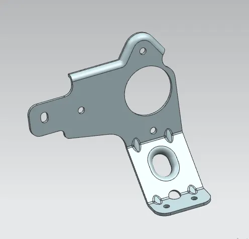
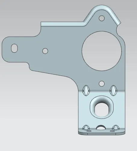
TOP VIEW
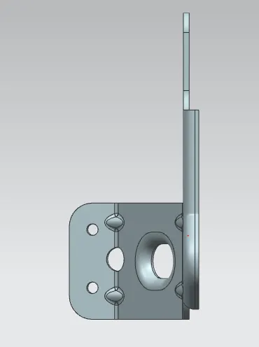
FRONT VIEW
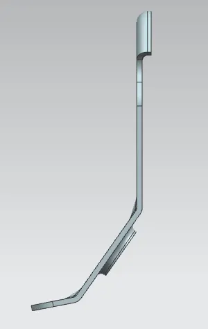
SIDE VIEW
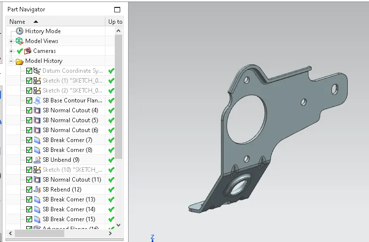
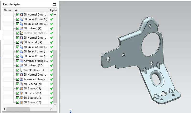
FEATURE TREE
DRAFTING
CONCLUSION- MODELING OF SHEET METAL BRACKET 2 IS DONE & RELAVENT IMAGES & FILES ARE ATTACHED IN THE ANSWER BOX.