Advanced Sheet Metal Design Using NX Cad Challenge_7_ Metal bracket-II
SHEET METAL BRACKET
OBJECTIVE
To design a sheet metal bracket and carryout drafting using Siemens NX.
INTRODUCTION
- NX, formerly known as “unigraphics”, is an advanced high-end CAD/CAM/CAE, which has been owned since 2007 by Siemens PLM Software.
- Sheet Metal Fabrication is the process of forming parts from a metal sheet by punching, cutting, stamping, and bending.
- The thickness of sheet metal starts from 5 mmand goes up to 6 mm. Anything above that is a metal plate. The thin sheet metal is easy to form, while still providing great strength.
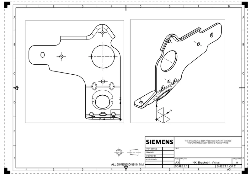
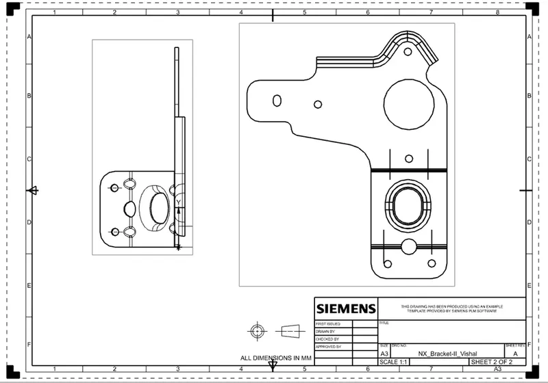
- Drafting is one of the application in NX Sheet Metal used to get 2-D drawings of all the different views of the designed model.
DESIGN METHODOLOGY

DESCRIPTION
- Contour Flange - It is used to extrude a sheet metal surface upto certain distance with a thickness, taking any sketch as reference.
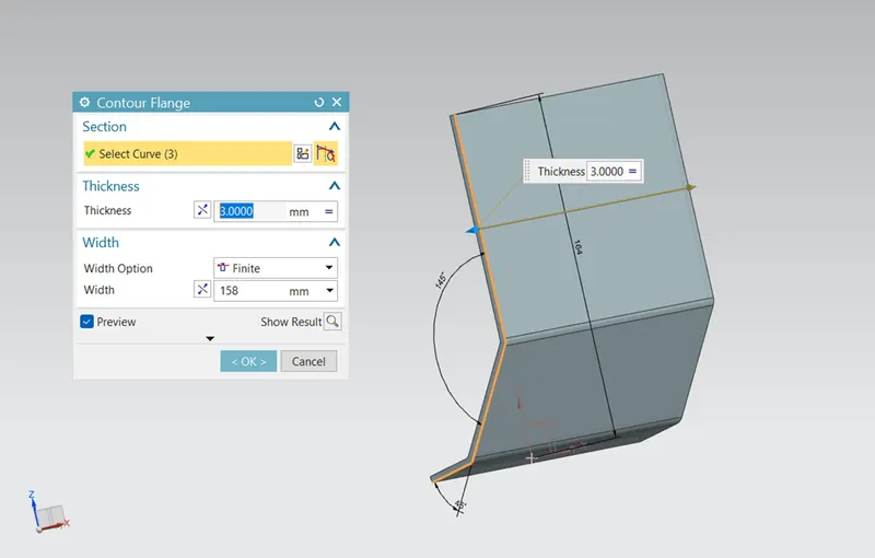
- Normal Cutout – This feature is used to make a cutout on the sheet metal part giving appropriate thickness using a sketch.
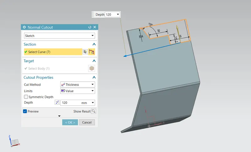
- Break Corner - This feature is used to create a chamfer at the sharp edges in the sheet metal model.
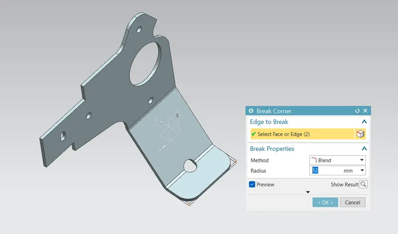
- Unbend – It is used to unbend the previously bended regions.
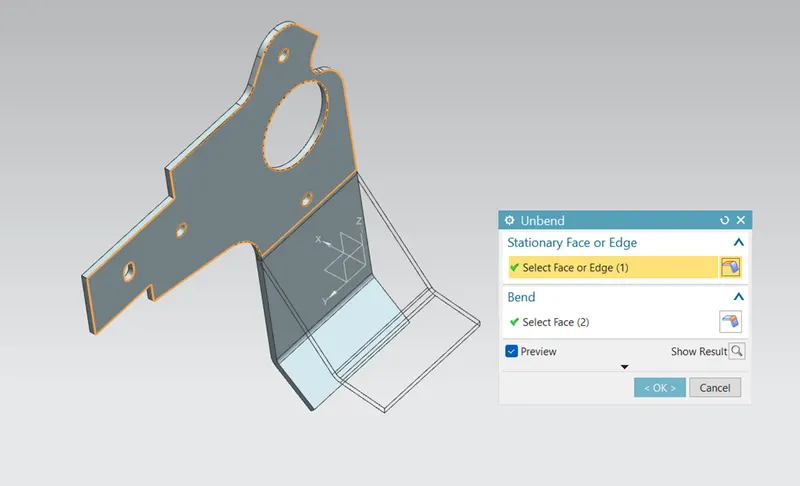
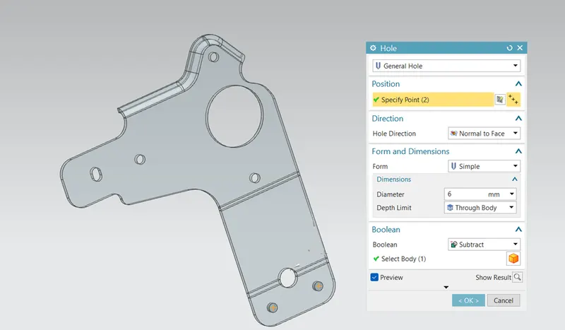
- Simple Hole - By drawing points on the sheet metal, taking those points as reference holes are created.
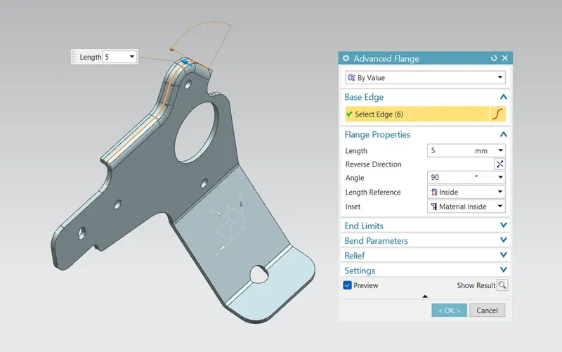
- Advance Flange – Flange is created using any edge as a reference. Variable length and angle flanges can be created. Advance flange gives smooth finish at the edge where flange begins.
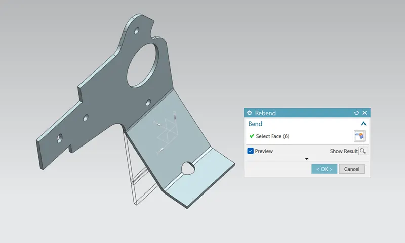
- Rebend - This feature is to rebend the unbent model. This is done by selecting all the bends.
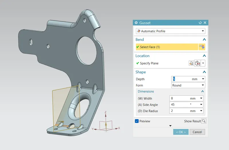
- Gusset – Gussets are used to strengthen a flange without the need for secondary processes such as welding.
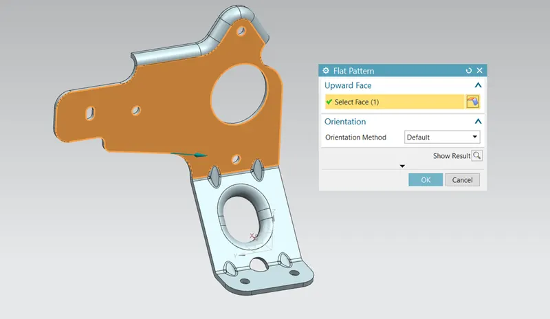
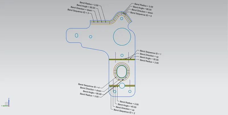
- Flat Pattern - This feature is used to obtain a 2D projection of the flat sheet metal.
VIEWS OF THE MODEL
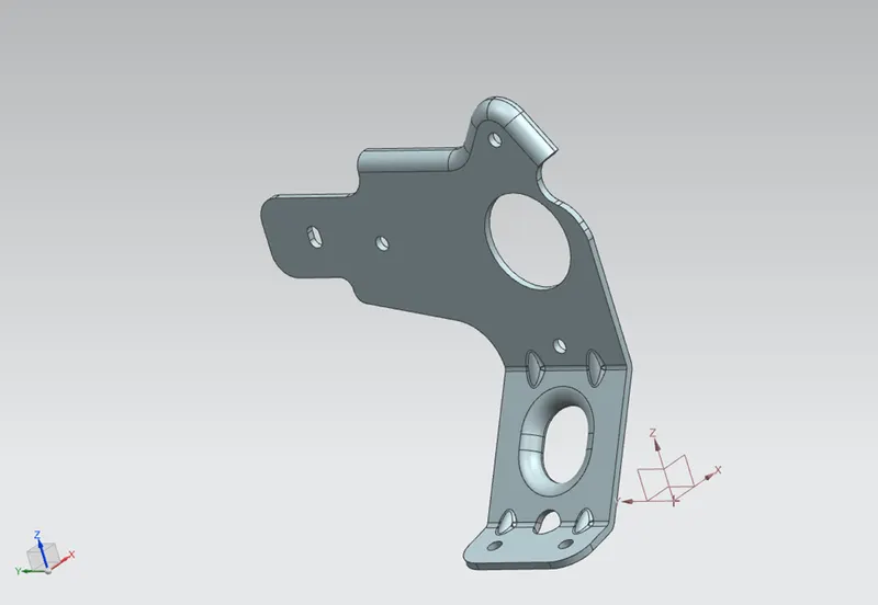
- Isometric view
- Front view
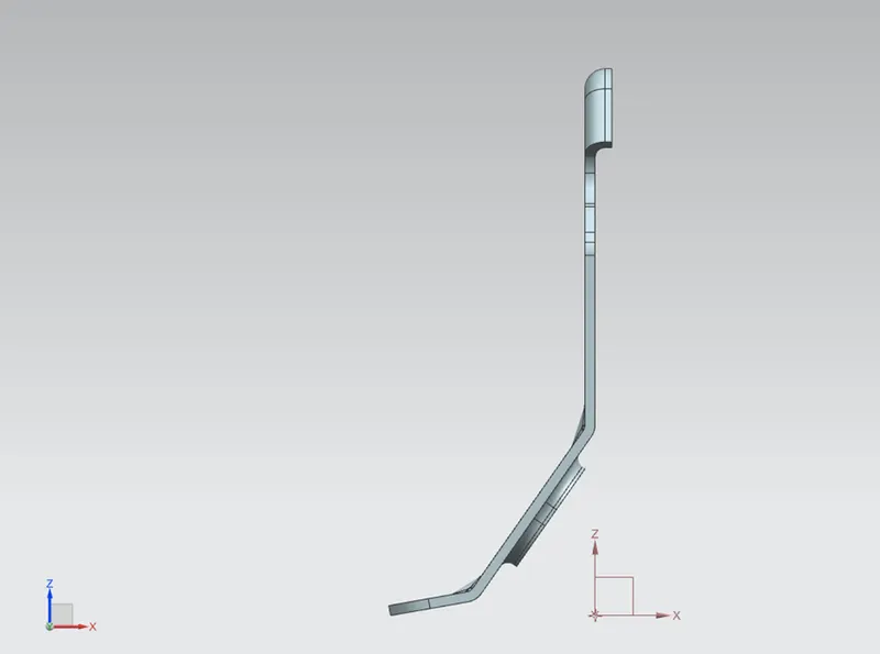
- Side view
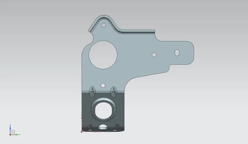
- Top view
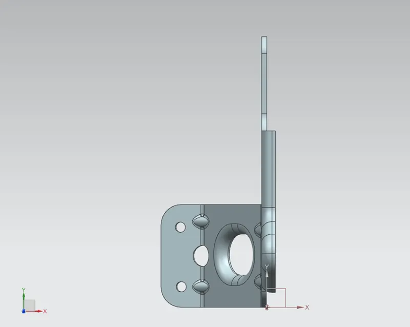
- A view of model
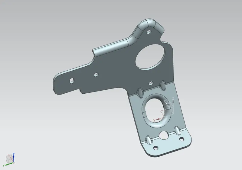
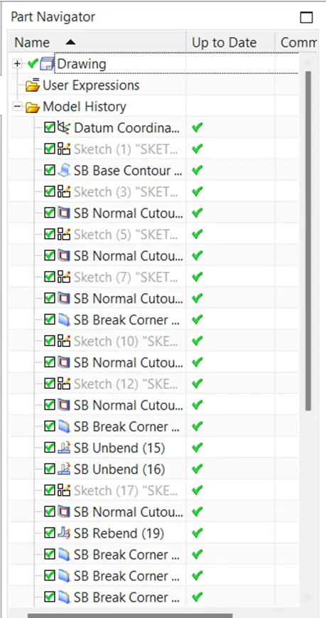
FEATURE TREE

DRAWING SHEET
CONCLUSION
- Sheet metal bracket in NX CAD is created by using the given sketches and procedures.
- Flat pattern of the model is obtained and drafting is done.