Advanced Sheet Metal Design Using NX Cad Challenge_7_ Metal bracket-II
Modelling of Metal Bracket in Siemens PLM NX 12
By
Santhoshsivan.G
Introduction
In this model, we learn how to create metal bracket model on siemens PLM NX 12 by using some tools like datum, normal Cut-out, Bend, unbend, contour flange, etc.
This are the following tools use to create casing model.
- Datum
- Unbend
- Contour Flange
- Break corner
- Rebend
- Hole
- Normal cut-out
- Advance Flange
- Gusset
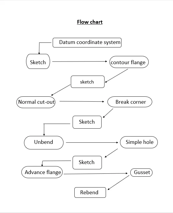
Step by step procedure to creating this model as shown in flowchart.
1.Datum coordinate system:
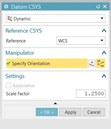
Datum coordinate system is the base plane for creating the components, which means the objects are created relative to some aspects, such as point, plane or axis. In this system have three categories. They are,
- Machine coordinate system
- Absolute coordinate system
- Work coordinate system
In machine coordinate system mainly used for CAM. CAM stands for computer aided manufacturing which means it’s used in this sectors CNC, VMC, etc.
In absolute coordinate system means to define a parametric location for an object such as point, or centre of an arc. In absolute coordinate system does not change or move. It provides a fixed point in space from which to begin modelling
In work coordinate system means the object is still used to determine the orientation and the origin. In WCS is moved nothing else go with it.
2.Ubend:
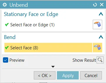
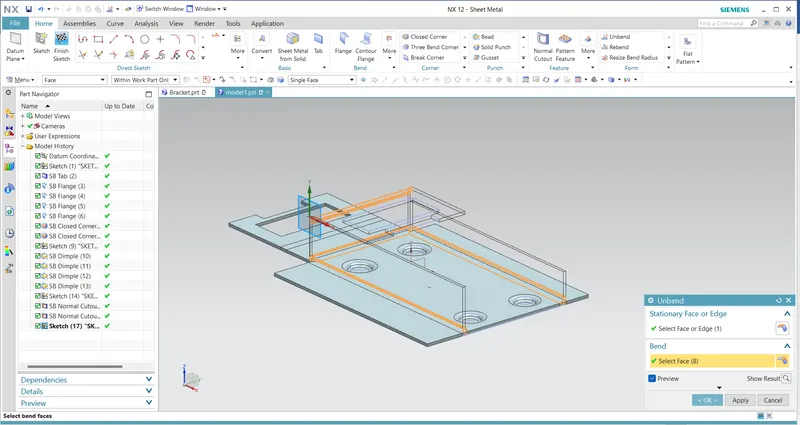
Unbend means to flatten the model of concerned plane of the sheet metal. To select the command by selecting menu-->Insert-->form-->unbend. Select the face on the sketch and drag for select the sketch and click ok.
3.Contour Flange:
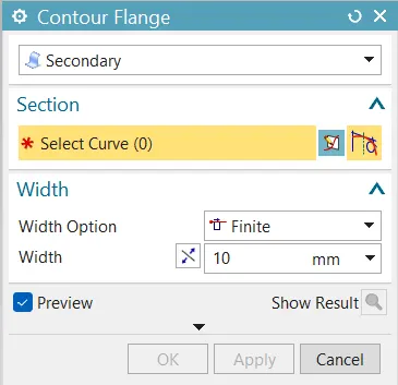
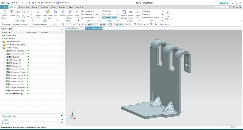
Contour flange means to create a flange by extruding a sketch along a vector or by sweeping a sketch along edge or chain of edges select menu-->Insert-->Bend-->Contour flange. NX add bend radius automatically by default.
You can use contour flange as base feature of a new Sheet metal part or contour flange as a secondary flange.
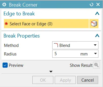
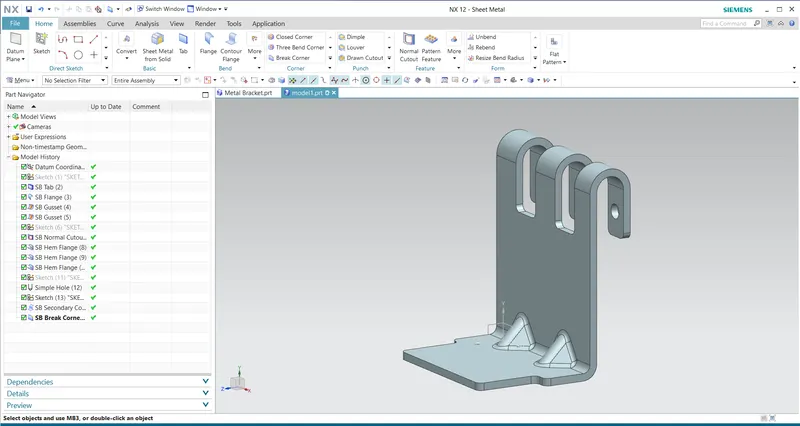
4.Break corner:
Break corner means which use to round or chamfer the sharp corners of a tab or flange (similar to fillet).
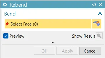
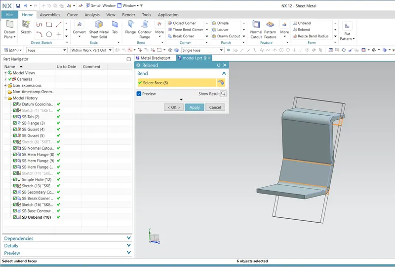
5.Rebend:
Rebend is nothing but to bend the model after unbending. Click the rebend icon and select the faces or simply drag the sketch for selection. After selection click ok.
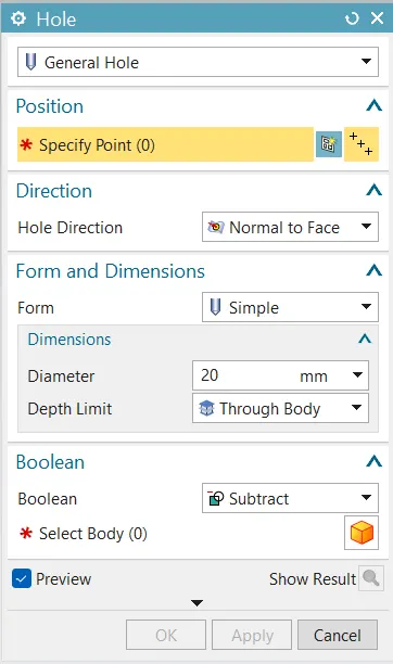
6.Hole:
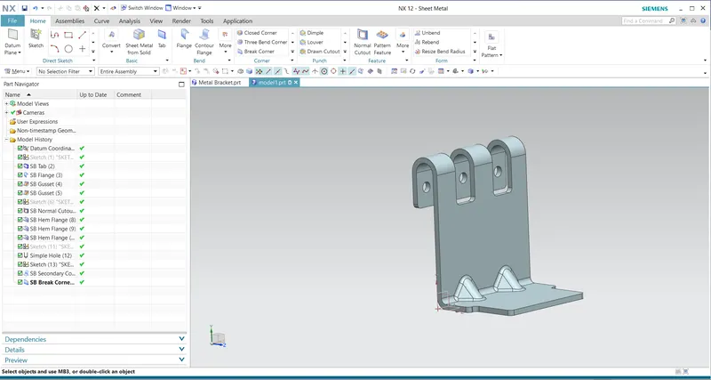
To drill standard-size drill size hole to parts in Siemens NX, you need to click on the Hole command as shown by red arrow above. After entering to the Hole command in Siemens NX, you need to select the Drill Size in property manager and click ok.
7.Normal cut -out:
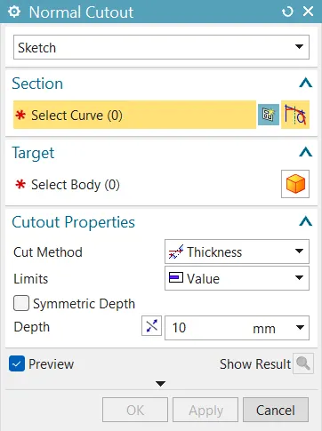
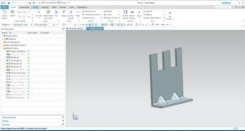
Normal cut-out means to cut material by projecting a sketch in to model and then cutting perpendicular to the face intersect by projection. Use planar sketch or 3D curves to specify the section for normal cut-out.
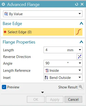
8.Advance flange:
This command to add a flange along an edge using a bend angle or a reference face. The edge and the reference face can be curved. You can also select a single edge or a chain of tangent edge.
9.Gusset:
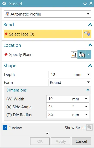
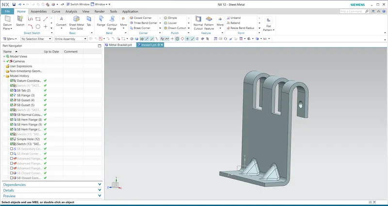
The gusset means to strengthening the bracket by an angle of a structure. To create the gusset by select the bend and the face of the sketch then give the distance for applying gusset. The select the shape and give required value in the gusset property manager. Then click ok.
Modelling of Metal Bracket:
By modelling the metal bracket, they are some commands are used for complete the metal bracket model. Flow chart shows the process and how to create this in step by step
First select the sketch and create it. After creating the sketch select the counter flange option and give the required values in the property manager. Then click ok.
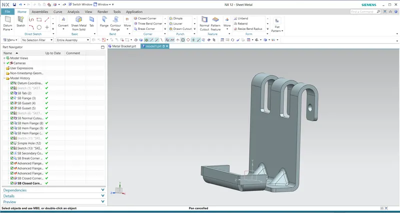
Use unbend option for creating holes, normal cut-out and advance flange by selecting unbend option. Select the face and drag the entire sketch for unbend.
Draw three horizontal, two vertical lines and curve as per the requirement for normal cut-out. Click normal cut-out option and select the lines, after that select cut method and depth in the property manager and click ok. Again, draw some horizontal lines and vertical line after creating the sketch click normal cut-out and give required value and click ok. After that create the circle for creating hole. Then draw two rectangles in the plane and give required dimensions and click finish.
Use normal cut out option to remove the material from the bracket. Most important thing is removing any sharp edges in our model by using break corner command option. In break corner property manager select plane and select all corners by dragging, give radius value and click ok.
After that use advance flange option for creating the flange. Note click single curve instead of tangent curve option for creating flange.
Then use gusset option for creating gusset in the tab. Click gusset and select the bend for creating then select the face and give required distance. After that select gusset type and values (depth, width, angle, etc) in the property manager. And click ok.
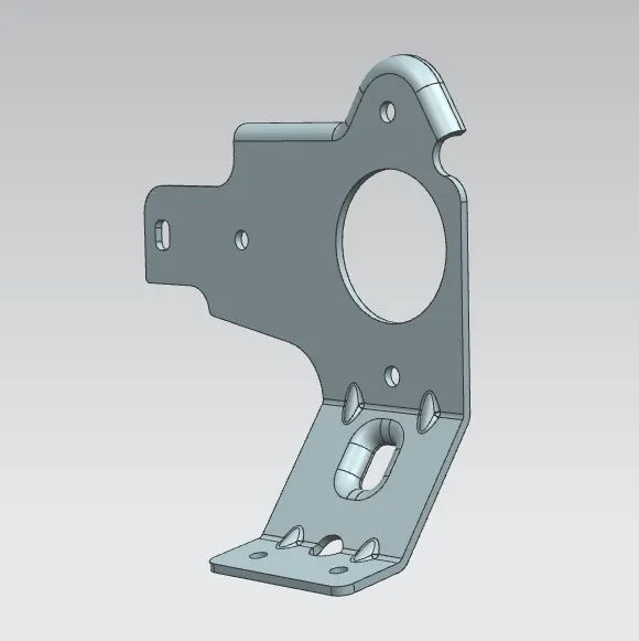
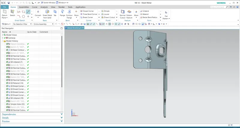
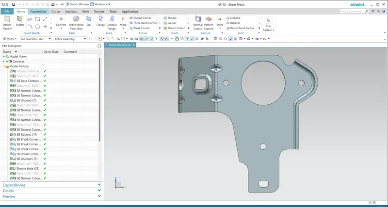
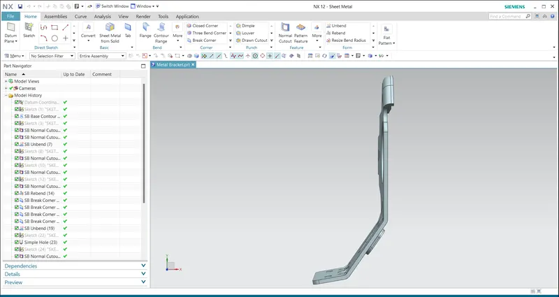
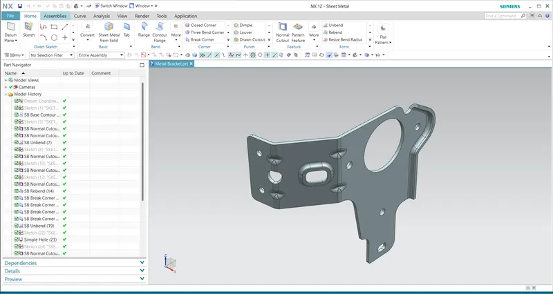
Finally save the create model in concurrent folder. Metal bracket model as shown below.
Metal Bracket Model:
Conclusion:
The modelling of metal bracket as completed in PLM NX12. While creating the bracket, understood the function and uses of the tools.
Metal bracket:
1.Front view:
2.Right side view:
3.Top view:
4.Isometric view:
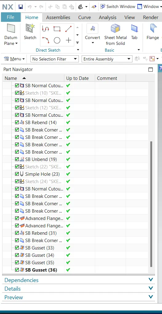
5.History tree 1:
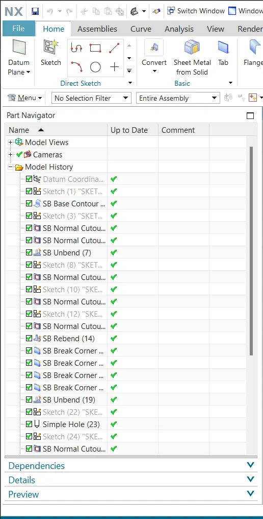
6.History tree 2: