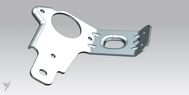
Advanced Sheet Metal Design Using NX Cad Challenge_7_ Metal bracket-II
METAL BRACKET (Using 2D Drawing):
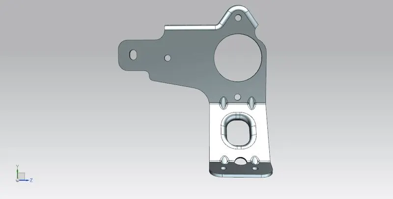
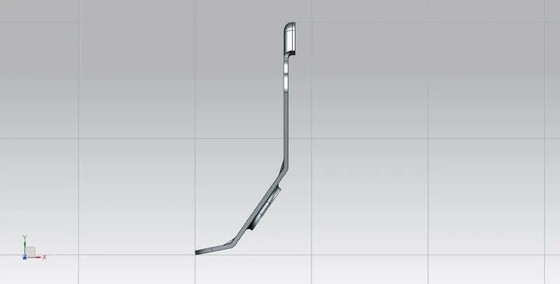
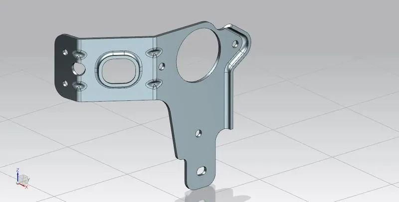
OBJECTIVE: The objective is to create a metal bracket using NX Sheet metal.
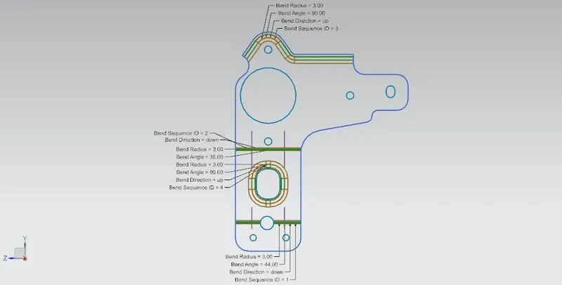
INTRODUCTION: Using a 2D drawing, we will learn how to create a bracket, with contour flange.
FLOW CHART:
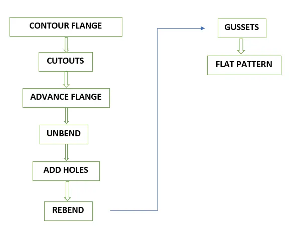
DISCRIPTION:
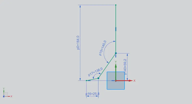
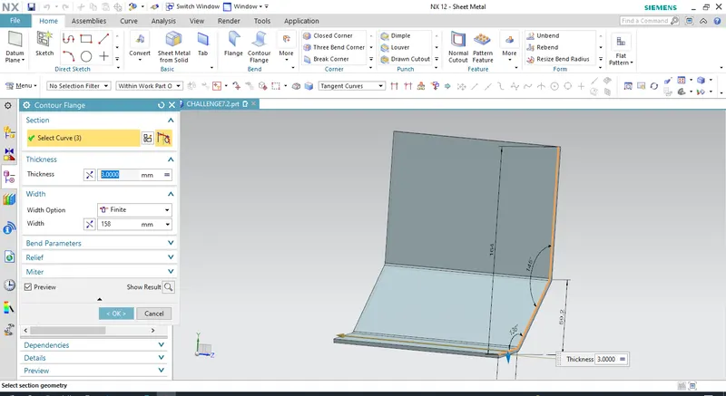
Select a Datum cordinate system for a sketch, and draw the sketch with the required shape, then go to the CONTOUR FLANGE select the 2D sketch, keep the thickness to 3mm, and width to 158mm.
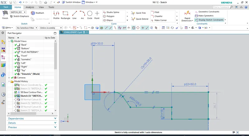
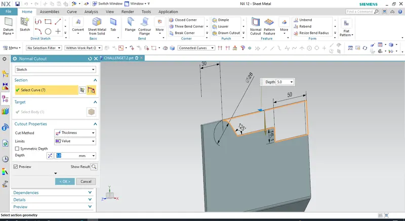
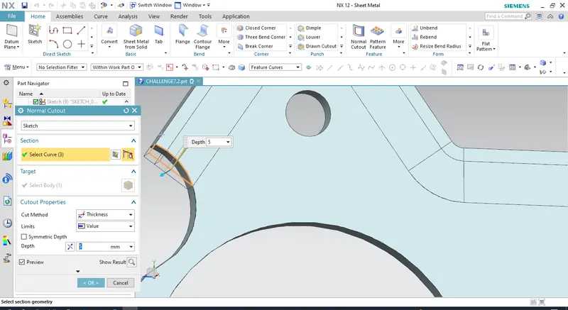
Draw a new sketch on the tab surface, with required dimensions. Use quick trim to remove the unwanted edges, then use normal cutout select the curve and input parameters then apply changes.
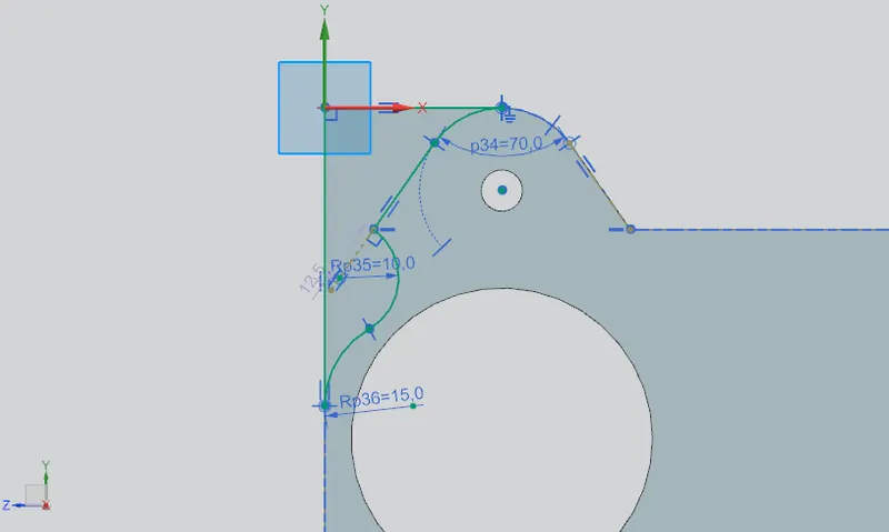
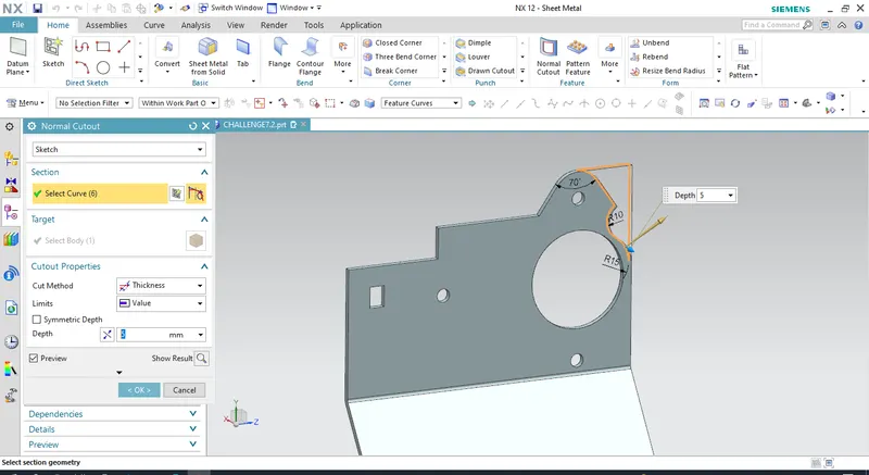
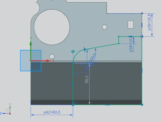
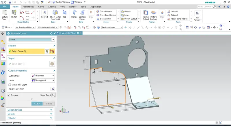
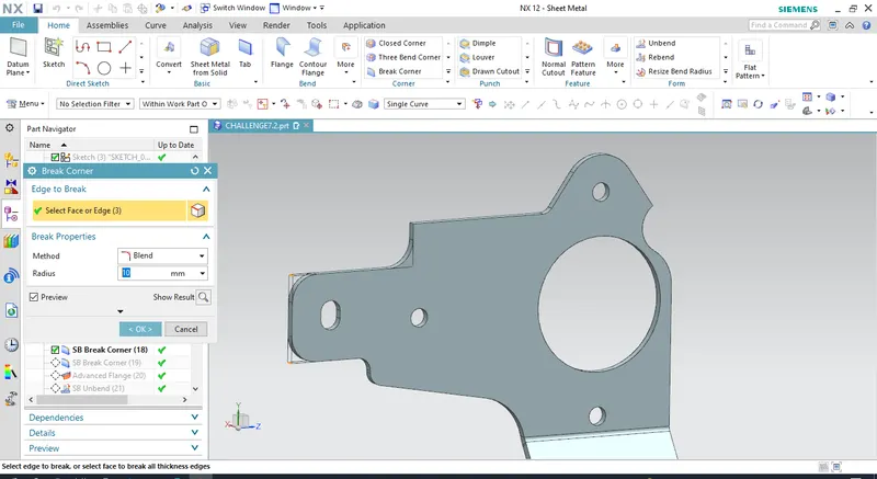
Use BREAK CORNER to round the edges at the required areas.
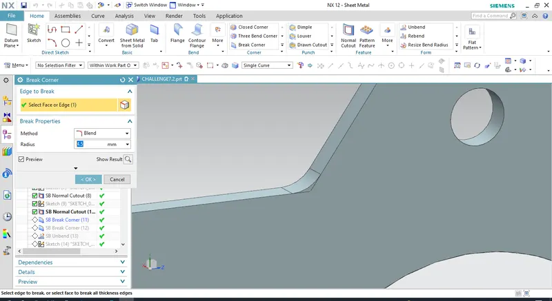
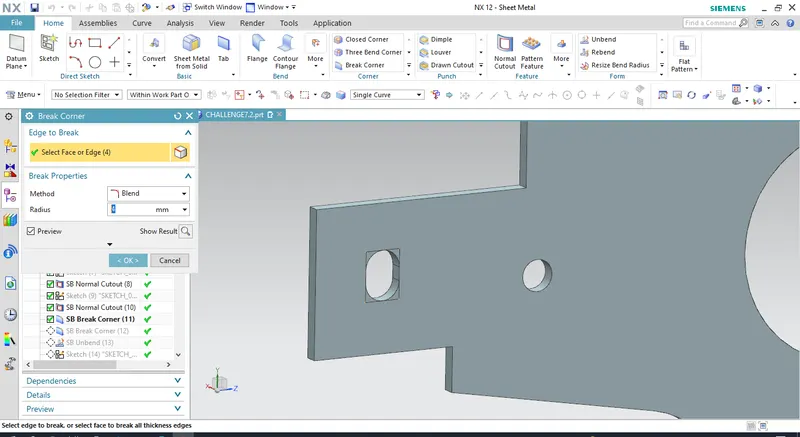
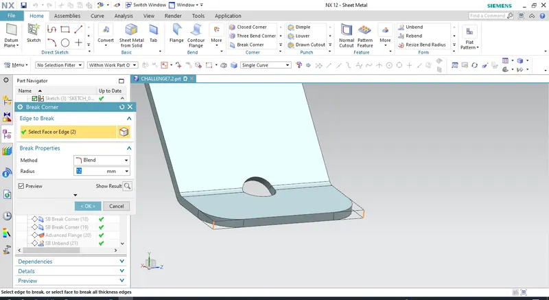
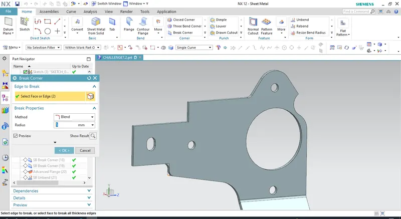
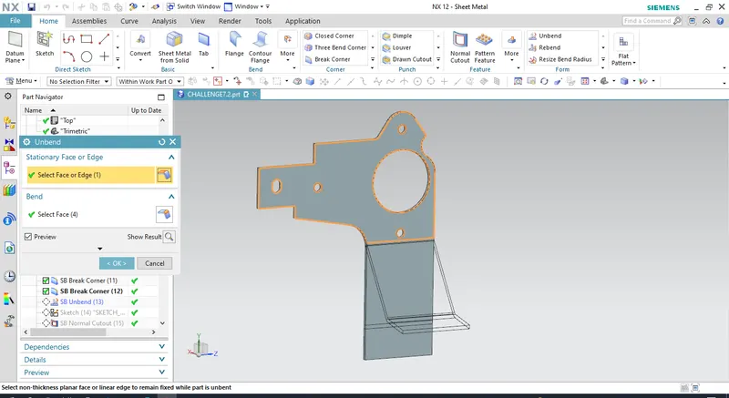
UNBEND the sheet metal part and add cutouts ands holes as required per design.
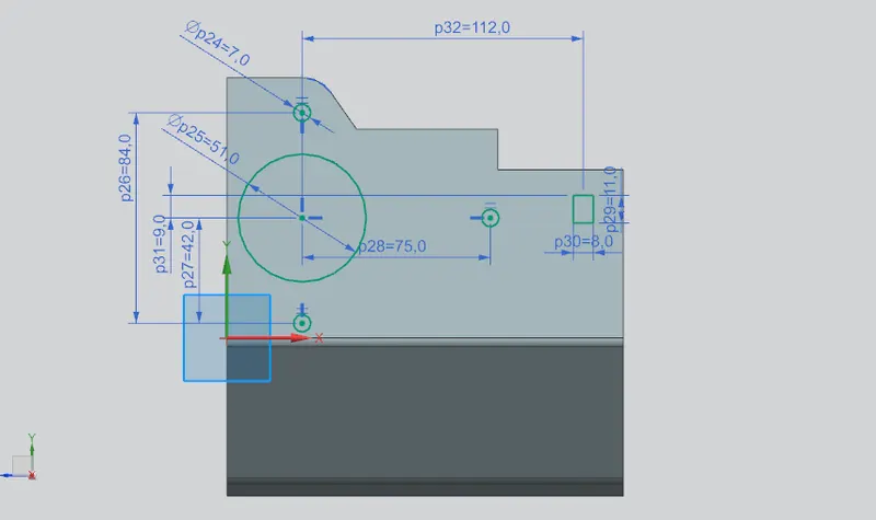
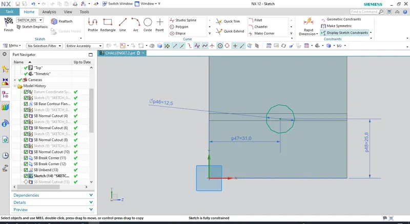
Draw a sketch to create a cutout.
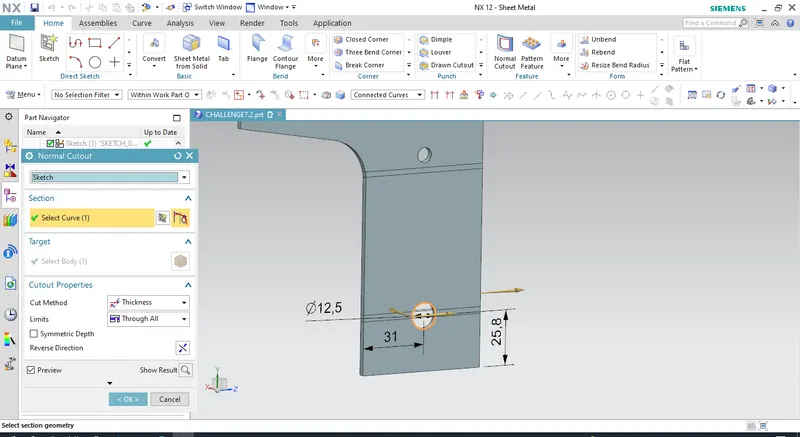
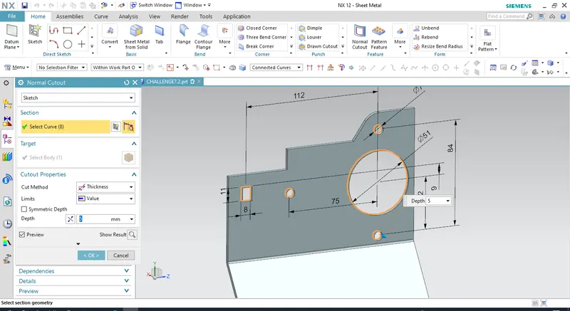
Create holes at the bottom of the part, by sketching and specifying points where to create holes. Give the diameter you requir and the other inputs.
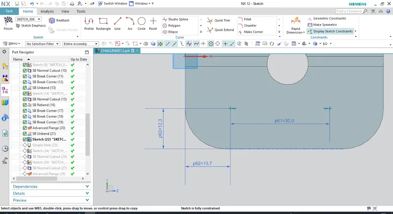
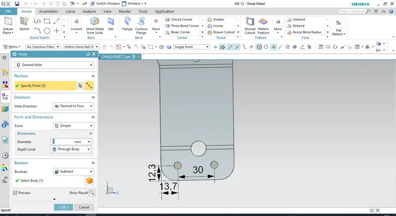
Draw a new sketch on the surface of the model, draw a rectangle with the given dimensions and then use fillet to round the corners of the rectangle.Then use normal cutout and then select the sketch, this removes the material inside the sketch.
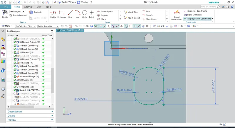
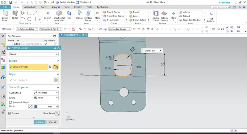
Using sketch and normal cutout remove the extra material at the to of the model for round finish.
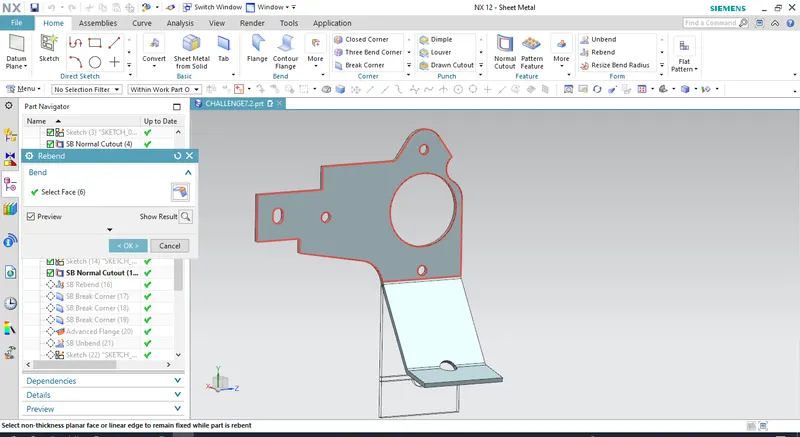
REBEND the sheet metal part.
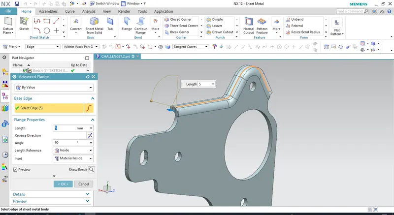
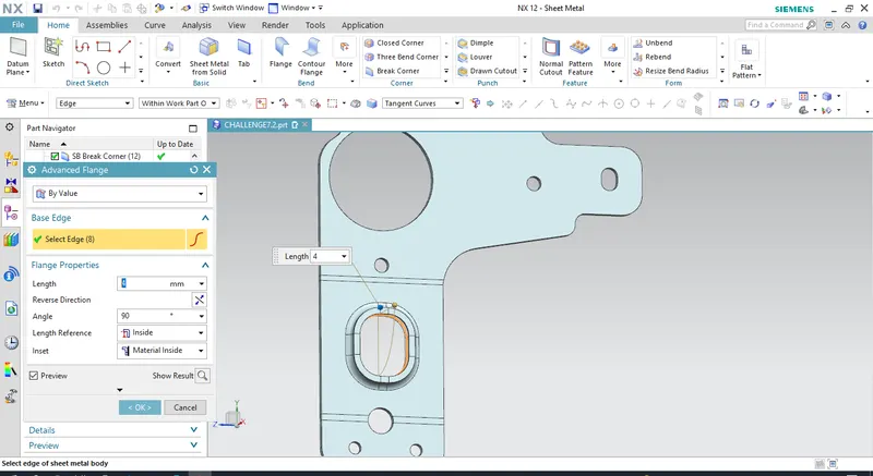
Use ADVANCE FLANGE to create a flange along the cutout area. Advance flange adds a flange along the edge of the curved surfaces.
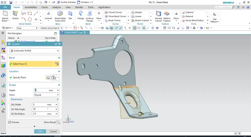
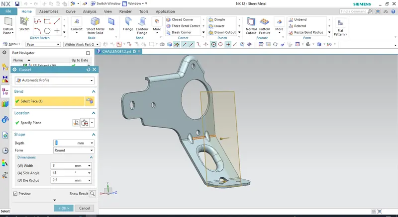
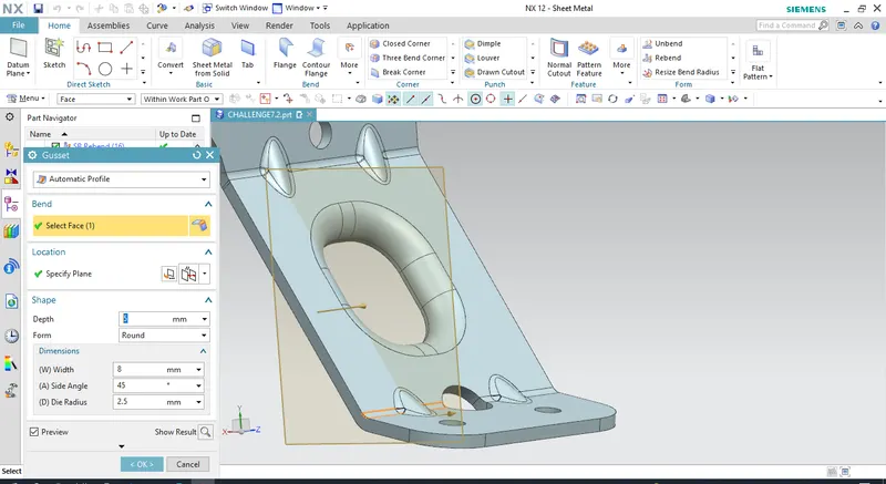
Add GUSSET, Gussets adds stiffness to the sheet metal part. now to add gusset select the bend face, and select the plane normal to the bend face.
The design of bracket is fineshed now create a flat pattern selecting a stationary face.