Advanced Sheet Metal Design Using NX Cad Challenge_7_ Metal bracket-II
DESIGNING OF METAL BRACKET
AIM: The aim of this project to design metal bracket in sheet metal using NX CAD software.
DESIGNING FEATURES:
contour flange: The feature that creates a base by extruding a sketch along a direction is called contour flange.
normal cutout:It helps in cutting out the material by drawing a sketch onto the model.
unbend:It is used to flatten the material part and its adjacent surface.
rebend: This feature helps to undo the operationn performed by unbend.
hole: It is used to add a hole in the solid body of the part.
break corner: This feature is used to smoothen the corner with some radius.
advanced flange: It adds flange along the edge curve with bend angle or reference face .
gusset: This feature is used to stiffen the curve similar to bead
DESIGNING STEPS:
SKETCH`to`CONTOUR FLANGE `to`SKETCH for cutting material `to`use NORMAL CUTOUT(Repeat the step for back and front )`to`SKETCH for the circles and perform normal cutout
`darr`
save the file as stp `larr`making gusset`larr`rebend`larr`hole creation`larr`unbend the curve`larr` use ADVANCED FLANGE `larr` use BREAK CORNER
(to get smooth corner)
VARIOUS ORIENTATION OF MODEL:
SIDE VIEW:
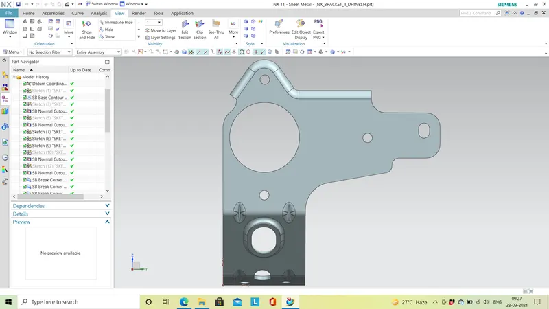
FRONT VIEW:
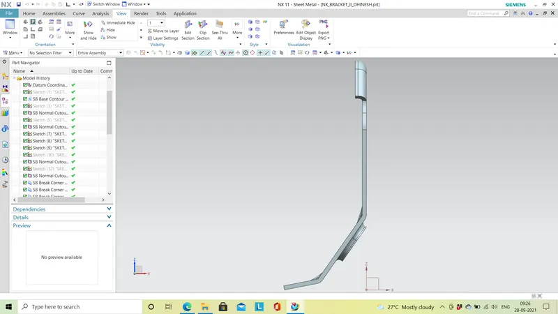
LEFT SIDE VIEW:
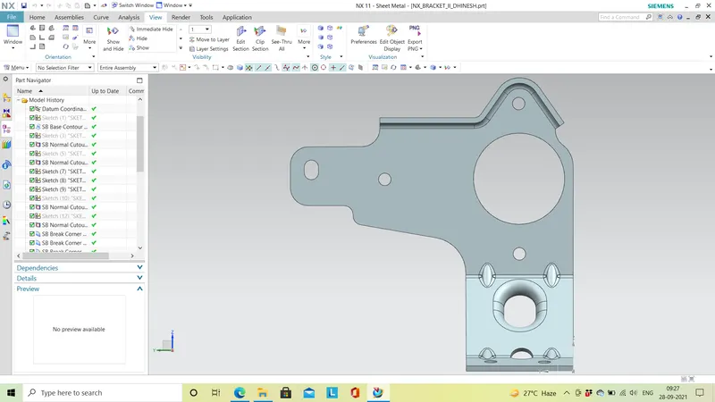
ISOMETRIC VIEW:
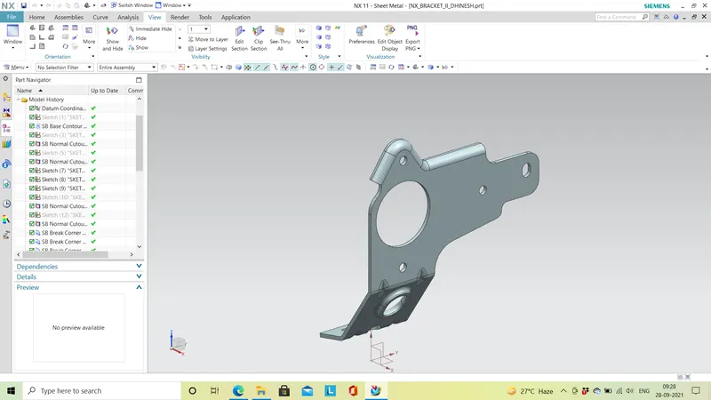
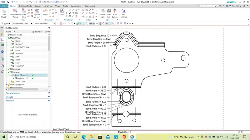
DRAWING SHEET IMAGE:
CONCLUSION:
Designing of metal bracket with given dimensions in sheet metal is created successfully.
The images of the model at various orientations are attached in the answer dialog box.