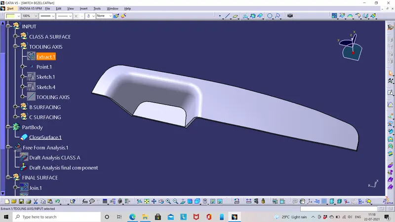
Week 8 - Challenge 3 - Switch Bezel Design
DRAFT ANALYSIS :
ON CLASS-A SURFACE:
AIM: To analyze the draft angle created in the class A surface with the help of tooling direction.
PROCEDURE:
TOOLING axis CREATION:
Tooling axis created usually by bisecting method from creating two lines in the surface,but in this case of switch bezel we have an open on the other side thereby we have a three surfaces in order to solve this situation we have to create an additional sketch in the class A as below.
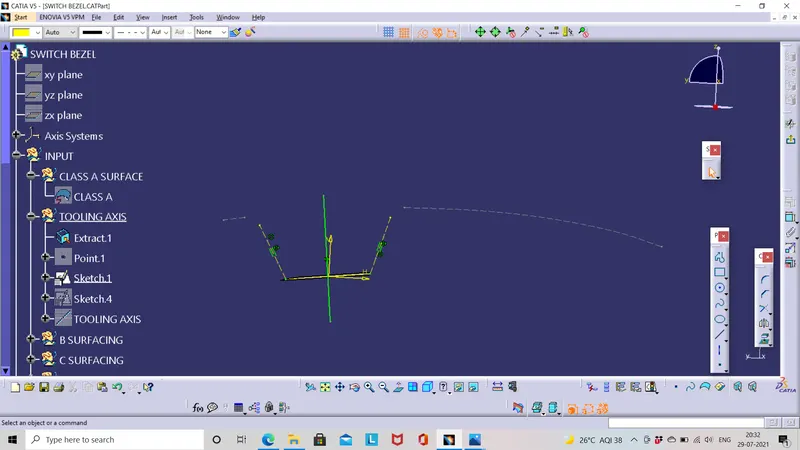
this image shows the second line by creating an additional sketch:
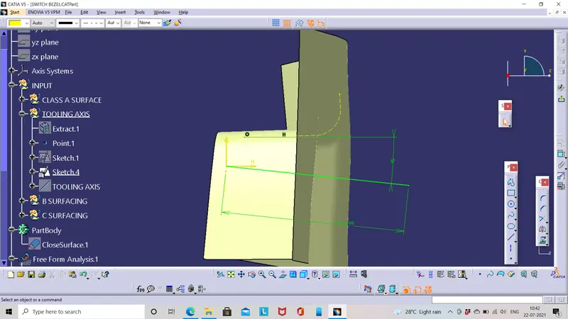
after creating the sketch we have to bisect the line as a result we get two bisecting lines in the respective axis direction,we get the main tooling axis by bisecting the two resultant lines and publish it for easy access.
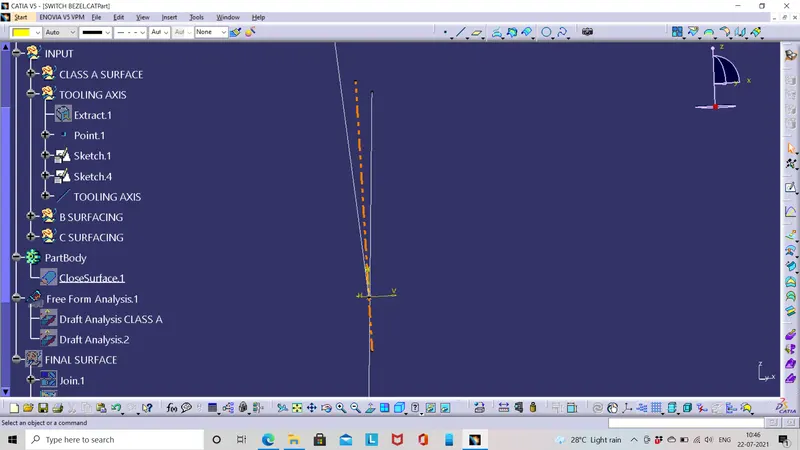
DRAFT ANALYSIS:
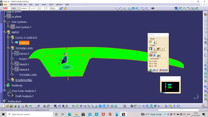
Feature draft analysis is done on the class A surface after the completion of tooling axis creation,make sure the surface is in customize view and chose the material.In the draft analysis dialog box pick the compass and align it with tooling axis and confirm the direction.Minimum draft angle is about to not exceed 3 deg. The color code to keep in mind is red and blue which gives the negative and range draft value needs to be corrected,after completing the draft analysis click ok to finish the process.
ON FINAL PLASTIC COMPONENT:
AIM: To analyze the draft angle created in final plastic component with the help of tooling direction.
PROCEDURE:
TOOLING DIRECTION CREATION: Tooling axis used for draft analysis for the draft analysis can use the previously created in the class a surface since only difference is thickening the component,there will be no change in it.
DRAFT ANALYSIS:
Feature draft analysis is done on the class A surface after the completion of tooling axis creation,make sure the surface is in customize view and chose the material.In the draft analysis dialog box pick the compass and align it with tooling axis and confirm the direction.Minimum draft angle is about to not exceed 3 deg.here you have to make sure the thickened component is also drafted with class A surface or else you have re-do the process ,whenever you make a change in the construction of the surface due to close surface,boundary or any other peoblem,after the correction we have do again the draft analysis.
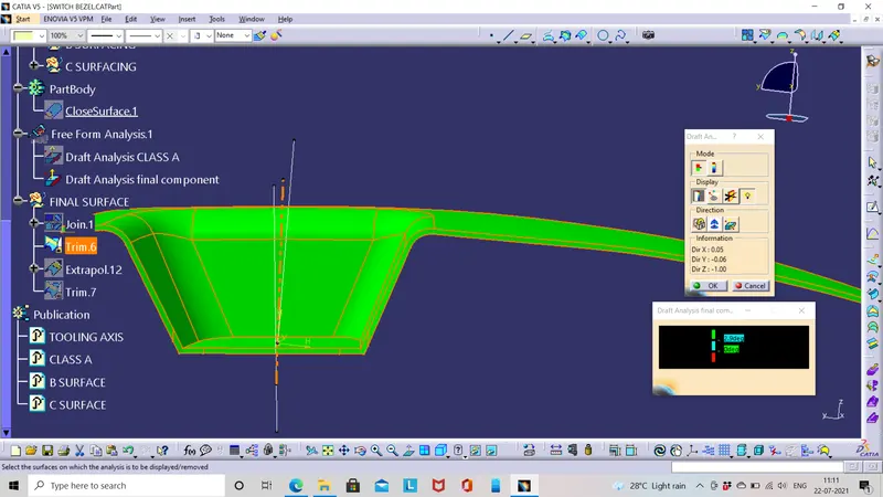
In this draft we have a thickened component which differs from class A you can alter the degree of draft analysis upto 3 deg.After placing the compass aligned with tooling axis lock the view using the lock symbol in the dialog box.
MULTI VIEW:
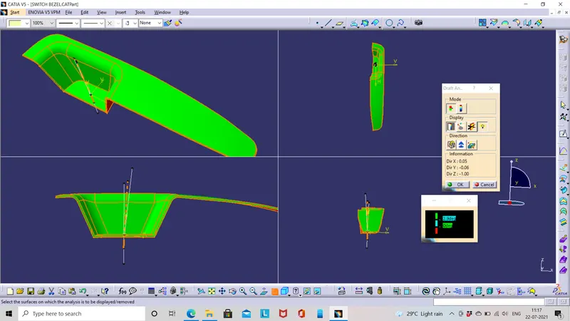
The image of final component in various orientations with draft analysis is shown below.
FINAL SOLID COMPONENT :
The closed surface of the component is used for the manufacturing purpose once you designed the component have to be a solid which is done using close surface tool in part design .