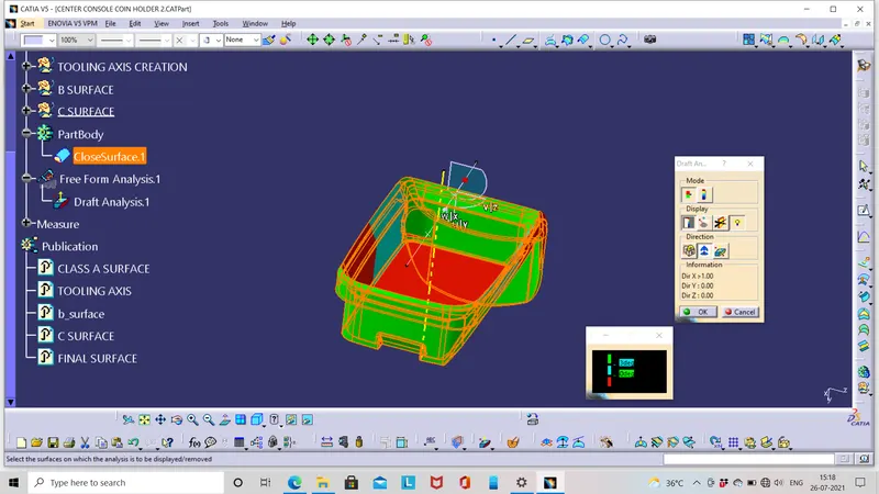
Week 8 - Challenge 4 - Coin Holder Design
AIM: To create the b surface and c surface for the given the class A surface and make an draft analysis on the final component and class A.
OUTCOMES: By finishing this component you will get a knowledge on how to thicken A surface with b surface and will also gain experiencd on draft analysis with main tooling axis and slider axis.
TOOLING AXIS CREATION: The tooling axis is created by creating point on extracted surface and make a line on point , it is advisable to create the tooling axis with bin and hole on the surface if applicable here we have bin wall at 90 degree so this method is used.
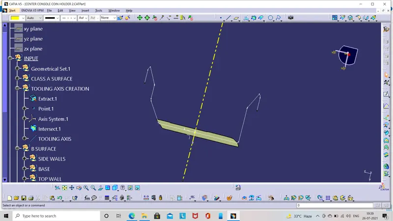
We can also create tooling axis using bisecting method by creating lines on the intersected bin wall,but it also gives the same result as the previous one which is given below.
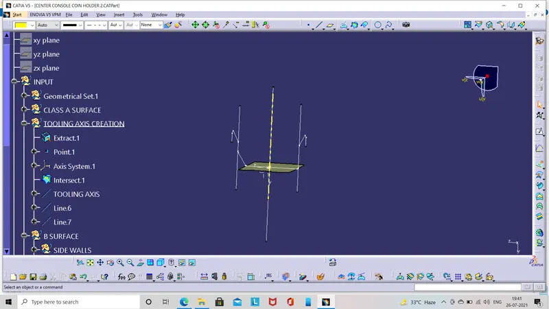
B SURFACE CREATION:
The b surface is created with reference to the a surface (using extract or multiple extract) ,the extracted surface is shown below.Be cautious while choosing the surface it is not suggested to choose the fillet faces it may give error in creation.
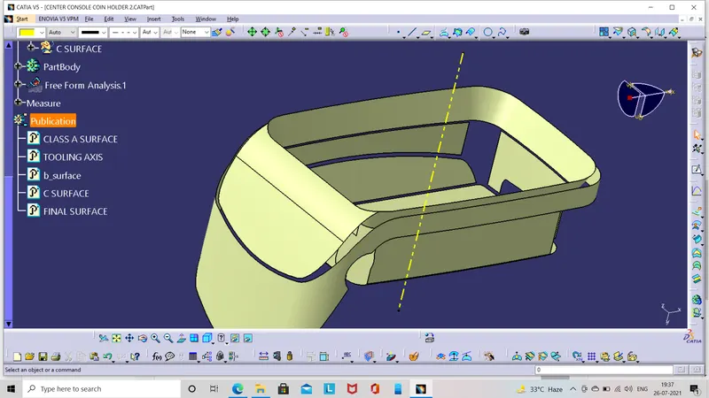
The final b surface is created from the above image and as shown below,fillet values are provided by measuring the fillet value in the a surface and be aware while giving the fillet value consider the thickness of the surfaces,if it is inside the a surface subtract the thickness value and vice versa.
C SURFACE CREATION:
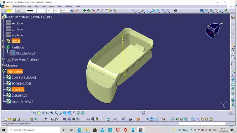
The C surface is created to join the A surface and B surface make it as a closed surface,the intersection of A surface and B surface shows that C surface should be created perpendicular to the tooling axis so while sweeping the angle must be 90 deg to achieve the requirements.
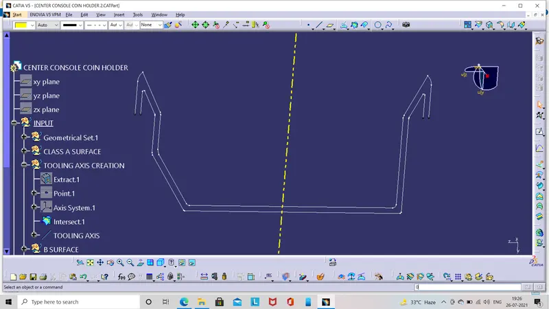
The image shows the created C surface,the component should be joined with A surface:
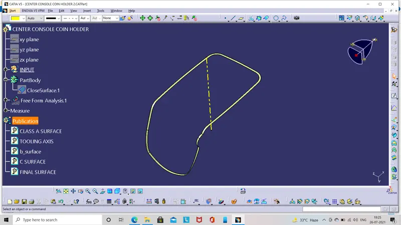
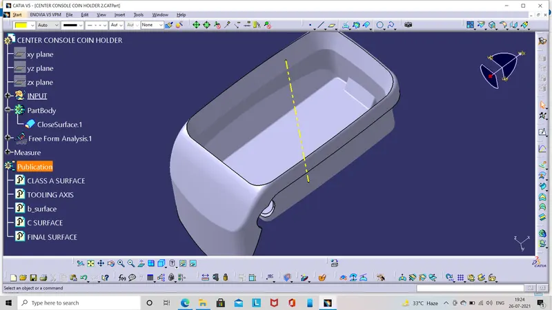
The joined surface should be trimmed with b surface to get final component and make as solid in part design using close surface feature.
DRAFT ANALYSIS:
ON CLASS A SURFACE:
The draft analysis is done on the class a using main tooling axis and slider direction with draft angle as 3 deg which is suggested value.
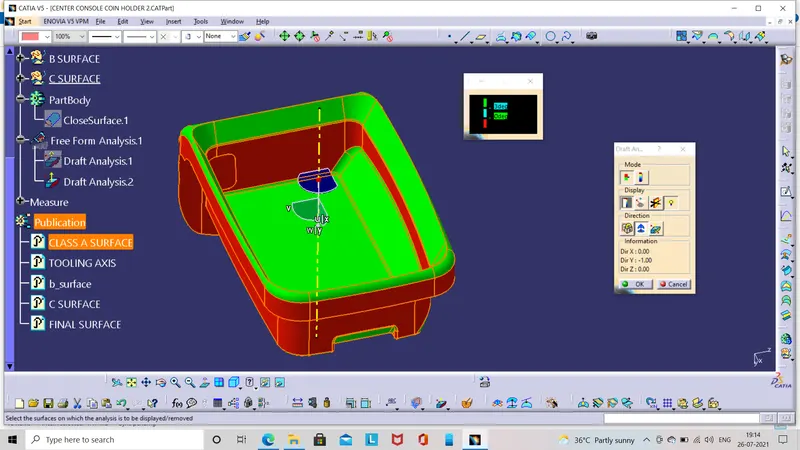
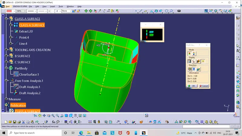
ON THE FINAL COMPONENT: The draft analysis is done on the final component using main tooling axis with draft angle as 3 deg which is suggested value.
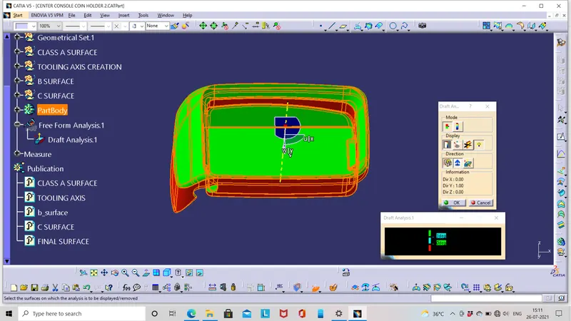
the full component can't be analysed with single tooling axis so the slider direction is created