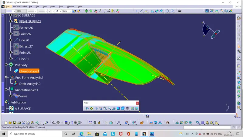
Door Arm Rest Week 8 Challenge
DOOR ARM REST:
AIM: To create the door arm rest with thickness as a solid having door as reference and make an draft analysis on the close surface .
PROCEDURE:
TOOLING AXIS CREATION:
The main tooling axis of the component is created here.We have to select opt view which encloses maximum part for tooling the component and create the toolong axis by sketch and bisecting method.
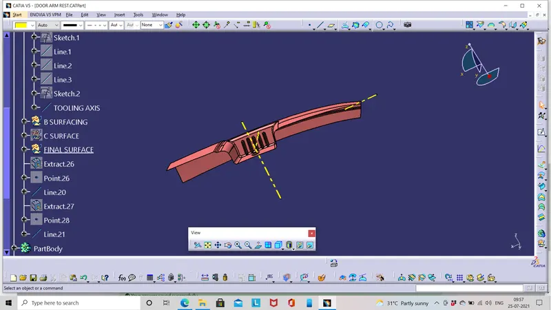
the axis one near the hole is main tooling axis other is called as slider axis which will be used while draft analysis.
CREATING B SURFACE:
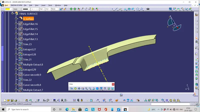
B surface is used for thickening the class a surface since it is only a aesthetic surface,the engineering features are incorporated in the b surface we have to divide the compponent into two parts and extract for b surface creation and then connectedd by trim or join operations.The following image depicts first part and second part of b surface.
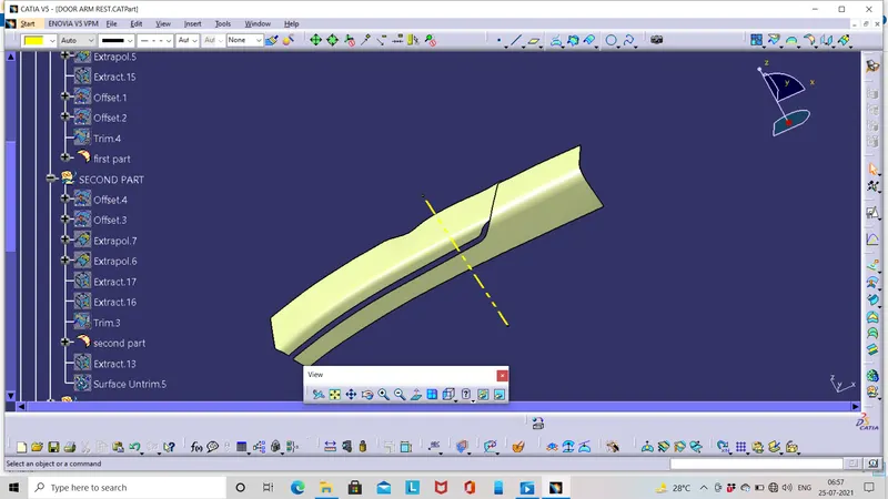
The two parts are filled by the connector which is creadted separately by sweep and blend operations.
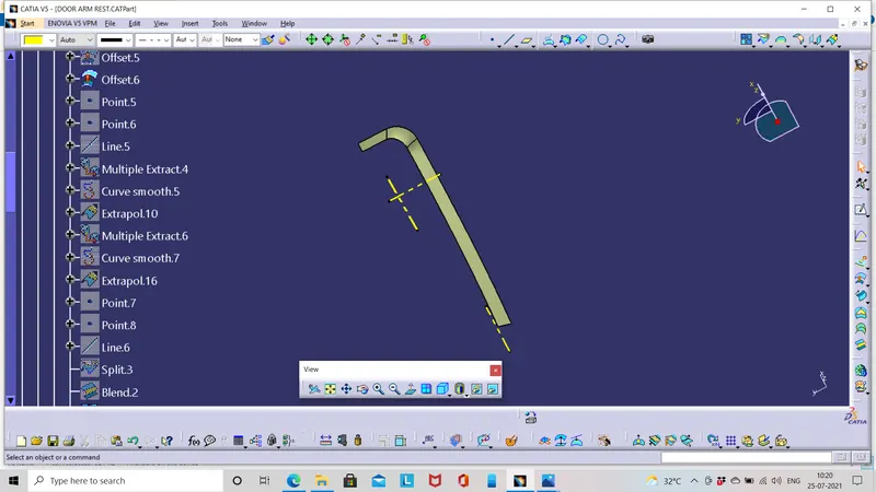
The complete finish of b surface is as follows:
C SURFACE CREATION:
After completion of b surface in order to get a closed surface we must create C surface with boundary chosen from the class A surface.
The C surface creation can not be done on a single extract ,done on two parts.The curved parts can create with unequal shapes as follows:
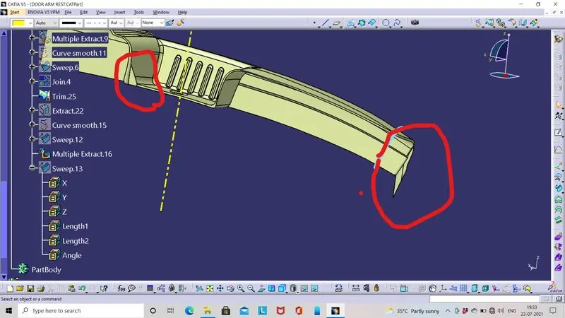
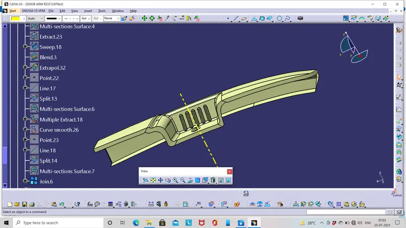
There a line can be created using point and split then create a sweep with the multiple extract ,it create a more smooth surface and can be trimmed with b surface.The final c surface can be created and it's image is as follows:
FINAL SURFACE CREATION :
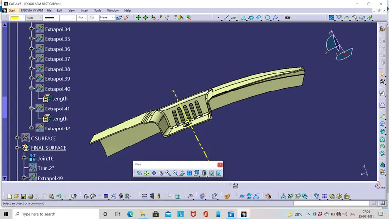
Join the A surface and C surface make them a single component .The final surface with thickness 2.5cm can be created by trimming the b surface which is offseted from A surface at 2.5cm with join surface and it look like as follows:
DRAFT ANALYSIS REPORT:
The draft analysis of the component can not be done on a single tooling axis in order to get the total component with draft angle. The draft analysis with the main tooling axis in the component can be done and there are some undercuts in the close surface which is shown in red color and blue color for that tooling axis . The draft angle for the component can be maximum 3 deg.
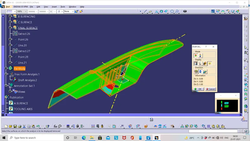
To get the undercuts corrected we should use a differnt tooling axis,the slider direction the axis created along the Y direction of the component when we draft analyse the component using slider direction the undercuts get corrected and get draft analysed.
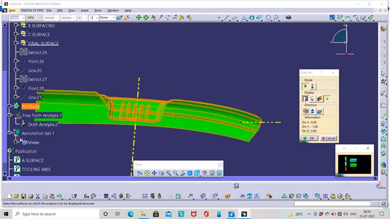
The following image depicts draft analysis of componenet using tooling axis created in side wall.