Advanced Sheet Metal Design Using NX Cad Challenge_7_ Metal bracket-II
Designing a sheet metal bracket 2
Objective
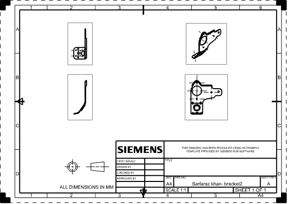
The objectives of the project is to design a sheet metal bracket using sheet metal application in Siemens NX software along with a detailed drawing sheet.
Introduction
Sheet metal is a metal formed by an industrial process into thin, flat pieces. Sheet metal is one of the fundamental forms used in metalworking, and it can be cut and bent into a variety of shapes. Countless everyday objects are fabricated from sheet metal.
A sheet metal bracket is nothing but a projection from a wall or overhangs from the wall to carry a weight. Brackets are often in the form of volutes, or scrolls, and can be carved, cast, or molded. These are manufactured by conducting stamping or die casting operation. These brackets found their application for mounting of any products starting from antennas to TV, projectors or street lights and many more.
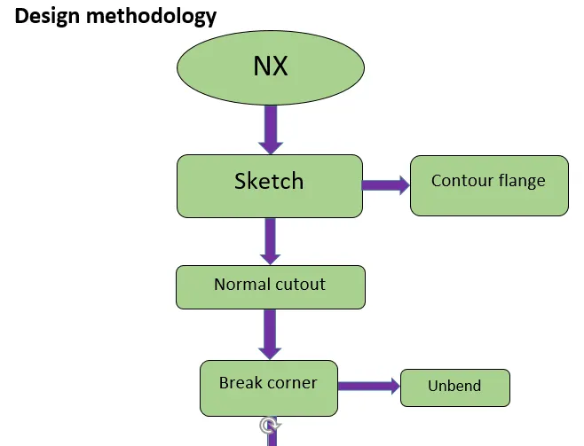
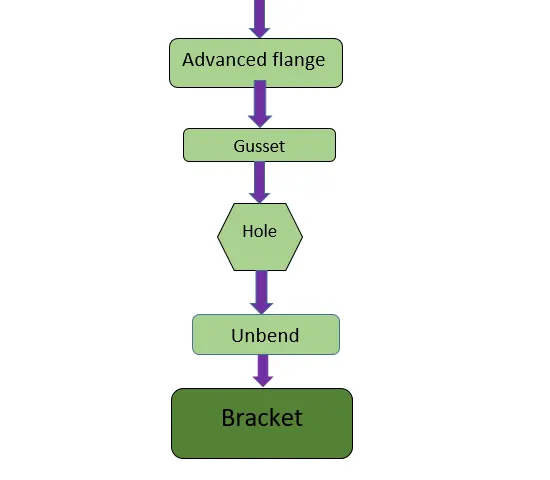
Description
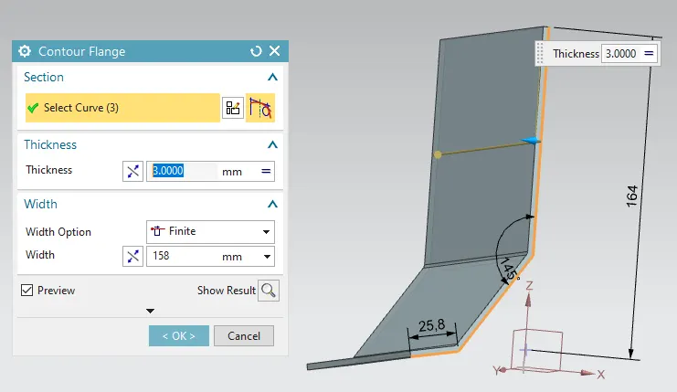
- Contour flange
Creates a base feature by extruding a sketch along a vector or adds material by sweeping a sketch along an edge or chain of edges.
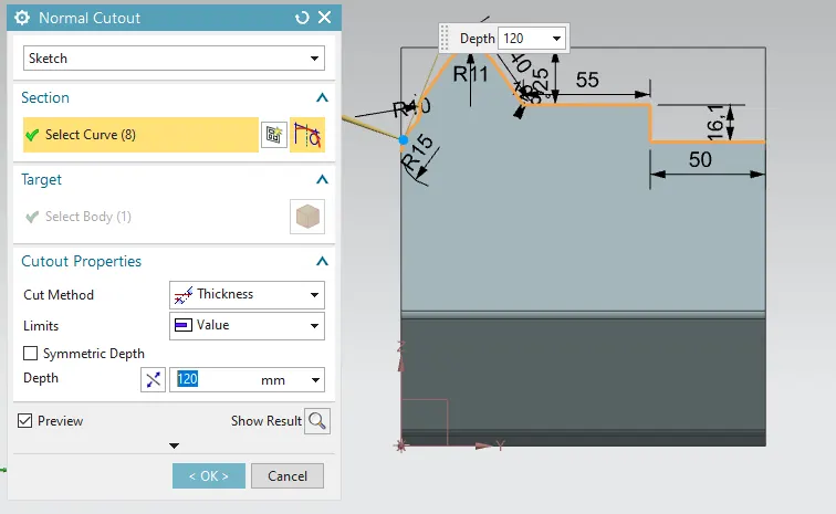
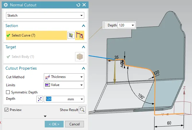
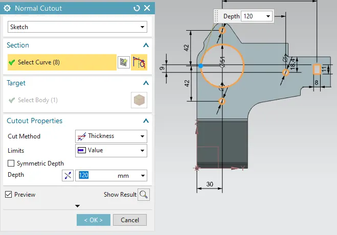
2.Normal cutout
Cuts material by projecting a sketch onto the model and then cutting perpendicular to the faces intersected by the projection.
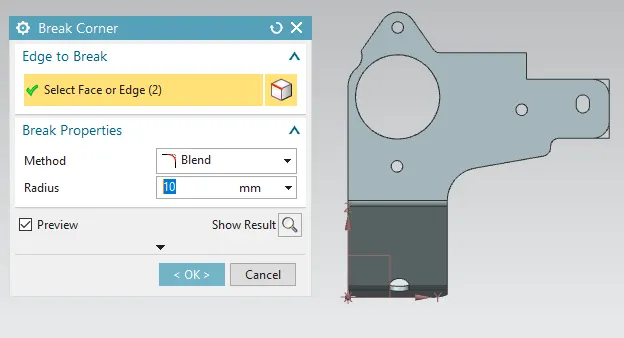
3.Break corner
Rounds or chamfer a sharp corner of a tab or flange.
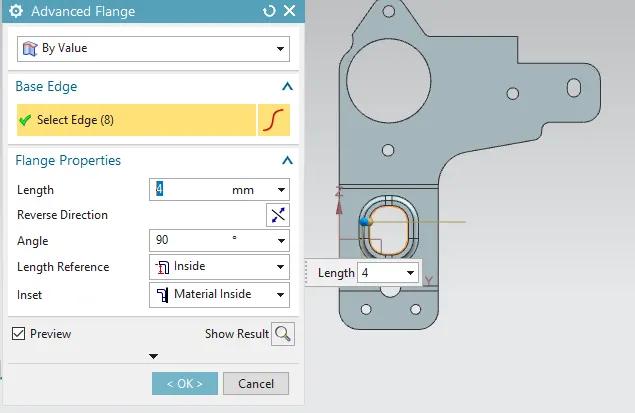
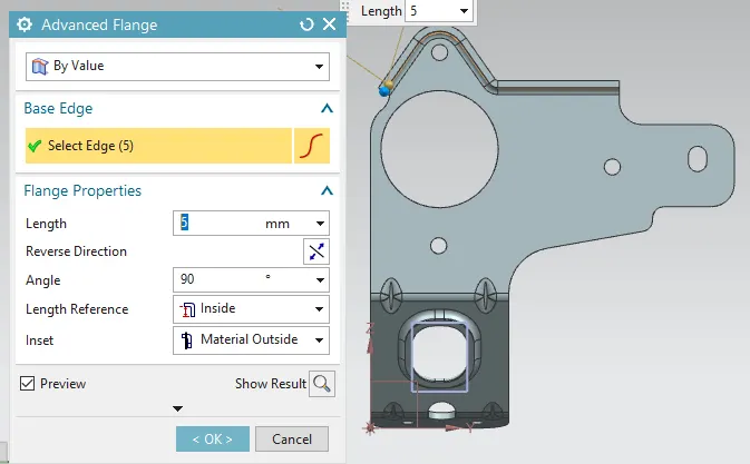
4. Advanced flange
Use to add a material at edge and give the length and angleas required.
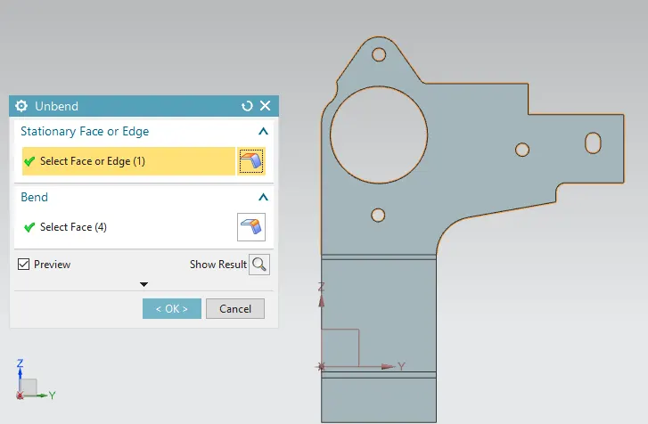
5. Unbend
Flattens a bend and the material adjacent to the bend.
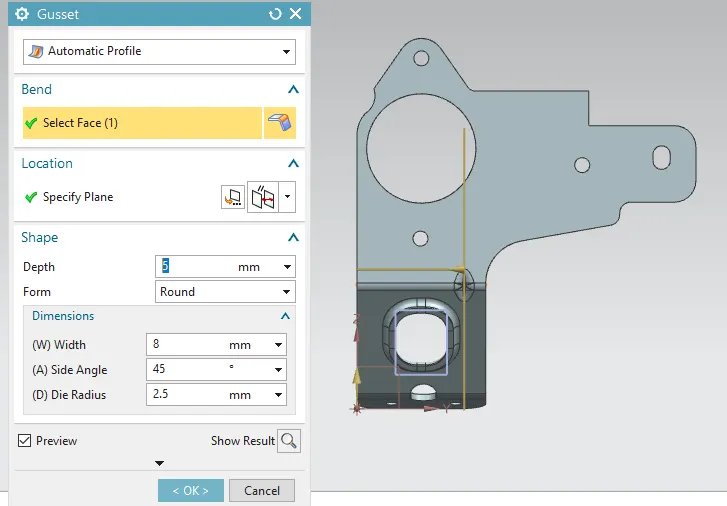
6. Gusset
it is the feature added to give the stiffness to the bend areas hence increasing the strength to the part.
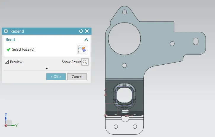
7. Rebend
Restores an unbend feature to its previous bend state, along with any features added after the unbend surface.
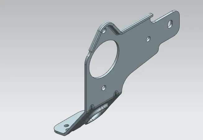
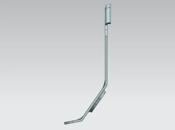
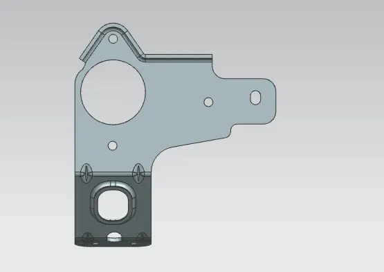
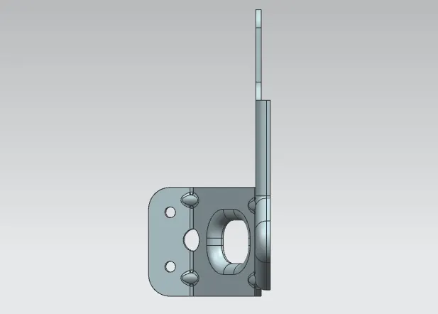
screeenshots of diffferent views.
1.Isomteric views
2.front view
3. Right view
4. Top view
5. Drafting
Conclusion
Thus the project has been completed by designing a sheet metal bracket using the sheet metal application in Siemens NX and the required drafting was also done using the drawing application in NX.