Photo Realistic Rendering
DESIGN AND ASSEMBLY OF AMERICAN CHOPPER REOR
By
Sarfaraz khan
Objective:
- The objective of this project is to create a model of different parts of the chopper using solid works.
- To Assemble the different parts of the model for the chopper.
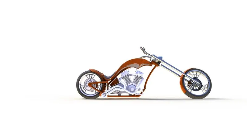
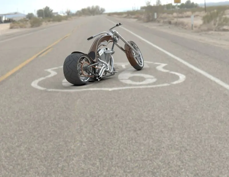
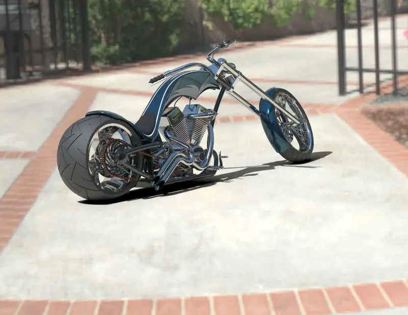
- To create a photorealistic model of the chopper and render the model using photo view or SolidWorks visualize.
Introduction
American Chopper is an American reality television series that airs on Discovery Channel, produced by Pilgrim Films & Television. The series centers on Paul Teutul Sr. (frequently called Senior), and his son Paul Teutul Jr. (also known as Paulie or simply Junior), who manufacture custom chopper-style motorcycles. Orange County Choppers is in Newburgh, New York. The contrasting work and creative styles of the father-and-son team and their resulting verbal arguments were the series' hallmark until 2008 when an explosive argument led to Paul Jr.'s termination and departure to start a competing chopper company, Paul Jr. Designs.
In this project, we learn to model the parts and assemble the parts and give a realistic image to chopper.
Parts of the chopper to be modeled:
- Transmission belt
- Kickstand
- Front fender
- Oil tank
- Pedal
- Chain
- Front-wheel
- Rear-wheel
- Front fork
- Chassis
- Engine
- Gas tank
Design methodology
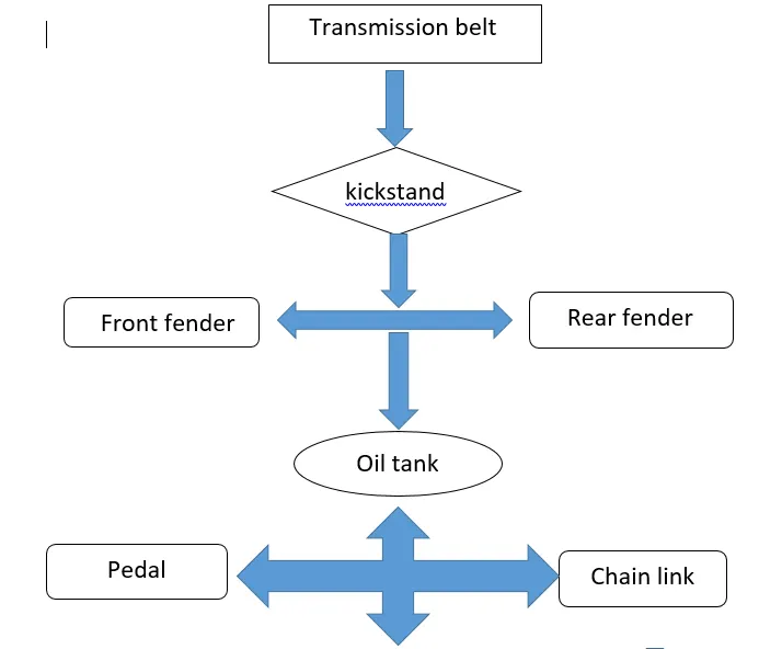
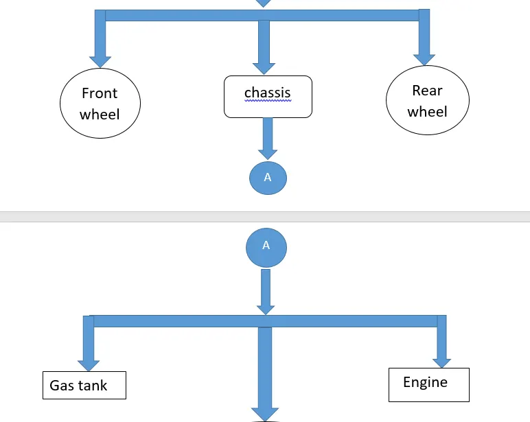
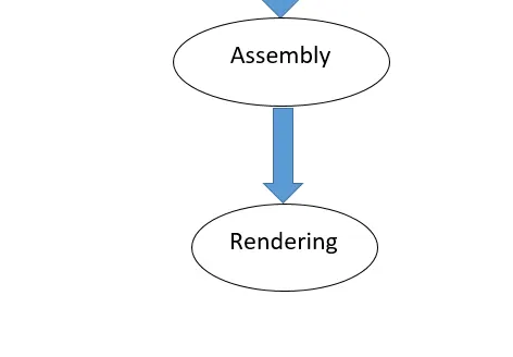
Features used during modelling the parts:
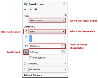
- Extrude Boss: The Extruded Boss is the most basic of all SOLIDWORKS features and extrudes a sketch along a straight-line path to add material. As a sketched feature, it requires a sketch before use. Once the sketch has been created, exit the sketch and select the Features tab of the Command Manager. Then, click the Extruded Boss/Base command. If a yellow dialog box appears in the Property Manager asking you to create a new sketch, don’t worry – simply click on the sketch in the graphics area to use it for the feature. The Property Manager for the Extruded Boss allows you to control starting location, extrude depth and draft for the feature, among several other parameters:
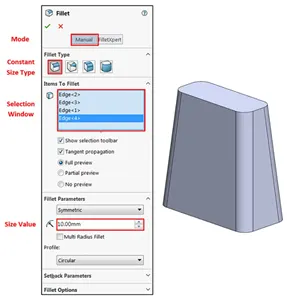
- Fillet: Fillets are classified as applied features, and as such do not require a sketch to be used. Fillets serve to round off edges and/or corners by adding or removing material, depending on whether the edge is internal or external. It should be noted that fillets of different sizes must be created as separate features. Typically, it is best practice to create the largest fillets first and follow with smaller fillets.
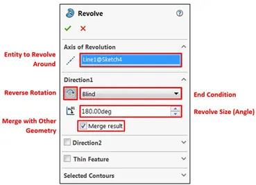
3. Revolved Boss Feature: Adds material by revolving a sketch around an axis. Remember, once geometry has been created in your model, any flat face can be used as a sketching surface. It is very important to draw an axis in the sketch which needs to be revolved.
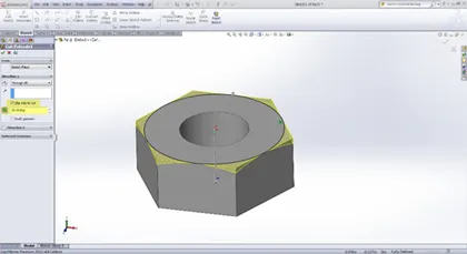
4.Extrude Cut: Similar to the extrude boss feature this feature needs a sketch on the solid body which needs to be cut and the desired shape is then cut off.
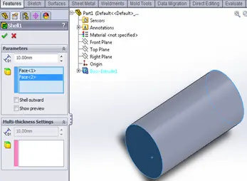
5.Shell: SolidWorks shell tool is mainly used for shelling process, in which the material removed from the inner body of model by keeping small thickness and results a hollow model. Using this tool, you can make either completely closed hollowed model or one face opened type.
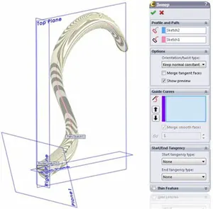
6.Sweep Boss / Sweep Cut: Sweep creates a base, boss, cut, or surface by moving a profile (section) along a path, according to these rules: The profile must be closed for a base or boss sweep feature; the profile may be open or closed for a surface sweep feature.
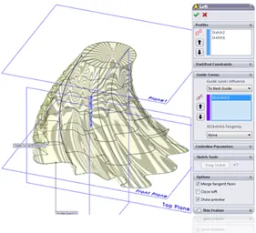
7. Loft Boss/ Loft Cut: The loft feature is an important tool for (surface) modelling in SolidWorks. The loft feature creates a shape by making transitions between multiple profiles and guide curves. This tool is very valuable for modelling complex surfaces. You can do some cool stuff when you use this feature properly.
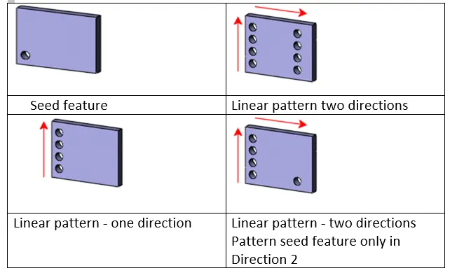
8.Linear Pattern: You can use linear patterns to create multiple instances of one or more features that you can space uniformly along one or two linear paths. Pattern instances inherit the visual properties of the original feature when you select Propagate Visual Properties in the Property Manager.
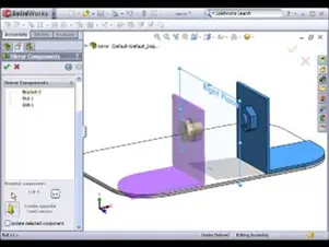
9.Mirror: Creates a copy of a feature, (or multiple features), mirrored about a face or a plane. You can select the feature, or you can select the faces that comprise the feature. Bodies to Mirror: Select a body in a single model or multibody part to create a mirror entity. Multibody parts: Apply features to one or more multibody parts by selecting Geometry Pattern and using Feature Scope to choose which bodies should include the feature.
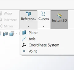
- Reference Geometry: Reference geometry defines the shape or form of a surface or a solid. Reference geometry includes items such as planes, axes, coordinate systems, and points. You can use reference geometry in the creation of several kinds of features. For example:
- Planes are used in lofts and sweeps.
- An axis is used in a circular pattern.
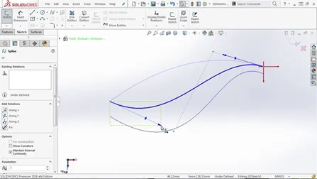
- Projected Curve: You can project a sketched curve onto a model face to create a 3D curve. You can also create a 3D curve that represents the intersection of two extruded surfaces generated by creating sketches on two intersecting planes. You can create multiple closed or open-contour projected curves from a single sketch. You can also use 3D sketches as input for the Projected Curve tool. Note: the Projected Curve tool does not support projections of intersecting curves.
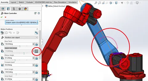
- Mate : Mates create geometric relationships between assembly components. As you add mates, you define the allowable directions of linear or rotational motion of the components. You can move a component within its degrees of freedom, visualizing the assembly's behaviour.
Some examples include:
- A coincident mate forces two planar faces to become coplanar. The faces can move along one another but cannot be pulled apart.
- A concentric mate forces two cylindrical faces to become concentric. The faces can move along the common axis but cannot be moved away from this axis.
Mates are solved together as a system. The order in which you add mates does not matter; all mates are solved at the same time. You can suppress mates just as you can suppress features.
- Transmission belt
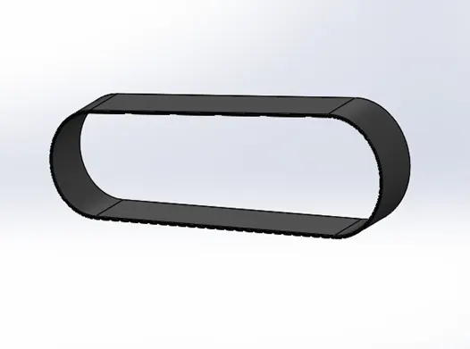
- The transmission belt in the chopper is used to transmit the power from the engine to the gearbox.
- Features used:
- Sketch
- Offset
- Extrude
- Fillet
- Appearances
2. Kickstand
- It is used to support the chopper it also known as a side stand
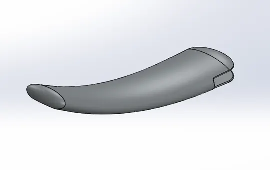
- features used:
- sketch
- loft
- dome
- Extrude boss
- Extrude cut
- Fillet
- Split
- Appearances
3.Front fender
- The front fender is the part mounted on the fork above the wheel to protect the rider and the chopper from debris and foreign particles.
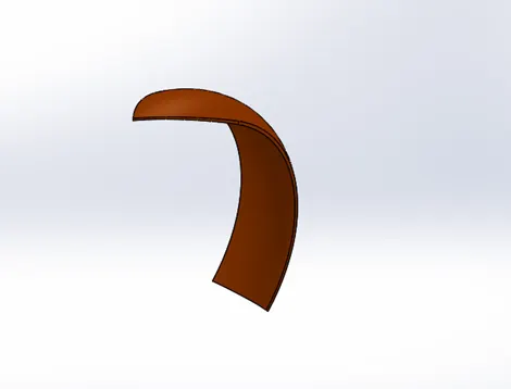
- Features used:
- Sketch
- Offset entities
- Trim entities
- Revolve
- Dynamic mirror
- Split
- Appearances
4.Oil tank
- An oil tank is used to store the oil required to run the engine.
- Features used:
- Sketch
- Boss extrude
- Combine
- Fillet
- Shell
- Appearances
5.Pedal
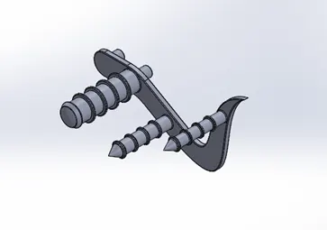
- The pedal is used to place the leg on top of that. to give comfort to ride the chopper.
- Features used:
- Sketch
- Extrude
- Fillet
- Linear pattern
- Dome
- Chamfer
- Appearances
6.Chain
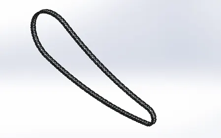
- Chain is a type of transmission system that is used to transmit the power from the engine to the rear wheel and it is made up of steel.
- Features used:
- Sketch
- Trim
- Fillet
- Blocks
- Extrude
- Patterns
- Appearances
7.Front-wheel
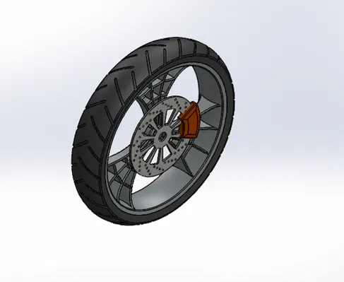
- A wheel is a circular block made of steel/alloy material. On the top of the wheel, the tire is covered.
- Features used:
- Sketch
- Revolve
- Trim
- Fillet
- Boss extrude
- Revolve cut
- Linear pattern
- Chamfer
- circular pattern
8.Rear wheel
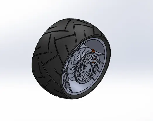
- A circular object that revolves on an axle and is fixed below a vehicle or other object to enable it to move easily over the ground .the chain is connected between the engine and rear wheel.
- Features used:
- Sketch
- Revolve
- Trim
- Fillet
- Boss extrude
- Planes
- Revolve cut
- Linear pattern
- Chamfer
- Fillet features
- Cut extrude
- Circular pattern
- Appearances
9.Front fork
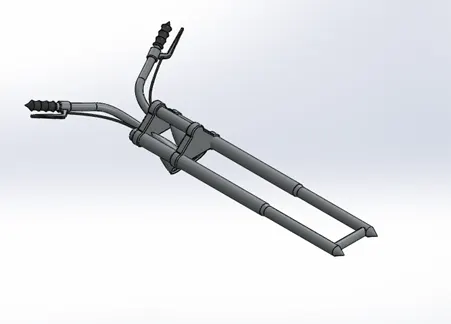
- The front fork holds the front wheel and is fixed to the chassis. They allow the front wheel to react to the imperfections in the road while isolating the rest of the motorcycle from that motion.
- Features used:
- Sketch
- Extrude
- Trim
- Revolve
- Split
- Plane
- Convert entities
- Move/copy body
- Dome
- Mirror
- Combine
- Curve(project curve)
- Sweep
- Appearances
10.Chassis
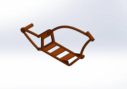
- A chassis or frame forms its skeleton. all the components of a motorcycle, like the suspension, wheels, fuel tank, seats, handle-bars, etc, are attached to this base structure which lends a motorcycle its strength and ability to handle well.
- Features used:
- Sketch
- Offset
- Convert entities
- Project curve
- Trim
- Plane
- Sweep
- Split
- Revolve
- Cut extrude
- Fillet
- Combine
- Appearances
11.Engine
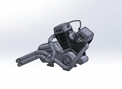
- The engine is the prime mover for the bike. the engine converts chemical energy into heat energy and then heat energy is converted into mechanical work. The mechanical work in the engine is rotational motion. this rotation is converted to the wheel with the use of the chain and sprocket through the gearbox and clutch.
- Features used:
- Sketch
- Convert entities
- Trim
- Revolve
- Boss extrude
- Cut extrude
- Offset
- Dome
- Fillet
- Project curve
- Composite curve
- Sweep
- Mirror
- Circular pattern
- Split
12.Gas tank
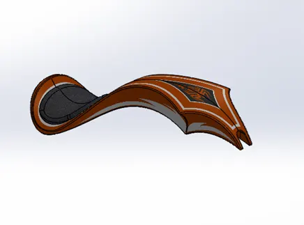
- Gas tanks are used to store the gas. to give the gas to the engine whenever it's required.
- Features used:
- Sketch
- Trim
- Project curve
- Convert entities
- Sweep surface
- Loft surface
- Fill surface
- Surface trim
- Surface knit
- Sweep cut
- Fillet
- Appearances
Assembly of chopper
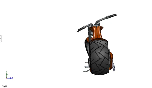
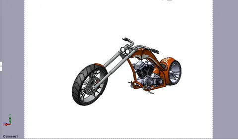
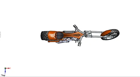
- Initially, the chassis is inserted in assembly by using insert parts in the option .after that the part is inserted in the assembly environment, and click ok to fix the chassis.
- After that, the other parts of the chopper are inserted into the assembly by using the possible mates.
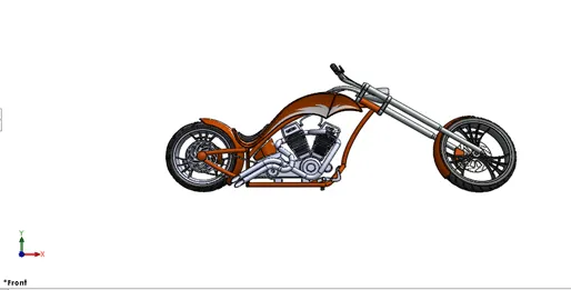
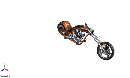
- Features used:
- mirror
- mates
- Coincident
- Distance
- Limit angle
- Parallel
- Tangent
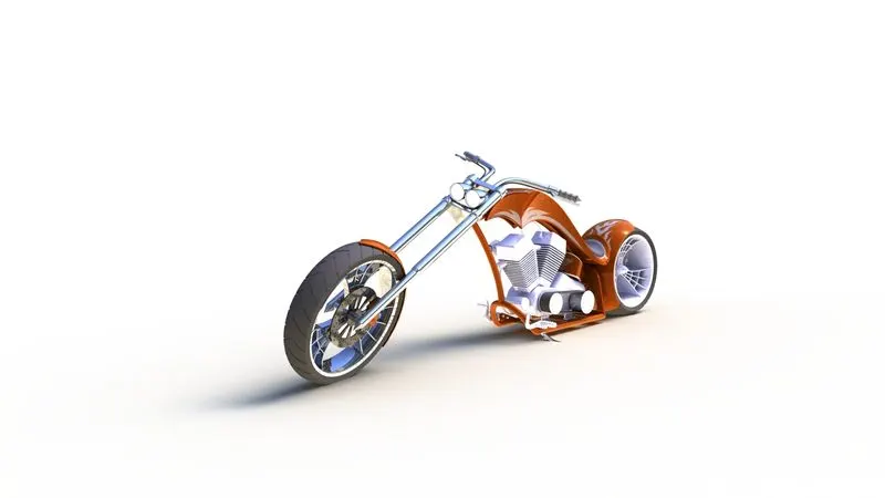
Rendering
- Rendering is the process of creating realistic images of the photorealistic model with the environment.
- Rendering has been done in two ways in SolidWorks i.e,
- Photo view 360
- Solidworks visualize
- In a photorealistic model, some mates and positions are changed to render a realistic model.
Conclusion
- The parts of the chopper are modeled.
- The parts are inserted in the assembly using the required mates and the chopper is assembled.
- The realistic image was rendered using SolidWorks visualize.