Advanced Sheet Metal Design Using NX Cad Challenge_1_Casing Design
CASING DESIGN USING NX CAD
Objective
To design an advanced casing using the sheet metal application in siemens NX.
Introduction
Creating sheet metal casing using NX cad I have various tools used to create casing were sketch, tab, normal cutout, bend, flanges, holes, break cobreaknbending , studio spline, move curve, dimple, bead, mirror feature, rebending, flat pattern, drafting.
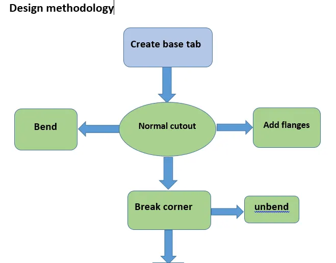
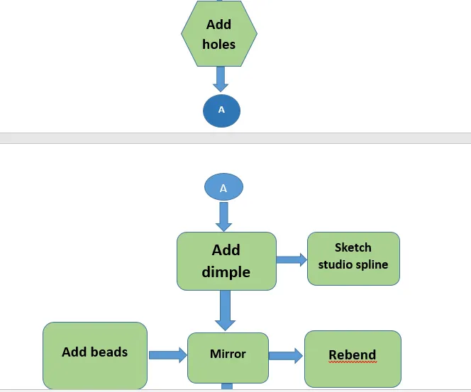
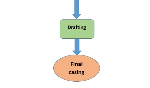
Description
- Tab
It is used this command to create a base feature by extruding a sketch along a vector by a thickness value, or by adding material to existing faces and bend region of a sheet metal part.
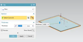
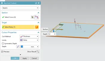
- Normal cutout
It is used to cut or create a gap in sketch.
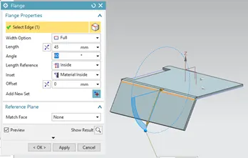
- Flange
It is used this command to add a flat flange at an angle to a planar face and add a bend between the two. A flange consists of a bend region and a web.
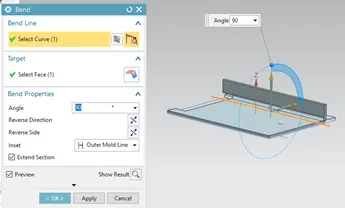
- Bend
Bend is used to create a bend in the flat body.
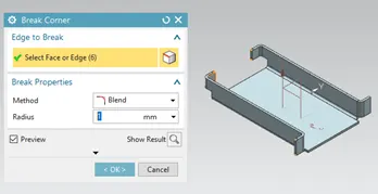
- Break corner
It is used to convert the sharp edges to the smooth edges of the corner.
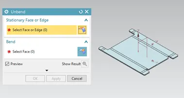
- Unbend
It is used for unbending corners of the body.
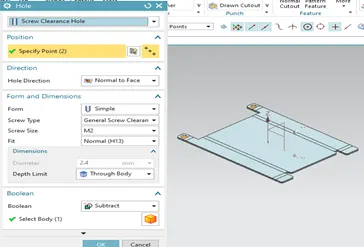
- Hole
A hole feature is used to create holes on the model.
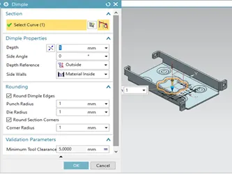
- Dimple
It is used to lift an area shown in sketch to make an impression on the sheet metal.
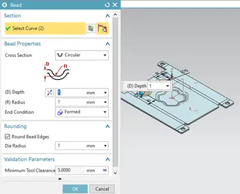
- Bead
It is used to create a contour shape according to the sketch in the required direction with required punch/die radius.
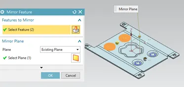
10. Mirror feature
This is used to mirror a feature along a specific direction.
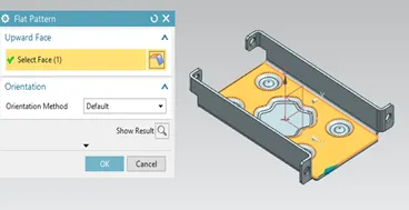
11.Flat pattern
Flat pattern is used to create flat pattern view which is used for drafting purposes.
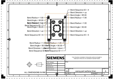
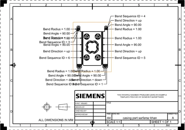
12. Drafting
It helps to create 2D drawing from a 3D model.
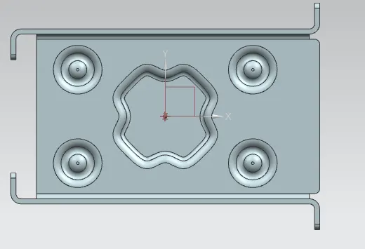
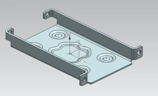
Screen shots of model
Top view
Isometric view
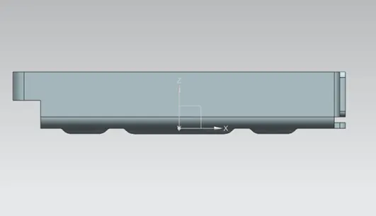
Front view
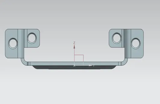
Side view
Drafting sheet
Conclusion
The casing was designed and drawings were successfully displayed in this project report. The model was designed and the drawings were created using Siemens NX.