Radar Mast & Final Assembly of Yacht
DESIGN AND ASSEMBLY OF YACHT REPORT
BY
SARFARAZ KHAN
Objective:
- The objective of this project is to create a model of different parts of the yacht using solid works.
- To Assemble the different parts of the model for the yacht.
- To create a photorealistic model of the yacht and render the model using a photo view.
Introduction
Solidworks is a mechanical 3D CAD (computer-Aided design) software used to create 2D & 3D models. It helps to design products better, faster, and more cost-effectively.Yacht modeling completely depends on surface modeling. In this modeling, the most important part is to set up the blueprint. Then as per the requirements of parts in the blueprint do the process to get the desired part.
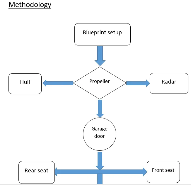
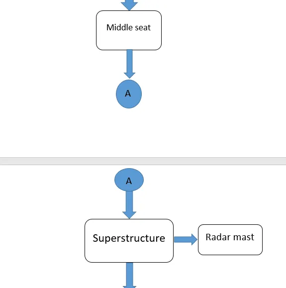
Parts of the yacht to be modeled:-
- Blueprint setup
- Propeller
- Radar
- Hull
- Garage door
- Rear seat
- Front seat
- Middle seat
- Superstructure
- Radar mast
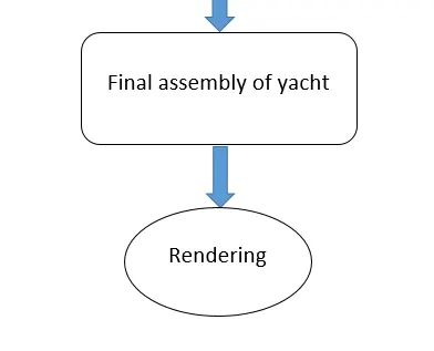
- Final assembly of yacht
Common tools used in yacht modeling
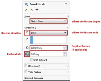
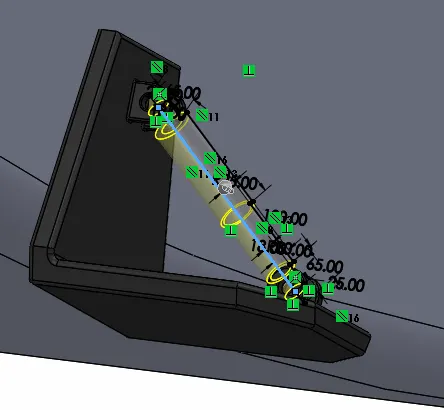
- Extrude Boss: The Extruded Boss is the most basic of all SOLIDWORKS features and extrudes a sketch along a straight-line path to add material. As a sketched feature, it requires a sketch before use. Once the sketch has been created, exit the sketch and select the Features tab of the Command Manager. Then, click the Extruded Boss/Base command. If a yellow dialog box appears in the Property Manager asking you to create a new sketch, don’t worry – simply click on the sketch in the graphics area to use it for the feature. The Property Manager for the Extruded Boss allows you to control starting location, extrude depth, and draft for the feature, among several other parameters.
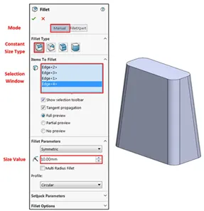
2.Fillet: Fillets are classified as applied features, and as such do not require a sketch to be used. Fillets serve to round off edges and/or corners by adding or removing material, depending on whether the edge is internal or external. It should be noted that fillets of different sizes must be created as separate features. Typically, it is best practice to create the largest fillets first and follow with smaller fillets.
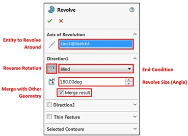
3.Revolved Boss Feature: Adds material by revolving a sketch around an axis. Remember, once geometry has been created in your model, any flat face can be used as a sketching surface. It is very important to draw an axis in the sketch which needs to be revolved.
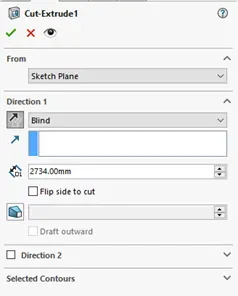
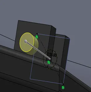
4.Extrude Cut: Similar to the extrude boss feature this feature needs a sketch on the solid body which needs to be cut and the desired shape is then cut off.
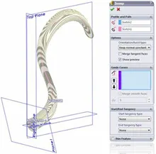
5. Sweep Boss / Sweep Cut: Sweep creates a base, boss, cut, or surface by moving a profile (section) along a path, according to these rules: The profile must be closed for a base or boss sweep feature; the profile may be open or closed for a surface sweep feature.
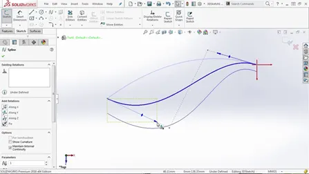
6. Projected Curve: You can project a sketched curve onto a model face to create a 3D curve. You can also create a 3D curve that represents the intersection of two extruded surfaces generated by creating sketches on two intersecting planes. You can create multiply closed or open-contour projected curves from a single sketch. You can also use 3D sketches as input for the Projected Curve tool. Note: the Projected Curve tool does not support projections of intersecting curves.
7. Surface extrude: Click Insert > Surface > Extrude.Select a face: To extrude from a 3D face, select a 3D face. To extrude from a 2D face, press Alt + select the planar face. You can select either a surface or the face of a solid body. You can also preselect the 3D faces to extrude before clicking Insert > Surface > Extrude. Select other faces to define the extrude as required. You can select faces that are not touching when you create a surface extrude in a given direction.
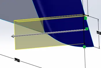
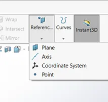
8. Reference Geometry: Reference geometry defines the shape or form of a surface or a solid. Reference geometry includes items such as planes, axes, coordinate systems, and points. You can use reference geometry in the creation of several kinds of features. For example:
- Planes are used in lofts and sweeps.
- An axis is used in a circular pattern.
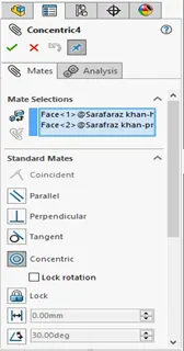
9.Mate: Mates create geometric relationships between assembly components. As you add mates, you define the allowable directions of linear or rotational motion of the components. You can move a component within its degrees of freedom, visualizing the assembly's behavior.
Some examples include:
- A coincident mate forces two planar faces to become coplanar. The faces can move along one another but cannot be pulled apart.
- A concentric mate forces two cylindrical faces to become concentric. The faces can move along the common axis but cannot be moved away from this axis.
Mates are solved together as a system. The order in which you add mates does not matter; all mates are solved at the same time. You can suppress mates just as you can suppress features.
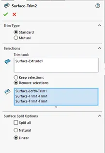
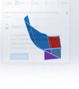
10. Surface trim:-we can use a surface trim, plane, or sketch as a trim tool to trim intersecting surfaces. we can also use a surface in conjunction with additional surfaces, as mutual trim tools trim surfaces using surfaces, sketch entities, curves, planes, and so on.
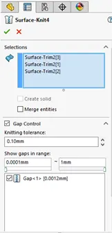
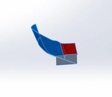
11. Knit surface:- use the knit surface tool to combine two or more faces and surfaces into one knit surface to absorb the surface bodies you used to create them. Create a solid body when the knit surfaces from a closed volume, or leave it as a surface body. Select merge entities to merge faces with the same underlying geometry.
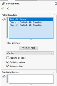
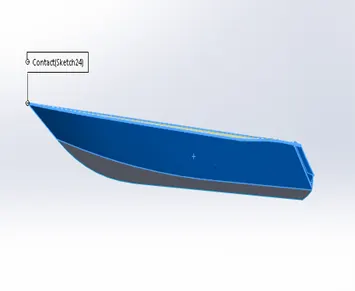
12. Filled surface:-the filled surface features construct a surface patch with any number of sides, within a boundary defined by existing model edges, sketches, or curves, including composite curves. We can use this feature to construct a surface to fill a gap in a model.
- Blueprint setup
following steps need to get the setup:-
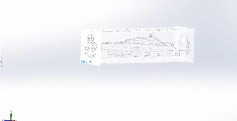
Go to tools then sketch a picture and browse the picture location file and click ok. Then give properties data to get the exact setup.
It is important to use 2d sketches which are made prior to modeling as it helps us to analyze and set up complex shapes. These 2d sketches also called blueprints acts as a reference to understand any given model clearly and easily. The blueprints used for the yacht as shown below.
2.Propeller:-
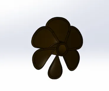
Its rotary motion through the air creates a difference in pressure between the front and back surfaces of its blades. It provides thrust so that the yacht moves easily. propeller looks like a fan, it is placed such that it is submerged inside water. The propeller is the main component for the navigation of a yacht, it receives power from the engine it helps the yacht to move forward or backward by pushing the water in opposite direction, for instance, if the ship is moving forward the propeller pushes the water backward and vice versa.
Features used:-
- Revolve
- Plane
- Loft extrude
- Fillet
- Cut extrude
- Circular pattern
3.Radar
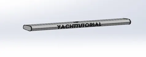
It is used to detect the object’s position, signals, etc. relative to the position of the yacht. It is mated with a part called radar mast and placed on the topmost part of the yacht. it is modeled only in solid modeling.it is an asymmetric model so the other half is mirrored. The name is engraved using text and cut extrude (offset from the surface) commands.
Features used:-
- Boss extrude
- Fillet
- Cut extrude
- Sketch pattern
- Mirror
- Split line
4.Hull
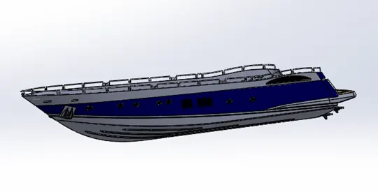
It is the watertight enclosure of the ship, which protects the goods carrying area, machinery, and accommodation spaces of the ship from the weather, flooding, and structural damage is the base of the yacht and it is an asymmetric model. Therefore it is enough to model one half and the other half could be mirrored.
First, the hull is developed in surface modeling. Then after completing the model by the surface it is converted to solid and proceeded with the solid modeling. This is because the hull consists of the surface with complex curvature, therefore it is wise to model with the surface then converted it as a solid.
Features used:-
- Surface loft
- Surface trim
- Surface extrude
- Surface knit
- Surface fill
- Shell
- Boss extrude
- Cut extrude
- Chamfer
- Fillet
- Plane
- 3d sketch
- Sweep
- Revolve
- Linear pattern
- Mirror
- Delete face
5.Garage door
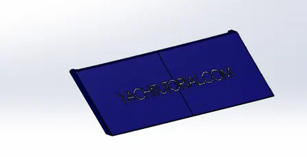
The part is modeled in a solid model which was saved when a split command was used during modeling hull. The part is retrieved and is used for the construction of the garage door. It is an asymmetric model, therefore the other half is mirrored. The name is engraved using text and cut extrude (offset from the surface) commands.
Features used:-
- Cut extrude
- Shell
- Mirror
- Fillet
6.Front seat
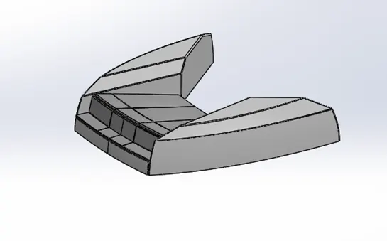
It is used for rest. It is also an important part of the superstructure.
Features used:-
- Surface sweep
- Surface extrude
- Surface trim
- Surface fill
- Surface knit
- Chamfer
- Revolve
- Cut extrude
- Fillet
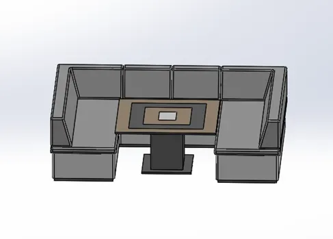
7.Middle seat
It is used for rest. It is also an important part of the superstructure.
Features used:-
- boss extrude
- plane
- chamfer
- fillet
- mirror
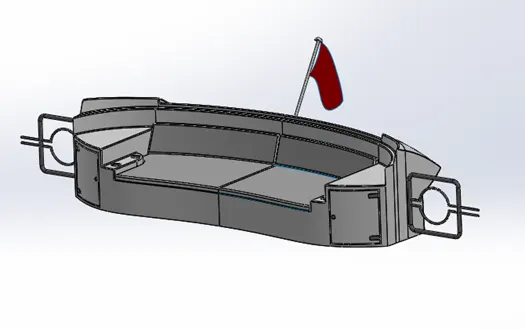
8.Rear seat
It is used for rest. It is also an important part of the superstructure.
Features used:-
- Surface sweep
- Surface offset
- Surface trim
- Ruled surface
- Surface knit
- Surface loft
- Surface extend
- Boss extrude
- Cut extrude
- Chamfer
- Fillet
- Mirror
9.Superstructure
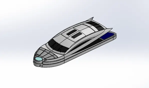
A superstructure is an upward extension of the yacht. It is like a head & gives a pretty good look and is mounted over the hull. By the base isolation, the whole yacht can be protected from severe models therefore it is enough to model one half so that the other half could be mirrored. It is modeled in a way the same as hull, the model is started imported from the hull as reference. The desired surfaces are modeled and the surface model is converted into solid and proceeded with solid modeling.
Features used:-
- Surface extrude
- Surface trim
- Cut extrude
- Knit surface
- Chamfer
- Fillet
- Mirror
- Ruled surface
10.Radar mast
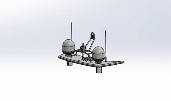
It is the complete assembly of the radar system which protects from harmful things.it is a device that comes along with radar it is used to control the position and direction of the radar.it also processes the signals which are sent and received. It is modeled based on the deck surface imported from the superstructure.
Features used:-
- Revolve
- Boss extrude
- Sweep
- Fillet
- Mirror
11.Assembly of yacht
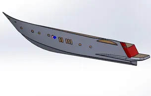
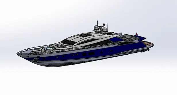
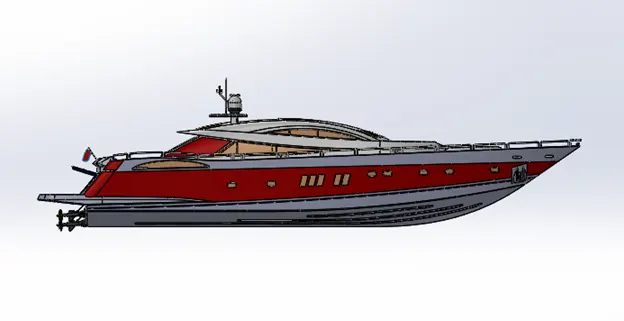
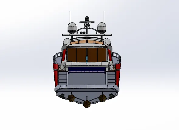
In the assembly part, all individual parts are inserted into assembly tools of Solidworks. Fix one of the components into the work base. Proved mates and relation remaining part to the fixed one concerning line, vertex & planes. after modeling the individual parts the files are imported into the assembly area in order and are mated with required constraints.
The commonly used constrains are coincident, offset, concentricity etc.
12.Rendering
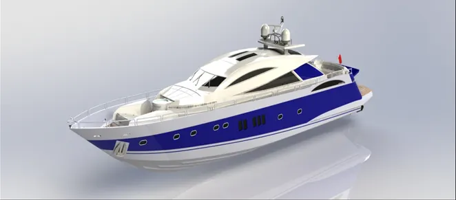
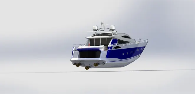
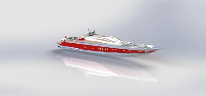
It is a very important part because of different materials, colors, etc to be applied to assembly one. Here, the product is to be seen under environmental conditions with different views. It gives a realistic view of the model relative to the environment. before proceeding with rendering the model should be adjusted such that it looks realistic. cameras are added and are adjusted to get the desired view. Edit scene command is used to get the required environment and options.
Rendering is done, and the images are shown below.
Conclusion
- The sunseeker predator yacht had completed.
- This challenge is very interesting and a lot of tools are covered in this challenge helps me to improve my knowledge in Solidworks.
- The realistic image is created using solidworks.