Advanced Sheet Metal Design Using NX Cad Challenge_7_ Metal bracket-II
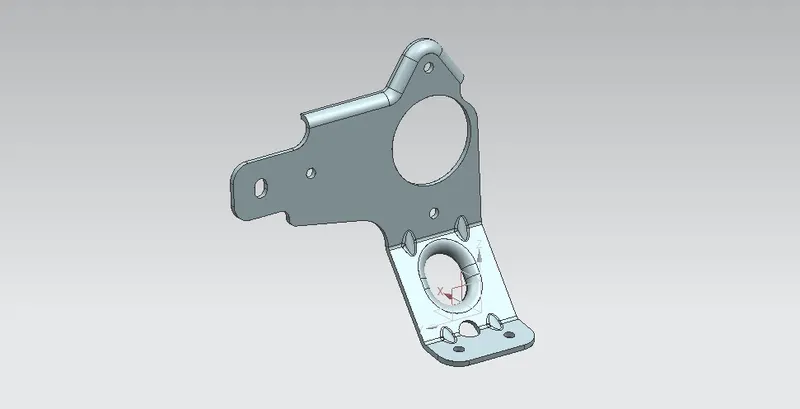
TITLE: METAL BRACKET Ⅱ DESIGNING USING SIEMENS NX.
OBJECTIVE:
- To design metal bracket Ⅱ using NX sheet metal.
- To Improve sheet metal designing skills.
INTRODUCTION:
Sheet metal design is governed by the premise that the raw material used to form a sheet metal part is of common stock and uniform thickness. When metal is hot rolled into flat sheet which ranges from 0.5mm to 6mm thickness uniformly across the length termed as sheet metal. Sheetmetal is the most versatile material in the manufacturing industry. It ranges in thickness from wispy leaf to heavy plate. Its uses expand across many different industries including transportation, aerospace, electronics, machinery and many more. Siemens Nx considers the fabrication method needed for manufacturing. While designing as I created contour flange, beads, hole etc. after designing it is showed in flat pattern feature for manufacturing consideration. In this project we are dealing with metal bracket Ⅱ design using Siemens Nx.
DESIGN METHODOLOGY:
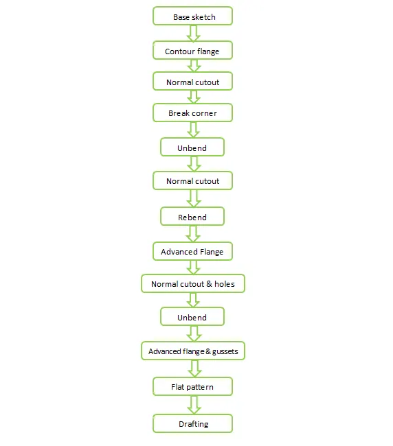
The metal bracket created for this project consist of various features like contour flange, bead, hole, normal cutout, break corner etc. while designing We have to keep eye on the base sketch dimmensions and relation between sketches. simple and easy design methodology is followed in industrial manner. The design methodology used for this project is depicted below.
DISCRIPTION:
Sketch:
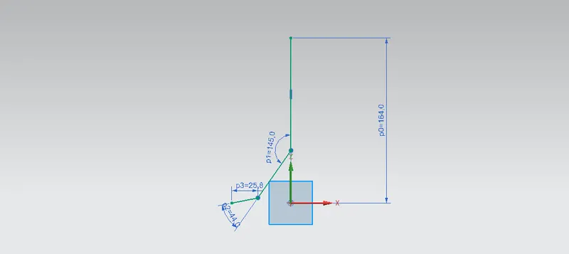
Sketches are the foundation of any design model. For creating most of the sheet metal surface, first we have to create a base sketch. For designing of metal bracket, firstly I created a base sketch for contour flange. other than contour flange I created a sketch on different face and planes for normal cutout and also for other further designing.
Contour flange:
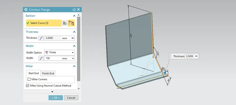
A contour flange can be used to create a base feature from a sketch, or it can be used to quickly construct flange geometry along existing thickness edges of a sheet metal part. For this metal bracket design I creates a contour flange having a thickness of 3mm and width of 158mm.
Normal cutout:
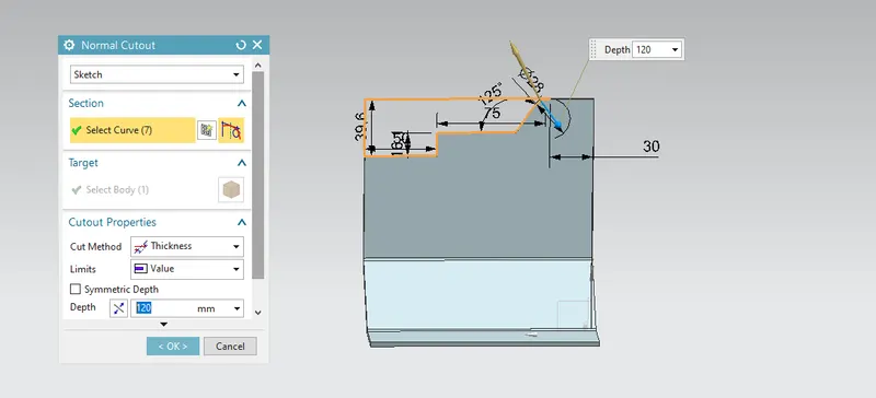
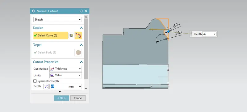
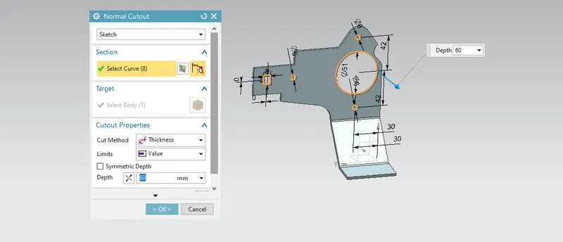
Normal cutout feature is used to remove material from the part by creating a desired sketch on to the face or part. For this metal bracket design I creates a different shapes of sketches to remove the material.
Break Corner:
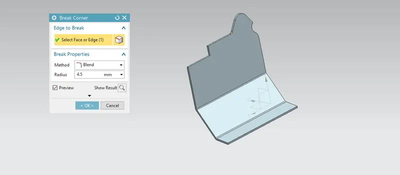
Break corner feature is used to smoothen the corners by giving chamfer or fillet to the sheet metal corners. Break corner is used to prevent stress concentration and fracture braking while manufacturing. In this metal bracket design I used break corner command.
Normal cutout:
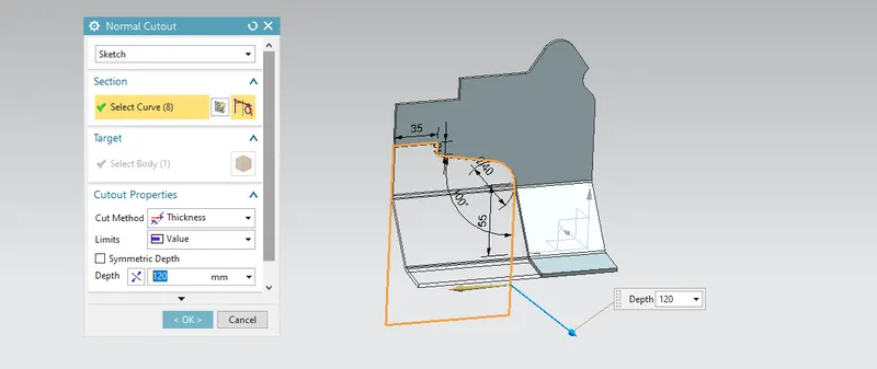
After break corner I creates a desired sketch on face of part and again used normal cutout command 2 times to remove the material.
Unbend:
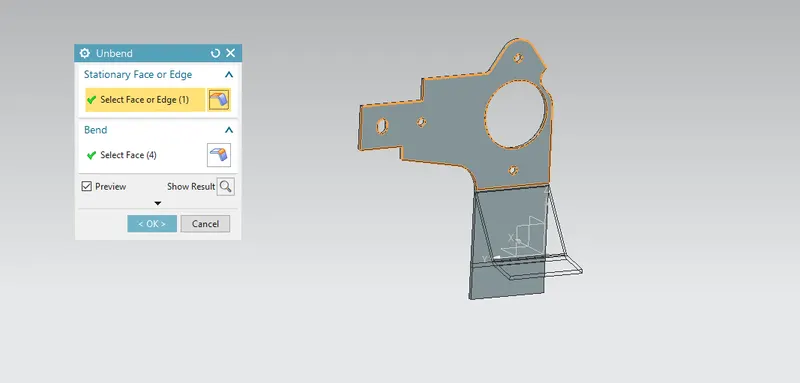
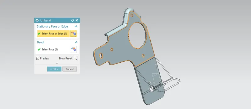
Unbend is the most likely used feature in NX. In industry while manufacturing we have to first perform certain operation on unbended sheet metal part and then we have to bend it for easy and accurate manufacturing. Thus similar activity we followed in the siemens Nx. In this metal bracket design I used this command by selecting stationary face and bends.
Normal cutout:
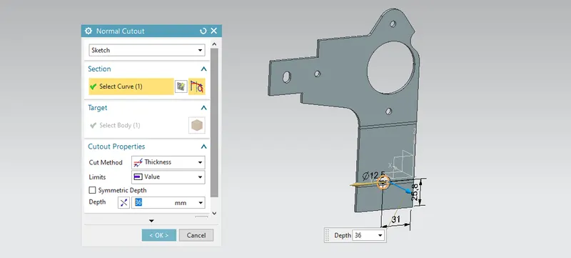
Normal cutout feature is used to remove material from the part by creating a desired sketch on to the face or part. For this metal bracket design I created a different shapes of sketches to remove the material. First, I created circular sketch on the lower front face having diameter of 12.5 mm.
Rebend:
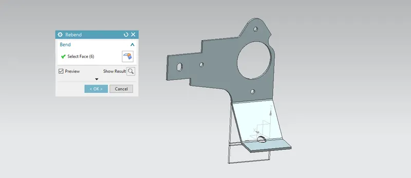
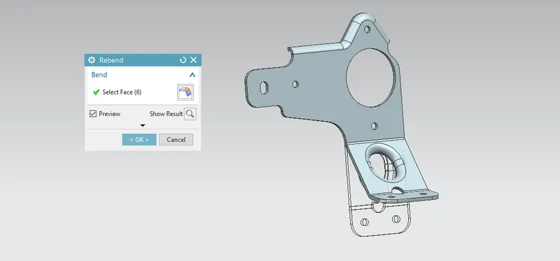
Rebend feature is used to restore the unbend feature to its previous bend state along with any features added after the unbended feature. While performing rebend we have to keep eye on selecting bends in order they were unbended.
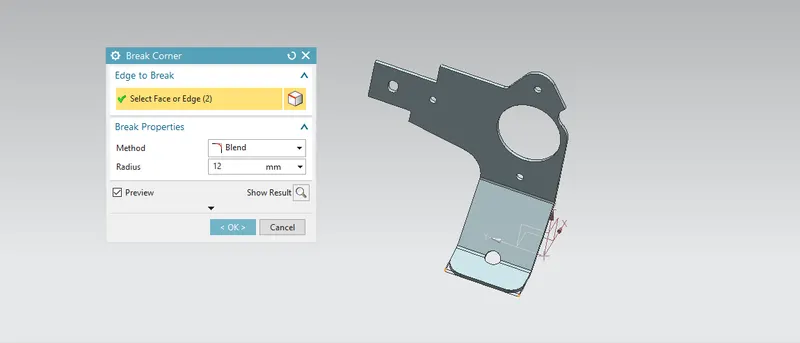
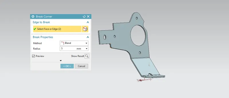
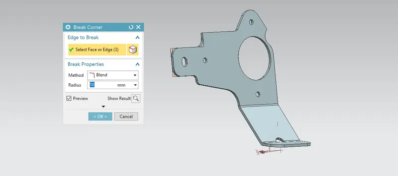
Break corner:
After rebend different corner having sharp edges were smoothen by using break corner feature repetitively with appropriate radius.
Advanced flange:
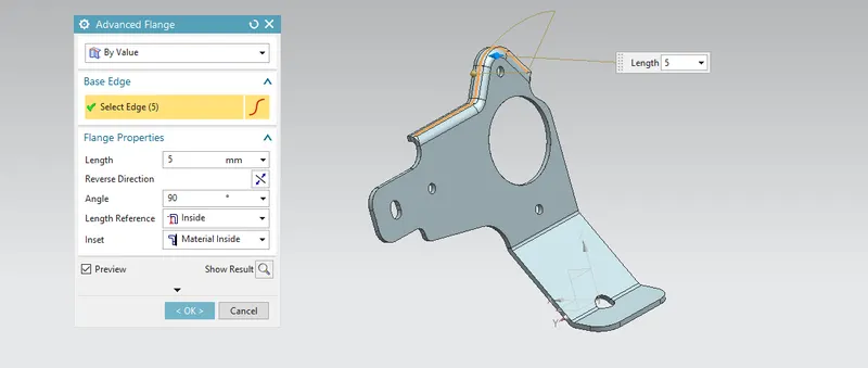
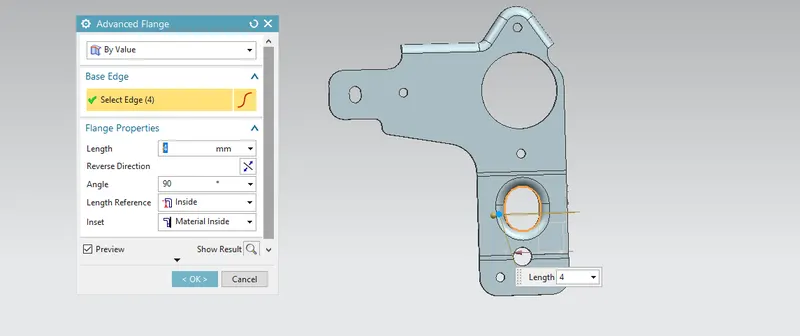
Advanced flange adds flange along the edge using the reference face or bend angle. The edge and reference face can be curved. Flange properties namely length, angle, length reference and insert type are defined along with bend parameters, end limits and relief.
Unbend:
For doing further operations like hole, normal cutout and advanced flange sheet metal bracket was unbended.
Hole:
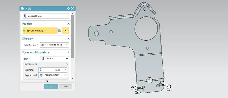
Hole feature is used to generate hole with definite parameter on sheet metal in siemens NX. We can create different types of holes, for this metal bracket design I created general hole. Fistly, I creates a sketch of 2 points then creates a hole of 6mm diameter.
Normal cutout:
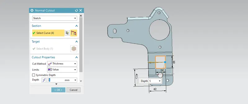
Again normal cutout feature was used to cut the rectangular shape of sheet metal.
Advanced flange:
Advanced flange was used for previously created rectangular cutout as shown below.
Rebend:
Rebend feature is used to restore the unbend feature to its previous bend state along with any features added after the unbended feature. While performing rebend we have to keep eye on selecting bends in order they were unbended.
Gussets:
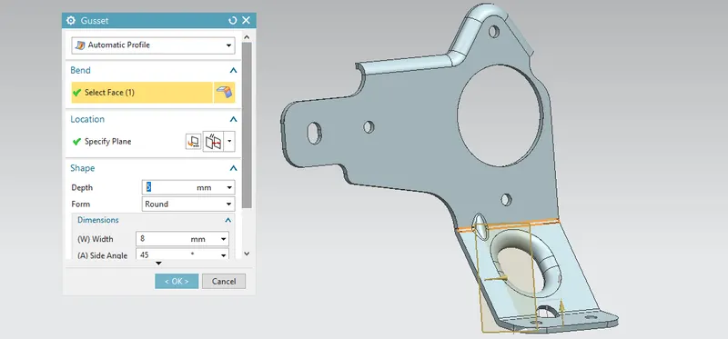
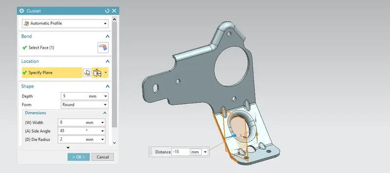
gussets are basically supporting features. The main function of the gussets is to provide stiffening and strength to the part. these feature applied at the bends. For this bracket, four rounded gussets are applied on the bends as shown below.
Flat pattern:
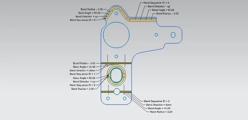
Flat pattern is the representation of the entire sheet metal component in the 2D form with all the bends, beads, holes and additional features in the form of lines or edges. The flat pattern ensures the ability to cut the sheet metal out of the raw sheet metal plate. It removes the possible errors such as interface or collision within the same component.
Drafting:
After the modelling, the manufacturing requirement of the component a technical 2D drawing of the component with accurate dimensions or scales is denoted, for achieving this we are using the command draft.
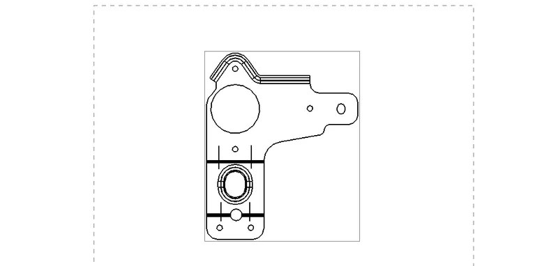
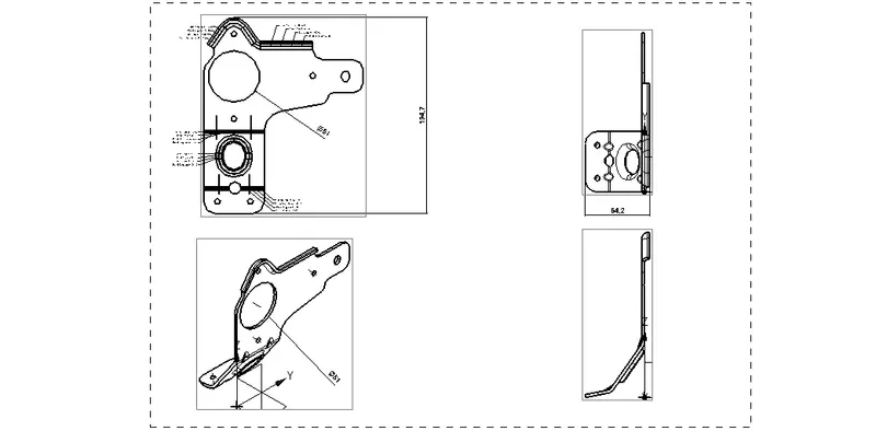
Different views of Metal Bracket Ⅱ :
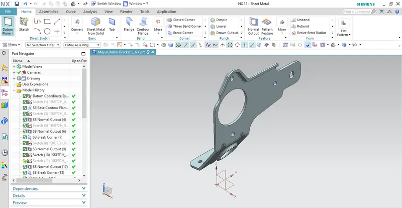
Isometric View:
Front View:
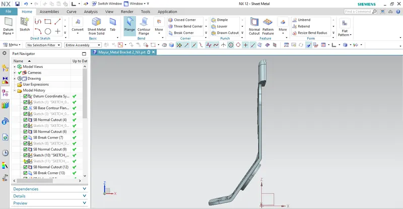
Top View:
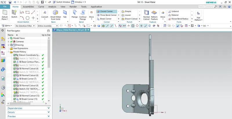
Side View:
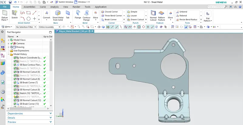
Conclusion:
- Succesfully learned to design a sheet metal bracket Ⅱ in industrial manner using siemens NX.
- Improves sheet metal designing skills.