Advanced Sheet Metal Design Using NX Cad Challenge_7_ Metal bracket-II
A Project Report
on
Advanced Sheet Metal Design Using NX Cad Challenge_7_ Metal bracket-II
Done by
PRAKASH
TABLE OF CONTENTS
|
S.NO |
TITLE |
|
1. |
OBJECTIVE |
|
2. |
INTRODUCTION |
|
3. |
DESIGN METHODOLOGY |
|
4. |
DESCRIPTION |
|
5. |
PROCEDURE |
|
6. |
SCREENSHOTS |
|
7. |
DETAILED DRAWING SHEET IMAGE |
|
8. |
CONCLUSION |
1. OBJECTIVE:
To design a Bracket using Advanced Siemens NX Sheet Metal.
2. INTRODUCTION:
NX™ software, the digital product development solution from Siemens, includes a set of state-of-the art tools for designing sheet metal components. Using familiar terminology and workflows, NX Sheet Metal Design provides the design professional with a complete set of tools to efficiently create and manage sheet metal parts based on the knowledge of material properties and manufacturing processes. NX Sheet Metal Design tools incorporate material and bending information, enabling the model to represent both the formed component and flattened blank shapes.
The sheet metal design tools within NX allow companies to apply defaults – based on both industry and company best practices – to the values used in the creation of sheet metal parts. For example, bend radii and neutral factor values can be set to commonly used values to encourage re-use and save design time. Folded and unfolded views of sheet metal components can be used in both the 3D environment as well as downstream in 2D documentation and for manufacturing.
DESCRIPTION:
- SKETCH TOOLS:
Sketching is the process of creating 2D drawing before developing it in 3D. In Siemens NX Sheet Metal, there are a plenty of options and has various tools for creating a 2D sketch. In that a few tools which are used for drawing the casing is discussed below.
- STRAIGHT-LINE:
The straight line is one of the sketch tools which is used to draw a straight line. It creates lines with constraint inferencing.
- ARC:
It creates an arc through three points or by specifying its centers and endpoints.
- CIRCLE:
It creates a circle through three points or by specifying its centers and diameters.
- RECTANGLE:
Creates a rectangle using any of three different methods.
- POINT:
It is used to create sketch points in a 2D plane.
- CONTOUR FLANGE:
It is used to create a base feature by extending a sketch along a vector or adds material by sweeping a sketch along an edge or chain of edges.
- BREAK CORNER:
It is used to create rounds or chamfers around sharp corners of a tab or flange
- NORMAL CUTOUT:
It is used to create cut material by projecting a sketch onto the model and then cutting perpendicular to the faces intersected by the projection.
- UNBEND:
It is used to flatten a bend and the material adjacent to the bend.
- REBEND
It is used to restore an unbend feature to its previous bend state, along with any features added after the unbend feature.
- HOLES:
It is used to add a hole to one or more solid bodies in a part or assembly with options for counterbored, countersunk, and threaded.
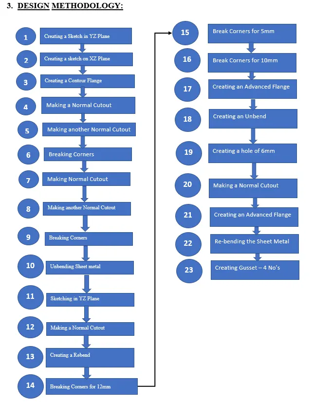
5. PROCEDURE
CREATING A SKETCH IN YZ PLANE:
- After opening Siemens NX 12 – Click on “New” Button - Select Sheet Metal – In the pop-up window select “Sheet Metal” – Click ok.
- In the Sheet Metal Window – Click on “Sketch” and select XY Plane - Click ok.
- Draw the sketch as per the requirement.
CREATING A SKETCH IN XZ PLANE:
- Click on the ‘sketch’ button – select XZ plane – draw the sketch as per the requirement.
CREATING A CONTOUR FLANGE:
- Click on the button titled “Contour Flange” available along the Ribbon Bar.
- Now create a contour flange for the sketch drawn on XZ plane.
MAKING A NORMAL CUTOUT:
- Click on the button titled “Normal Cutout” available along the ribbon bar.
- Select the sketch drawn in the previous step – change the direction of the arrows so that the cut is created on the necessary area – Click ok.
MAKING ANOTHER NORMAL CUTOUT:
- Create another set of normal cutout using the sketch drawn in step one.
BREAKING CORNERS:
- Now create fillets using the command “Break Corners”
MAKING NORMAL CUTOUT:
- Create another normal cut out as per the design requirement.
MAKING ANOTHER NORMAL CUTOUT:
- Create another normal cut out as per the design requirement.
BREAKING CORNERS:
- Create fillets as per the design requirement using the command “Break corners”
UNBENDING SHEET METAL:
- Now create an unbend using the command “Unbend”
SKETCHING IN YZ PLANE:
- Create another sketch in YZ plane.
MAKING A NORMAL CUTOUT:
- Create a normal cutout for the sketch drawn in YZ plane.
CREATING A RE-BEND:
- Create a Rebend using the command “Rebend”
BREAKING CORNERS FOR 12mm:
- Create Fillets for 12mm by using the command called “Break Corners” – and then select the required corners.
BREAKING CORNERS FOR 5mm:
- Create Fillets for 5mm by using the command called “Break Corners” – and then select the required corners.
BREAKING CORNERS FOR 10mm:
- Create Fillets for 10mm by using the command called “Break Corners” – and then select the required corners.
CREATING AN ADVANCED FLANGE:
- Create an advanced flange as per the design requirement.
CREATING AN UNBEND:
- Create an unbend by using the command called “Unbend”.
CREATING A HOLE OF 6mm:
- Create a hole of 6mm using the command called “Hole”.
MAKING A NORMAL CUTOUT:
- Create a normal cut out as per the design requirement.
CREATING AN ADVANCED FLANGE:
- Create an advanced flange as per the design requirement.
RE-BENDING THE SHEET METAL:
- Rebend the sheet metal to its previous shape by using the command called “Rebend”
CREATING GUSSETS – 4NO’S
- Create Gussets – 4 nos’ by using the command called as Gussets.
6. SCREENSHOTS
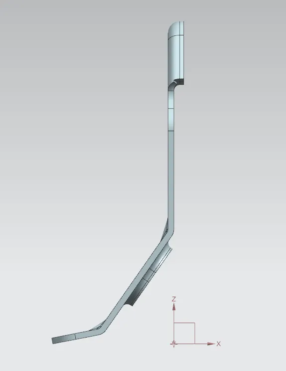
Front View
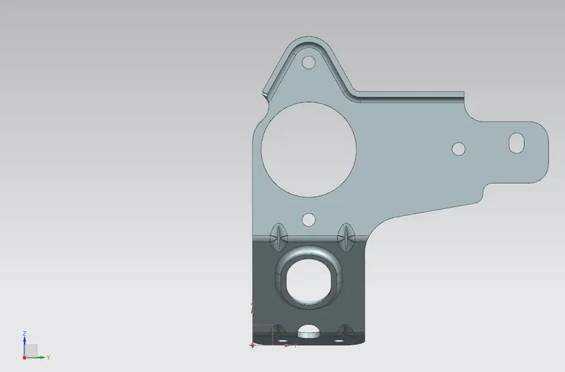
Right Side View
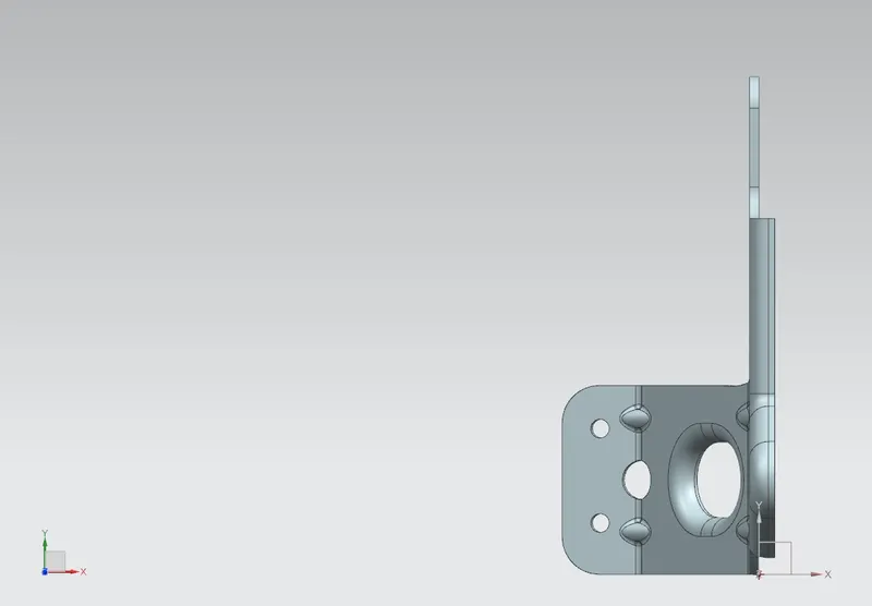
Top View
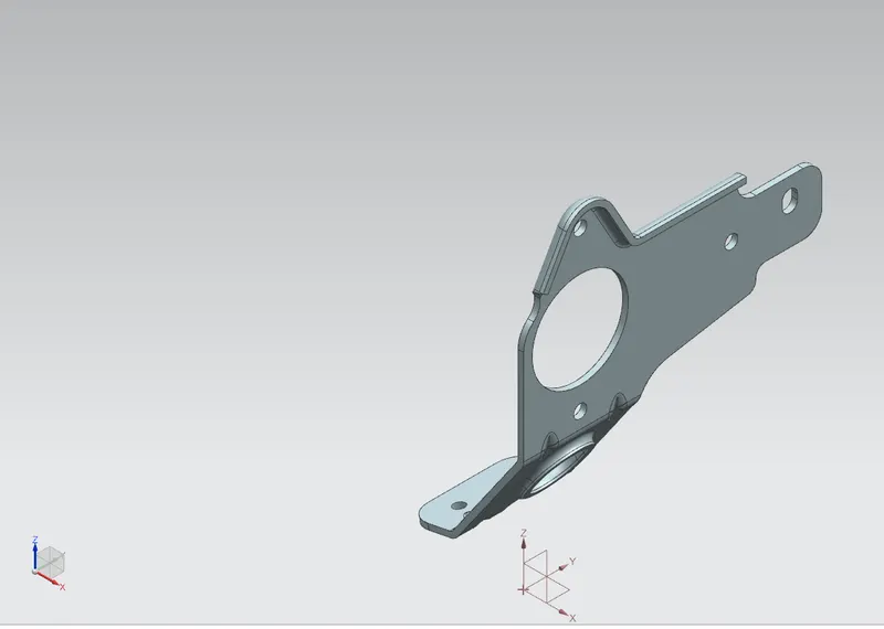
Isometric View
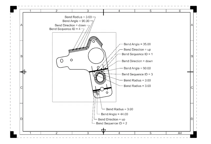
DRAFTED FLAT PATTERN IMAGE OF THE BRACKET:
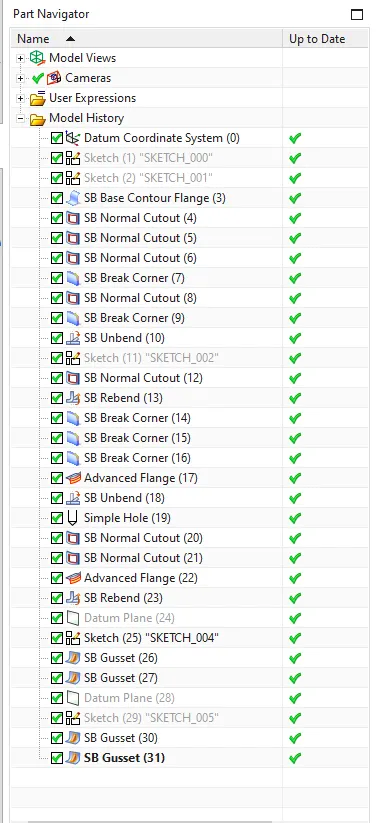
FEATURE TREE
7. CONCLUSION:
Thus, the Metal Bracket has been designed using Siemens NX Sheet Metal and various features had been executed successfully. A Drafted image of the flat pattern is also obtained.