Advanced Sheet Metal Design Using NX Cad Challenge_1_Casing Design
A Project Report
on
DESIGNING A CASING USING SIEMENS NX SHEET METAL SOFTWARE
Work Carried out by
PRAKASH.R
TABLE OF CONTENTS
|
S.NO |
TITLE |
|
1. |
OBJECTIVE |
|
2. |
INTRODUCTION |
|
3. |
DESIGN METHODOLOGY |
|
4. |
DESCRIPTION |
|
5. |
PROCEDURE |
|
6. |
SCREENSHOTS |
|
7. |
DETAILED DRAWING SHEET IMAGE |
|
8. |
CONCLUSION |
- OBJECTIVE:
- To design a casing using Siemens NX Sheet Metal.
- INTRODUCTION:
NX™ software, the digital product development solution from Siemens, includes a set of state-of-the-art tools for designing sheet metal components. Using familiar terminology and workflows, NX Sheet Metal Design provides the design professional with a complete set of tools to efficiently create and manage sheet metal parts based on the knowledge of material properties and manufacturing processes. NX Sheet Metal Design tools incorporate material and bending information, enabling the model to represent both the formed component and flattened blank shapes.
The sheet metal design tools within NX allow companies to apply defaults – based on both industry and company best practices – to the values used in the creation of sheet metal parts. For example, bend radii and neutral factor values can be set to commonly used values to encourage re-use and save design time. Folded and unfolded views of sheet metal components can be used in both the 3D environment as well as downstream in 2D documentation and for manufacturing.
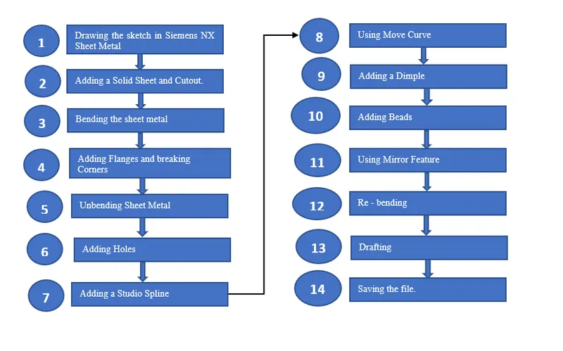
- DESIGN METHODOLOGY:
4. DESCRIPTION:
4.1. SKETCH TOOLS:
Sketching is the process of creating a 2D drawing before developing it in 3D. In Siemens NX Sheet Metal, there are plenty of options and has various tools for creating a 2D sketch. In that, a few tools that are used for drawing the casing is discussed below.
4.1.1. STRAIGHT LINE:
The straight line is one of the sketch tools which is used to draw a straight line. It creates lines with constraint inferencing.
4.1.2. ARC:
It creates an arc through three points or by specifying its centers and endpoints.
4.1.3. CIRCLE:
It creates a circle through three points or by specifying its centers and diameters.
4.1.4. RECTANGLE:
Creates a rectangle using any of three different methods.
4.1.5. POINT:
It is used to create sketch points in a 2D plane.
4.1.6. PROFILE:
Creates a series of connected lines and /or arcs in string mode: that is, the end of the last curve becomes the beginning of the next curve.
4.1.7. MIRROR CURVE:
This tool is used to create a mirror pattern of a chain of curves that lie on the sketch plane.
4.1.8. ELLIPSE:
It is used to create ellipses by using center points and dimensions.
4.1.9. INTERSECTION CURVE:
It is used to create an intersection curve between faces and the sketch plane
4.1.10. STUDIO SPLINE:
It dynamically creates and edits splines by dragging defining points or poles, and assigning slope or curvature constraints at defining points.
4.1.11. MOVE CURVE:
It is used to move a set of curves and adjust adjacent curves to accommodate.
4.13. TAB:
It is used to create a base feature by extruding a sketch along a vector by a thickness value or adds material to a planar face. Additional planar selections can be added to generate bends as part of the base feature.
4.14. FLANGE:
It is used to add a flat flange at an angle to a planar face and adds a bend between the two.
4.15. BEND
It is used to modify a model by bending material on one side of a sketch line, adding a bend between the two sides.
4.16. BREAK CORNER:
It is used to create rounds or chamfers around sharp corners of a tab or flange
4.17. DIMPLE:
It is used to lift an area of the model inside a sketch that simulates a stamping tool.
4.18. NORMAL CUTOUT:
It is used to create cut material by projecting a sketch onto the model and then cutting perpendicular to the faces intersected by the projection.
4.19. UNBEND:
It is used to flatten a bend and the material adjacent to the bend.
FLAT PATTERN:
It is used to create a flat pattern from the formed sheet metal part.
REBEND
It is used to restore an unbend feature to its previous bend state, along with any features added after the unbend feature.
5. PROCEDURE:
5.1. DRAWING THE SKETCH IN SIEMENS NX SHEET METAL:
- After opening Siemens NX 12 – Click on “New” Button - Select Sheet Metal – In the pop-up window select “Sheet Metal” – Click ok.
- In the Sheet Metal Window – Click on “Sketch” and select XY Plane.
- Click on “Rectangle Icon” located under “Direct Sketch Ribbon Bar” and draw a rectangle with the center at origin and having a length of 60mm in the X direction and 50mm width along the Y direction.
- Exit the sketch mode.
- Change the design parameters by going to Menu – Preferences – Sheet Metal and then in the “Sheet Metal Preferences” dialog box set all of the four Global Parameters to 1mm.
5.2. ADDING A SOLID SHEET AND CUTOUT:
- Click in “Tab” button to create a rectangular sheet metal of 1mm thickness.
- Click on the “New Sketch” button and click the top face of the sheet metal which is parallel to the XY plane.
- Create a new sketch on this face by drawing a rectangle that is symmetric with respect to the X-axis and is coincident with the left edge of the rectangular sheet metal.
- This rectangle is 5mm wide and 40mm long.
- The mid-point of the rectangle will be collinear with the origin.
- Exit the sketch mode and then click on Cutout Button.
- This cutout command will remove the rectangular section which is drawn using the sketch tool.
5.3. BENDING THE SHEET METAL:
- Create another sketch on the top face of the sheet metal by clicking on the sketch button and then selecting the top face of the sheet metal.
- Draw two symmetric horizontal lines with respect to X-axis.
- Make sure to locate the upper horizontal line at a distance of 10mm from the upper left corner of the sheet metal.
- Exit the sketch mode and then click on the Bend button which is located under “More” drop-down list box situated under a group name “Bend” on the ribbon bar.
- In the bend dialog box, select any one line as the bend line and enter an angle of 90 degrees.
- Repeat the same procedure for the other symmetric line also.
- If required, use the reverse side option for obtaining the exact result.
5.4. ADDING FLANGES AND BREAKING CORNERS:
- Click on the flange button located under the group titled “Bend” on the ribbon bar.
- Change the length to 5mm and apply flange on the edge of the sheet metal then click ok.
- Apply the same flange to the corresponding symmetric edge of the sheet metal
- Apply the flange of the same size to the bottom ends of the bend in the sheet metal but it should be in opposite direction.
- Click on the “Break Corners” located under the group titled “Corner” along the ribbon bar.
- In the break corner dialog box, use the Blend method with a radius of 1mm.
- Click and drag the cursor such that the entire part is selected and then click ok.
- This will apply the break corners to all the sharp edges.
5.5. UNBENDING SHEET METAL:
- Now click on the “Unbend button” located under the group titled “Form” towards the end of the ribbon bar.
- In the unbend dialog box, select the Stationary Face, which is a large-sized horizontal face of the sheet metal.
- Now select the adjacent face as one of its bend faces.
- This feature will unbend all the bend sections of the part.
5.6. ADDING HOLES:
- Create a sketch on the flat larger plane or else select the bottom-left bend section of the part and create a sketch in that area.
- In the lower-left part of the sheet metal draw a line whose ends are located at the middle of the bend section.
- Click on the “Point” Creation button located under the Direct Sketch group along the ribbon bar.
- Draw this point at the center of this line.
- Finally, from the point create a symmetric point with respect to the x-axis of the Datum Coordinate System.
- Similarly, create two other symmetric points (with respect to the x-axis of the Datum Coordinate System) in the upper part of the sheet metal.
- The first point will be located in the middle of the line.
- The ends of this line will themselves be located in the middle of segments of the sheet metal.
- Now click on the Hole button located under “More” drop-down list box situated under a group name “Feature” on the ribbon bar.
- In the hole dialog box, use Screw clearance Hole as Type, with a M2 Screw size and a H13 Fit.
- Set the Depth Limit option to Through Body.
- Create four holes centered on the four previously defined points.
5.7. ADDING A STUDIO SPLINE:
- In the XY Plane, create the sketch of the required shape where each half side is 5mm in length, and the sketch is centered at the origin (0,0,0).
- Click on the “Spline Studio” button, and in the “Studio Spline” dialog box, set the Type field as “By Poles” – Check the “Closed” Option.
- Select one by one all the 16 points of the sketch in a clockwise or anticlockwise direction.
- Click ok to validate the new spline curve creation.
5.8. USING MOVE CURVE:
- Click on the “Move Curve Button.
- In the “Move Curve Dialog box” select the spline curve which was just drawn.
- Set the Motion option of the Transform field to Angle.
- Specify the origin (0,0,0) as the axis point.
- Finally, enter the angle of 45 degrees and click ok to validate.
5.9. ADDING A DIMPLE:
- Click on the Dimple button located under the group titled “Punch” along the Ribbon Bar.
- Now select the spline curve.
- Set the “Depth” Option to 1mm and Side Walls to Material Inside.
- Expand the Dialog box by left clicking on the inverted little blue colored triangle titled “Rounding” field.
- Set all the parameters of the Rounding field to 1mm.
- Click ok to validate the dimple.
5.10. ADDING BEADS:
- Again, start creating a sketch on the XY plane.
- Draw a circle of diameter 5mm diagonally across the dimple created.
- The position of the circle should be at 8mm in both vertical and horizontal direction from the top corner of the rectangular cutout.
- Now, click on the BEAD button located under the group titled “Punch” along the Ribbon Bar.
- In the Bead dialog box, select the circle which is just drawn and set the Depth and Radius option to 1mm, and the Cross-Section to Circular.
- Expand the Rounding Field and in that fieldset the Die Radius to 1mm.
- Then click on ok to validate the results thus obtained.
5.11. USING MIRROR FEATURE:
- Click on “Mirror Feature” button, under the More button of the Feature field.
- Select the bead and its corresponding sketch as the Feature to Mirror.
- Select the YZ plane as the mirror plane and click Apply to validate the results.
- Then, select the two beads and their corresponding sketches then redo a feature mirror by choosing XZ plane this time.
5.12. RE - BENDING:
- Click on the Rebend button located under the group titled “Form” along the Ribbon bar.
- Rebend the faces by selecting them in the reverse order in which they were bend or else just simply drag and select the entire part which would result in complete re - bending of the part.
5.13. DRAFTING:
- Click on the “Flat Pattern” button located under the Flat Pattern Menu.
- Select the central flat face of the sheet metal and click ok.
- This will create a flattened version of the sheet metal.
- If an information dialog box opens, just click ok.
- For the moment, the flattened version is not visible. To make it visible, go in the Part Navigator and expand the Model View Tree.
- Double click on the object named FLAT – PATTERN#1.
- Create a new drafting file by going into the “Application” available on the Tabs and then click on “Drafting” button located along the Ribbon bar.
- In the pop-up window titled “Sheet” select the bullet as “Standard Size” under the dialog box “Size” and also select “A4 – 210 x 297” as size and the ratio as “2:1”- then click ok to validate the results.
- After creating the A4 Sheet, click on “Base View” button available as a 3rd button along the ribbon bar inside the Drafting window.
- In the “Base View” Dialog box, select in the option ‘Model View to use’ as “FLAT – PATTERN#1” and then set the scale to 2:1.
- Click ok to validate the results.
5.14. SAVING THE FILE:
- Save the file by going into File – Save – Save as – in the window that pops up browse through it to the folder where the part is needed to be saved – select the name mentioned against File name and then change to “Challenge 1” – then click on ok to save the file.
6. SCREENSHOTS
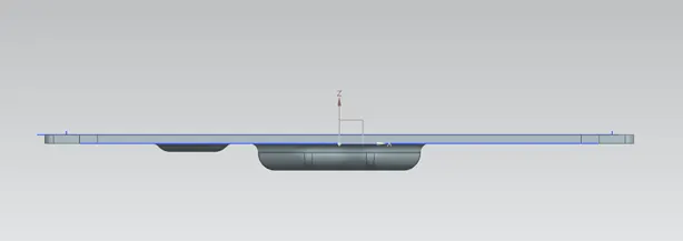
Fig 1 – Casing Front View
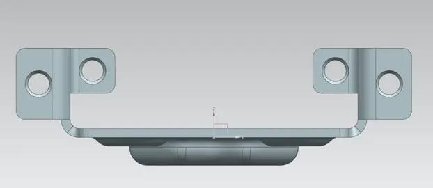
Fig 2 – Casing Right Side View
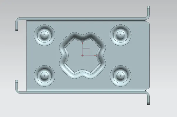
Fig 3 – Casing Top View
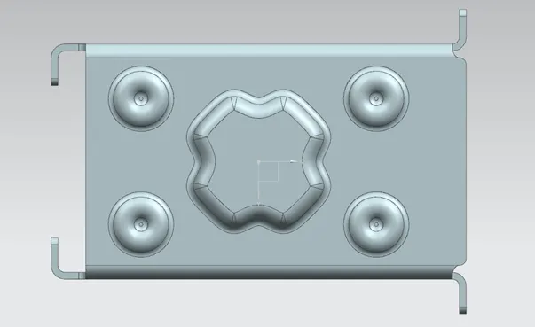
Fig 4 – Casing Bottom View
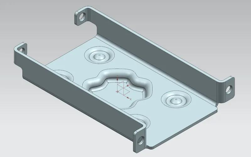
Fig 5 – Casing Isometric View
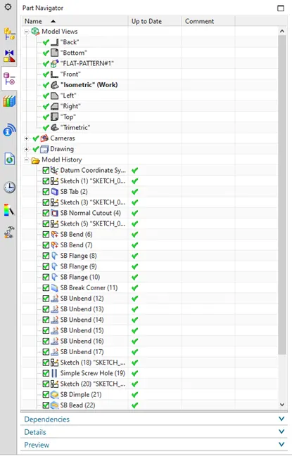
Fig 6 – Casing Design: Feature Tree 1
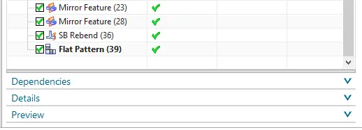
Fig 7 – Casing Design: Feature Tree 2
7. DRAFTED IMAGE OF THE CASING:
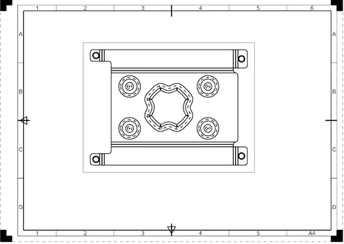
Fig 8 – Drafted Image of Casing
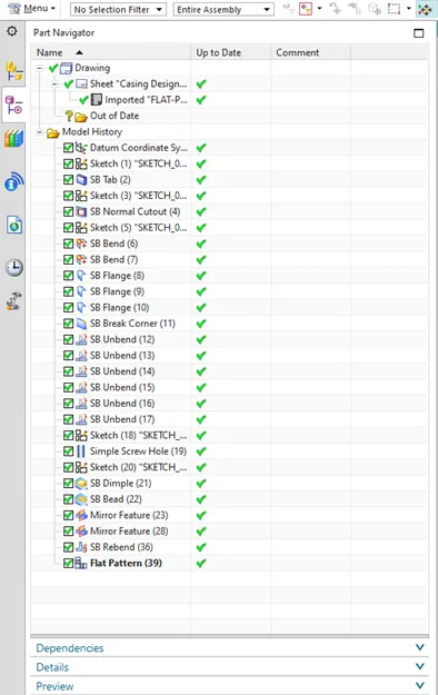
Fig 9 – Feature Tree for Drafted Sheet Metal
8. CONCLUSION
Thus, the objective of the project had been achieved successfully. The casing had been designed using various features of Siemens NX Sheet Metal Software and the final drafted image had been generated successfully by using the flat pattern feature.