Photo Realistic Rendering
A Project Report
on
SOLIDWORKS - MODELLING & RENDERING OF AN AMERICAN CHOPPER:
Done by
R.PRAKASH
TABLE OF CONTENTS
|
S.NO |
TITLE |
|
||||||||||||||||||||
|
1. |
INTRODUCTION |
|||||||||||||||||||||
|
1.1. |
OBJECTIVES |
|||||||||||||||||||||
|
1.2 |
METHODOLOGY |
|||||||||||||||||||||
|
2. |
PART MODELLING IN SOLIDWORKS |
|||||||||||||||||||||
|
2.1 |
TRANSMISSION BELT |
|||||||||||||||||||||
|
2.1.1 |
SKETCH |
|||||||||||||||||||||
|
2.1.1.1 |
STRAIGHT LINE |
|||||||||||||||||||||
|
2.1.1.2 |
ARC |
|||||||||||||||||||||
|
2.1.1.3 |
OFFSET ENTITIES |
|||||||||||||||||||||
|
2.1.2 |
EXTRUDE BOSS / BASE |
|||||||||||||||||||||
|
2.1.3 |
FILLET |
|||||||||||||||||||||
|
2.1.4 |
APPEARANCE |
|||||||||||||||||||||
|
2.1.5 |
PROCEDURE |
|||||||||||||||||||||
|
2.2 |
KICK STAND |
|||||||||||||||||||||
|
2.2.1 |
SKETCH |
|||||||||||||||||||||
|
2.2.1.1 |
ELLIPSE |
|||||||||||||||||||||
|
2.2.1.2 |
SPLINE |
|||||||||||||||||||||
|
2.2.1.3 |
RECTANGLE |
|||||||||||||||||||||
|
2.2.2 |
LOFT |
|||||||||||||||||||||
|
2.2.3 |
DOME |
|||||||||||||||||||||
|
2.2.4 |
EXTRUDE CUT |
|||||||||||||||||||||
|
2.2.5 |
SPLIT |
|||||||||||||||||||||
|
2.2.6 |
FILLET |
|||||||||||||||||||||
|
2.2.7 |
APPEARANCE |
|||||||||||||||||||||
|
2.2.8 |
PROCEDURE |
|||||||||||||||||||||
|
2.3 |
FRONT FENDER |
|||||||||||||||||||||
|
2.3.1 |
SKETCH |
|||||||||||||||||||||
|
2.3.1.1 |
3 POINT ARC |
|||||||||||||||||||||
|
2.3.1.2 |
OFFSET ENTITIES |
|||||||||||||||||||||
|
2.3.1.3 |
EXTEND |
|||||||||||||||||||||
|
2.3.1.4 |
TRIM |
|||||||||||||||||||||
|
2.3.1.5 |
DYNAMIC MIRROR |
|||||||||||||||||||||
|
2.3.2 |
REVOLVE |
|||||||||||||||||||||
|
2.3.3 |
SPLIT |
|||||||||||||||||||||
|
2.3.4 |
FILLET |
|||||||||||||||||||||
|
2.3.5 |
APPEARANCE |
|||||||||||||||||||||
|
2.3.6 |
PROCEDURE |
|||||||||||||||||||||
|
2.4 |
REAR FENDER |
|||||||||||||||||||||
|
2.4.1 |
SKETCH |
|||||||||||||||||||||
|
2.4.1.1 |
3 POINT ARC |
|||||||||||||||||||||
|
2.4.1.2 |
CONSTRUCTION LINE |
|||||||||||||||||||||
|
2.4.1.3 |
OFFSET ENTITIES |
|||||||||||||||||||||
|
2.4.1.4 |
EXTEND ENTITIES |
|||||||||||||||||||||
|
2.1.4.5 |
TRIM ENTITIES |
|||||||||||||||||||||
|
2.4.2 |
REVOLVE |
|||||||||||||||||||||
|
2.4.3 |
SPLIT |
|||||||||||||||||||||
|
2.4.4 |
FILLET |
|||||||||||||||||||||
|
2.4.5 |
SHELL |
|||||||||||||||||||||
|
2.4.6 |
APPEARANCE |
|||||||||||||||||||||
|
2.4.7 |
PROCEDURE |
|||||||||||||||||||||
|
2.5 |
CHAIN |
|||||||||||||||||||||
|
2.5.1 |
SKETCH |
|||||||||||||||||||||
|
2.5.1.1 |
LINE |
|||||||||||||||||||||
|
2.5.1.2 |
CIRCLE |
|||||||||||||||||||||
|
2.5.1.3 |
3 POINT ARC |
|||||||||||||||||||||
|
2.5.1.4 |
TRIM ENTITIES |
|||||||||||||||||||||
|
2.5.1.5 |
SLOT |
|||||||||||||||||||||
|
2.5.1.6 |
CONVERT ENTITIES |
|||||||||||||||||||||
|
2.5.2 |
CREATE AND INSERT BLOCKS |
|||||||||||||||||||||
|
2.5.3 |
EXTRUDE & OFFSET |
|||||||||||||||||||||
|
2.5.4 |
FILLET |
|||||||||||||||||||||
|
2.5.5 |
CURVE DRIVEN PATTERN |
|||||||||||||||||||||
|
2.5.6 |
CREATING FOLDERS FOR SOLID BODIES |
|||||||||||||||||||||
|
2.5.7 |
MIRROR |
|||||||||||||||||||||
|
2.5.8 |
APPEARANCE |
|||||||||||||||||||||
|
2.5.9 |
PROCEDURE |
|||||||||||||||||||||
|
2.6 |
OIL TANK |
|||||||||||||||||||||
|
2.6.1 |
SKETCH |
|||||||||||||||||||||
|
2.6.1.1 |
LINE (CONSTRUCTION LINE) |
|||||||||||||||||||||
|
2.6.1.2 |
DYNAMIC MIRROR ENTITIES |
|||||||||||||||||||||
|
2.6.1.3 |
ARC |
|||||||||||||||||||||
|
2.6.1.4 |
SPLINE |
|||||||||||||||||||||
|
2.6.2 |
EXTRUDE |
|||||||||||||||||||||
|
2.6.3 |
COMBINE |
|||||||||||||||||||||
|
2.6.4 |
FILLET |
|||||||||||||||||||||
|
2.6.5 |
SHELL |
|||||||||||||||||||||
|
2.6.6 |
APPEARANCE |
|||||||||||||||||||||
|
2.7 |
PEDAL |
|||||||||||||||||||||
|
2.7.1 |
SKETCH |
|||||||||||||||||||||
|
2.7.1.1 |
LINE – CONSTRUCTION LINE |
|||||||||||||||||||||
|
2.7.1.2 |
3 POINT ARC |
|||||||||||||||||||||
|
2.7.1.3 |
LINE |
|||||||||||||||||||||
|
2.7.1.4 |
CIRCLE |
|||||||||||||||||||||
|
2.7.1.5 |
SPLINES |
|||||||||||||||||||||
|
2.7.1.6 |
FILLET |
|||||||||||||||||||||
|
2.7.2 |
EXTRUDE BOSS/BASE |
|||||||||||||||||||||
|
2.7.3 |
FILLET |
|||||||||||||||||||||
|
2.7.4 |
REVOLVE |
|||||||||||||||||||||
|
2.7.5 |
DOME |
|||||||||||||||||||||
|
2.7.6 |
CHAMFER |
|||||||||||||||||||||
|
2.7.7 |
LINEAR PATTERN |
|||||||||||||||||||||
|
2.7.8 |
APPEARANCE |
|||||||||||||||||||||
|
2.8 |
FRONT-WHEEL |
|||||||||||||||||||||
|
2.8.1 |
SKETCH |
|||||||||||||||||||||
|
2.8.1.1 |
STRAIGHT LINE & CONSTRUCTION LINE |
|||||||||||||||||||||
|
2.8.1.2 |
3 POINT ARC |
|||||||||||||||||||||
|
2.8.1.3 |
FILLET |
|||||||||||||||||||||
|
2.8.1.4 |
SPLINE |
|||||||||||||||||||||
|
2.8.1.5 |
MIRRORING |
|||||||||||||||||||||
|
2.8.1.6 |
OFFSET ENTITIES |
|||||||||||||||||||||
|
2.8.1.7 |
POWER TRIM |
|||||||||||||||||||||
|
2.8.1.8 |
CIRCLE |
|||||||||||||||||||||
|
2.8.1.9 |
CONVERT ENTITY |
|||||||||||||||||||||
|
2.8.1.10 |
LINEAR PATTERN |
|||||||||||||||||||||
|
2.8.2 |
EXTRUDE BOSS / BASS |
|||||||||||||||||||||
|
2.8.3 |
EXTRUDE CUT |
|||||||||||||||||||||
|
2.8.4 |
REVOLVE |
|||||||||||||||||||||
|
2.8.5 |
CIRCULAR PATTERN |
|||||||||||||||||||||
|
2.8.6 |
HOLE WIZARD |
|||||||||||||||||||||
|
2.8.7 |
COMBINE |
|||||||||||||||||||||
|
2.8.8 |
CHAMFER |
|||||||||||||||||||||
|
2.8.9 |
APPEARANCE |
|||||||||||||||||||||
|
2.8.9.10 |
PROCEDURE |
|||||||||||||||||||||
|
2.9 |
REAR-WHEEL |
|||||||||||||||||||||
|
2.9.1 |
SKETCH |
|||||||||||||||||||||
|
2.1.1.1 |
STRAIGHT LINE & CONSTRUCTION LINE |
|||||||||||||||||||||
|
2.1.1.2 |
3 POINT ARC |
|||||||||||||||||||||
|
2.1.1.3 |
FILLET |
|||||||||||||||||||||
|
2.1.1.4 |
SPLINE |
|||||||||||||||||||||
|
2.1.1.5 |
MIRRORING |
|||||||||||||||||||||
|
2.1.1.6 |
OFFSET ENTITIES |
|||||||||||||||||||||
|
2.1.1.7 |
POWER TRIM |
|||||||||||||||||||||
|
2.1.1.8 |
CIRCLE |
|||||||||||||||||||||
|
2.1.1.9 |
CONVERT ENTITY |
|||||||||||||||||||||
|
2.1.1.10 |
LINEAR PATTERN |
|||||||||||||||||||||
|
2.9.2 |
EXTRUDE BOSS / BASS |
|||||||||||||||||||||
|
2.9.3 |
EXTRUDE CUT |
|||||||||||||||||||||
|
2.9.4 |
REVOLVE |
|||||||||||||||||||||
|
2.9.5 |
CIRCULAR PATTERN |
|||||||||||||||||||||
|
2.9.6 |
HOLE WIZARD |
|||||||||||||||||||||
|
2.9.7 |
COMBINE |
|||||||||||||||||||||
|
2.9.8 |
CHAMFER |
|||||||||||||||||||||
|
2.9.9 |
APPEARANCE |
|||||||||||||||||||||
|
2.9.10 |
PROCEDURE |
|||||||||||||||||||||
|
2.10 |
FRONT FORK |
|||||||||||||||||||||
|
2.10.1 |
SKETCH |
|||||||||||||||||||||
|
2.10.1.1 |
PROJECTION OF CURVES |
|||||||||||||||||||||
|
2.11 |
CHASSIS |
|||||||||||||||||||||
|
2.12 |
ENGINE |
|||||||||||||||||||||
|
2.13 |
GAS TANK |
|||||||||||||||||||||
|
2.13.1 |
SKETCH |
|||||||||||||||||||||
|
2.13.2 |
LOFTED SURFACE |
|||||||||||||||||||||
|
2.13.3 |
SWEPT SURFACE |
|||||||||||||||||||||
|
2.13.4 |
BOUNDARY SURFACE |
|||||||||||||||||||||
|
2.13.5 |
TRIM SURFACE |
|||||||||||||||||||||
|
2.13.6 |
KNITTING THE SURFACES |
|||||||||||||||||||||
|
3. |
ASSEMBLY IN SOLIDWORKS |
|||||||||||||||||||||
|
3.1 |
INSERT COMPONENTS |
|||||||||||||||||||||
|
3.2 |
MATE |
|||||||||||||||||||||
|
3.3 |
EDIT COMPONENTS |
|||||||||||||||||||||
|
3.4 |
MIRROR COMPONENTS |
|||||||||||||||||||||
|
4. |
APPLYING DECALS, LIGHTS & CAMERA SETUP INSIDE SOLIDWORKS USING PHOTOVIEW 360. |
|||||||||||||||||||||
|
4.1 |
SETTING UP OF CHOPPER INSIDE SOLIDWORKS ENVIRONMENT |
|||||||||||||||||||||
|
4.2 |
REBUILDING SIDE STAND |
|||||||||||||||||||||
|
4.3 |
ADDING DECALS TO GAS TANK, REAR FENDER & OIL TANK |
|||||||||||||||||||||
|
4.4 |
ADJUSTING COLORS AND EDITING MATERIALS |
|||||||||||||||||||||
|
4.5 |
CHANGING THE SCENE COMPOSITION |
|||||||||||||||||||||
|
4.6 |
CREATING CAMERAS |
|||||||||||||||||||||
|
4.7 |
ADDING LIGHTS & BACKGROUND IMAGES |
|||||||||||||||||||||
|
4.8 |
RENDERING LIGHTS |
|||||||||||||||||||||
|
4.9 |
BASIC RENDERING |
|||||||||||||||||||||
|
5. |
RENDERING USING SOLIDWORKS VISUALIZE |
|||||||||||||||||||||
|
5.1 |
SETUP AND SCENE CREATION |
|||||||||||||||||||||
|
5.2 |
FINAL RENDERING |
|||||||||||||||||||||
- INTRODUCTION:
Solidworks is a CAD software used to carry out solid modelling and computer aided engineering activities. A French Software company by name “Dassault Systems” is the one who published it and works only on Microsoft Windows. Solidworks is used to model solids. Solidworks utilizes a parametric feature-based approach and it was initially developed by PTC (CREO/Pro – Engineer) to create models and assemblies.
Parameters – I refers to the constraints whose values determine the shape or geometry of the model or assembly.
Design intent – Is how the creator of the part wants to respond to changes and updates.
Features – It refers to the building blocks of part. They are the shapes and operations that construct a part.
Building a model in SolidWorks usually starts with a 2D sketch. The sketch consists of geometry such as points, lines, circles, arcs, splines and fillets. Dimensions are made in order to define the size and position of the geometry in a 2D plane. The dimensions in the sketch can be controlled independently, or by another parameter inside or outside the sketch.
1.1. OBJECTIVE:
- To create individual parts of an American Chopper using SolidWorks
- To assemble all those individual parts into the bike titled “American Chopper”
- To understand the method of applying decals, lights and camera.
- To generate a photorealistic model and render that using photoview 360 and SolidWorks Visualize.
1.2. METHODOLOGY:
- PART MODELLING IN SOLIDWORKS
- ASSEMBLY IN SOLID WORKS
- APPLYING DECALS, LIGHTS & CAMERA SETUP USING SOLIDWORKS VISUALIZE
- PHOTO REALISTIC RENDERING USING PHOTO 360.
2. PART MODELLING IN SOLIDWORKS:
The 3D part is the basic building block of any large-scale design. A 3D part is an individual part of a big assembly of a machine or any other mechanical device. For example, If we consider a Refill pen as an assembly then its parts would be the refill casing, its lid, bottom and top cap for the refill casing and the refill itself. Each of these parts can be designed using solid works part modelling. As for the American Chopper, the following are the major parts which are designed using Solidworks part modelling.
- Transmission Belt
- Kick Stand
- Front Fender
- Rear Fender
- Chain
- Oil Tank
- Pedal
- Front-Wheel
- Rear-Wheel
- Front Fork
- Chassis
- Engine
- Fuel Tank
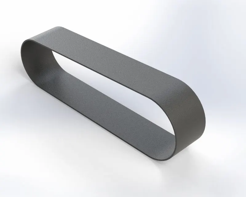
2.1. TRANSMISSION BELT:
A belt is an element which is used to transmit rotating motion from one end of a pulley to the other end of a pulley. They are the cheapest utility for power transmission between shafts that may not be axially aligned.
The sketch tools which are used for designing the transmission belt are line and arc. Then the tangent relation is given and the sketch thus created is given an offset. Then it is extruded using Extrude Boss/Base Command. After which fillets are created at the edges. Finally, the appearance of the belt is modified to rubber.
The following are some of the tools and features which are used to create the transmission belt:
- Sketch
- Straight Line
- Arc
- Offset Entities
- Extrude Boss / Base
- Fillet
- SKETCH
The sketch tool is used to create 2D drawing of the part in Solidworks. The sketch is the basics of most 3D models. Creating a model usually begins with sketch. From the sketch, one can create features. We can combine one or more feature to make a part. Then, we combine and mate the appropriate parts to create an assembly. From the parts or assemblies, we can then create drawings.
A sketch is a 2D profile or cross section. To create a 2D sketch, we use a plane or a planer face. The following are some of the tools which are used in sketch while designing the transmission belt:
- STRAIGHT LINE:
The shortest distance between two points is said to be known as straight lines. Here in the design of transmission belt, the straight line is used to create the 2D drawing.
- ARC:
While drawing straight line, if the cursor is brought back to its original position, then it creates an arc. This arc will represent the curve at the end of the transmission belt.
- OFFSET ENTITIES:
In order to create the thickness of the belt drive, this option can be utilized. “Offset Entities” will offset the line and arc to a certain distance in outward direction thus creating some space to add material for compensating thickness of the belt.
- EXTRUDE BOSS / BASE:
This feature is used to create solid material and hence helping us to view the 3D picture of the product. It is created from the sketch which is drawn previously.
- FILLET:
The fillet is used to create rounded internal or external face on the part. We can fillet all edges of a face, selected sets of faces, selected edges or edge loop.
- APPEARANCE:
The appearance is used to improve the aesthetic looks of the product and also it helps to make the product to look real. Solidworks is having a library of materials from which one can select the required one and is based on the type of product being designed.
- COMMON PROCEDURE:
- Open SolidWorks software – click on new – click “part” in new Solidworks document window – click “ok”.
- Click on front plane – click on “sketch”.
- Click “straight line” – Draw a straight line to the right of origin – make the straight line into an arc by returning the cursor to the end of the line and then extending it – then draw another straight line – draw another arc thus closing the entire drawing.
- Relation – Make sure that all the curves are tangent to the straight lines.
- Offset – Select the sketch and then click on “Offset Entities”. Offset the entire sketch thus creating thickness for the belt – Exit sketch.
- Select the sketch – Click on “Extrude Boss / Base” – Extrude the sketch.
- Create Fillet by selecting the inner and outer surface.
- Appearance – In appearance - Select “Rubber” as the material.
- Save the file in the name of “Transmission Belt”
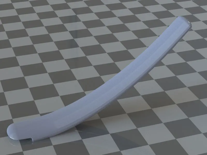
- KICK STAND:
A kickstand is a component of a two-wheeler which is used to support the vehicle when it is not moving.
The following are some of the tools used to create the kick stand
- Sketch
- Ellipse
- Spline
- Rectangle
- Loft
- Dome
- Extrude Cut
- Split
- Fillet
- Appearance
- SKETCH:
The sketch tool is used to create 2D drawing of the part in Solidworks. The sketch is the basics of most 3D models. Creating a model usually begins with sketch. From the sketch, one can create features. We can combine one or more feature to make a part. Then, we combine and mate the appropriate parts to create an assembly. From the parts or assemblies, we can then create drawings.
A sketch is a 2D profile or cross section. To create a 2D sketch, we use a plane or a planer face.
The following are some of the tools which are used in sketch for the creating the kick stand:
- ELLIPSE:
It is used to create 2D Ellipse. Since the front end and rear end of the kick stand are of elliptical shape, we use this option in sketch.
- SPLINE:
Splines are used to draw complex curves. Solidworks supports two types of splines, B-splines and style splines. We can use B-splines to create complex curves. One can define and modify them using several controls including spline points, spline handles and control polygons.
- RECTANGLE:
It is a sketching tool with different drawing methods in solid works. Methods to create a rectangle are: Corner Rectangle, Center Rectangle, 3-point corner Rectangle, 3-point center Rectangle and Parallelogram.
- LOFT:
A loft feature in Solidworks allows us to generate complex geometry in a single feature. It does this by interpolating surfaces between various cross-section of a model. These cross-sections can be sketches, faces or edges. In the loft interface, these cross-sections are considered as Loft Profiles.
- DOME:
This tool is used to create domes on a 3D parts or shapes. The domes are created at the top end and bottom end of the kick stand.
To access the Dome Tool: Go to Drop Down Menu – Insert – Feature – Dome.
- EXTRUDE CUT:
This feature is used to remover material at the bigger end of the kick stand thus allowing a free space to create pivoting shaft.
- SPLIT:
The split feature is used to cut solid geometry with faces of surfaces, solids or sketch.
- FILLET:
The fillet is used to create rounded internal or external face on the part. We can fillet all edges of a face, selected sets of faces, selected edges or edge loop.
- APPEARANCE:
The appearance is used to improve the aesthetic looks of the product and also it helps to make the product to look real. Solidworks is having a library of materials from which one can select the required appearance and is based on the type of product being designed.
- PROCEDURE
- After opening the software, press control + N or simply click the ‘new’ button on Main Menu and then click on “part” in the “New SolidWorks documents” Window and press ok.
- Rename the Right plane as Midplane
- Click on sketch – select the front plane – then draw an ellipse
- Exit sketch – select mid plane – new sketch – Draw a standard spline – exit sketch
- Create a new plane from reference geometry – Plane – select the spline – then select the end point of spline – click ok
- Select the new plane – sketch – click normal to view – draw an ellipse of same dimension as the previous one.
- Select the mind point of ellipse – control select the end point of spline – from the quick context menu select “make pierce” – Exit sketch
- Create Loft: From feature tab select “Lofted Boss / Base – Select the Elliptical profiles on the two ends of the spline – Under centerline parameter – select the spline – click ok.
- Create Dome: Go to Insert Tab on Main Menu – Feature – Dome -Select the face needed to create the dome -click ok.
- To Create cut out at larger end for pivoting kick stand: Select midplane – create sketch- select rectangle – Center point rectangle – with the center at the origin create a rectangle – Exit Sketch.
- Create Extrude cut: From the Feature Tab – Select Extrude Cut – Select “through all both” and then click ok.
- Levelling the end: Select plane1 – click sketch – select line – select Mid-point line option – draw a straight line near and down to the origin. Relation – Select the midpoint of the line and Control select the origin and give the relation as vertical, Select the line and give the relation as horizontal – Split tool (select the split tool from Main Menu – Insert – Feature – Split) – Select the sketch – Click on cut part – select the area which needed to be removed or else just give the tick mark in the check box against the correct area which needed to remove – make sure that “Consume cut bodies” is selected – Click ok.
- Creating Boss at bigger end for pivoting: Select top plane – sketch – Draw a circle – Exit sketch – Extrude this sketch up to next in direction one and two – click ok.
- Fillets: select fillet from feature tab – select the inner two faces which are near to the pivoting shaft – in the quick context menu select “Internal Face” – Click ok.
- Appearance: Expand Feature Manager Design Tree up to Display Paint – Click display paint – select Appearance – on the task pan select “Appearance – metal – chromium plate.
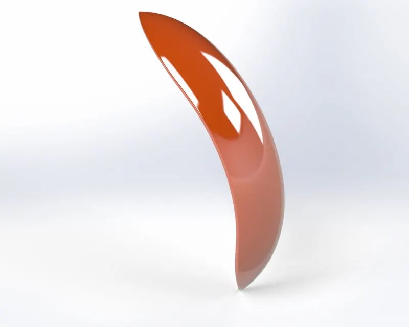
- FRONT FENDER:
The front fender acts like a mud guard. It prevents the spraying up of mud and other liquid substances from the road, when the wheel is rotating at higher speeds.
The following are some of the tools which are used to design the front fender of an American Chopper in Solidworks.
- Sketch
- Point Arc
- Offset Entities
- Extend Entities
- Trim Entities
- Dynamic Mirror Entities
- Revolve
- Split
- Fillet
- Appearance
- SKETCH:
The sketch tool is used to create 2D drawing of the part in Solidworks. The sketch is the basics of most 3D models. Creating a model usually begins with sketch. From the sketch, one can create features. We can combine one or more feature to make a part. Then, we combine and mate the appropriate parts to create an assembly. From the parts or assemblies, we can then create drawings.
A sketch is a 2D profile or cross section. To create a 2D sketch, we use a plane or a planer face.
The following are some of the tools which are used in sketch for the creating the front fender
- 3 Point Arc
- Offset Entities
- Extend Entities
- Trim Entities
- Dynamic Mirror Entities
- THREE - POINT ARC:
The 3-point arc is a type of arc which is created by selecting 3 points in the plane and hence the arc of required shape and dimension is generated.
- OFFSET ENTITIES:
In order to create the outer surface of front fender, the offset entities are used. The offset entity will move the original sketch to a certain distance from the original one which is created.
- EXTEND ENTITIES:
The tool helps in extending or creating a new entity from the previous one.
- TRIM ENTITIES:
The trim entities are used to trim the extended unwanted entities which are not really required.
- DYNAMIC MIRROR ENTITIES:
The Dynamic mirror entities is used to create similar sketches or entities by mirroring the same after drawing an axis along the center.
- REVOLVE
This feature is used to create a solid or surface geometry by revolving an entity along the center axis or any other selected entity which lays along the center of the revolving path.
- SPLIT
The split feature is used to cut solid geometry with faces of surfaces, solids or
sketch.
- FILLET
The fillet is used to create rounded internal or external face on the part. We can fillet all edges of a face, selected sets of faces, selected edges or edge loop.
- APPEARANCE
The appearance is used to improve the aesthetic looks of the product and also it helps to make the product to look real. Solidworks is having a library of materials from which one can select the required appearance and is based on the type of product being designed.
- PROCEDURE:
- After opening the software, press control + N or simply click the ‘new’ button on Main Menu and then click on “part” in the “New SolidWorks documents” Window and press ok.
- After opening the SolidWorks software window, rename the front plane as “Vertical Plane Front Fender” the Top Plane as “Center Plane Front Fender” and finally the Right Plane as “Mid Plane Front Fender”
- Select the vertical plane and then click on sketch – Select 3-point arc – Place a 3-point arc above the origin.
- Relations: Select the two end points and make them horizontal, select the center point of the arc and make it parallel with the origin – Finally give the dimensions.
- Select the sketch which is drawn – select “Offset Entity” – reverse the direction ie., inward towards the origin.
- Draw two parallel vertical lines from the end points of the original arc but no need to mention any length since the length does not matters.
- Click on “Extend entities” – extend the end lines connecting the two arc.
- Click on “Trim Entities” and then trim the unwanted projecting lines – Exit Sketch.
- Right click on the sketch created – click on “Edit sketch” – select the “Line” option – Select the construction line – draw a construction line “from the origin towards right” and make the relation as horizontal – Exit sketch
- Click on Revolve Boss / Base – Select Direction 1 and give 5 degrees – then select Direction 2 and give 130 degrees – click ok.
- Appearance: select Painted – Car – Sienna
- Click on the center plane – new sketch – click “Normal to view – select line – for construction – draw a vertical construction line from the origin.
- Click on “Dynamic Mirror Entities” from Main Menu – Tools – Sketch Tools – Dynamic Mirror – Select mirror Line which is the vertical construction line drawn from the origin in the previous step.
- Draw the spline to the right of the front fender and its mirror entity will be created
- Select the split tool from Insert – Feature – split - click on cut part - select the area outside of the spline drawn – make sure to select “Consume Cut Bodies” – Click ok.
- Similarly repeat the step 12 to 1 for creating a wedge at the bottom end of the front fender.
- Create a fillet of 6mm on the outer edge of the front fender by selecting the outer surface of the part.
- Save the part file under the name “Front Fender”.
- REAR FENDER:
The front fender acts like a mud guard. It prevents the spraying up of mud and other liquid substances from the road onto the engine, when the wheel is rotating at higher speeds.
The following are some of the tools which are used to design the front fender of an American Chopper in Solidworks.
- Sketch
- 3 Point Arc
- Construction Line
- Offset Entities
- Extend Entities
- Trim Entities
- Revolve
- Split
- Fillet
- Shell
- Appearance
- SKETCH:
The sketch tool is used to create 2D drawing of the part in Solidworks. The sketch is the basics of most 3D models. Creating a model usually begins with sketch. From the sketch, one can create features. We can combine one or more feature to make a part. Then, we combine and mate the appropriate parts to create an assembly. From the parts or assemblies, we can then create drawings.
A sketch is a 2D profile or cross section. To create a 2D sketch, we use a plane or a planer face.
The following are some of the sketch tools which are used for constructing Rear Fender,
- 3 Point Arc
- Construction Line
- Offset Entities
- Extend Entities
- Trim Entities
- THREE - POINT ARC:
The 3-point arc is a type of arc which is created by selecting 3 points in the plane and hence the arc of required shape and dimension is generated.
- CONSTRUCTION LINE:
Construction lines (also known as x lines) are temporary linework entities that can be used as references when creating and positioning other objects or linework.
- OFFSET ENTITIES:
In order to create the outer surface of front fender, the offset entities are used. The offset entity will move the original sketch to a certain distance from the original one which is created.
- EXTEND ENTITIES:
The tool helps in extending or creating a new entity from the previous one.
- TRIM ENTITIES:
The trim entities is used to trim the extended unwanted entities which are not really required.
- REVOLVE
This feature is used to create a solid or surface geometry by revolving an entity along the center axis or any other selected entity which lays along the center of the revolving path.
- SPLIT
The split feature is used to cut solid geometry with faces of surfaces, solids or sketch.
- FILLET
The fillet is used to create rounded internal or external face on the part. We can fillet all edges of a face, selected sets of faces, selected edges or edge loop.
- SHELL
The shell tool hollows out a part, leaves open the faces you select, and creates thin-walled features on the remaining faces. When no face on the model is selected, one can shell a solid part, creating a closed, hollow model. One can also shell a model using multiple thicknesses.
- APPEARANCE
The appearance is used to improve the aesthetic looks of the product and also it helps to make the product to look real. Solidworks is having a library of materials from which one can select the required appearance and is based on the type of product being designed.
- PROCEDURE:
- After opening the Solidworks window rename each of the default plane with the following names:
- Front Plane – Vertical Plane Rear Fender
- Top Plane – Center Plane Rear Fender
- Right Plane – Vertical Plane Rear Fender
- Select Vertical Plane Rear Fender – click sketch – Click 3point arc – draw the three point above origin
- Relation:
- End points of arc – horizontal with each other.
- Center point of arc – vertical with origin
- Line – Construction line – from origin – to the right
- End point of construction line – Vertical in relation with the end point of arc.
- Apply dimensions.
- Offset arc by 6mm inward.
- Draw vertical line – from outer arc – from both points
- Extend entities – select end points of inner arc
- Trim entities – Trim extended unwanted surfaces – Exit Sketch.
- Click Revolve – Direction 1 – 10 degrees & in Direction 2 – 140 degrees.
- Expand display paint – select appearance of part – select painted – car – Seinna.
- Sketch – center plane -view normal to -hold alt key and left arrow.
- 3 point arc – select left edge – draw towards the right – arc must bend upwards.
- Select left point and right end point – make horizontal.
- Give dimensions
- Split tool – select cut part – select areas to remove – click ok – hide sketch.
- Fillet - select one corner – In quick context menu – select connected to start face, 3 edges – click ok
- Fillet – select outside face.
- Shell – select inside face – click shoe preview – click ok.
- Save the document as Front Fender.

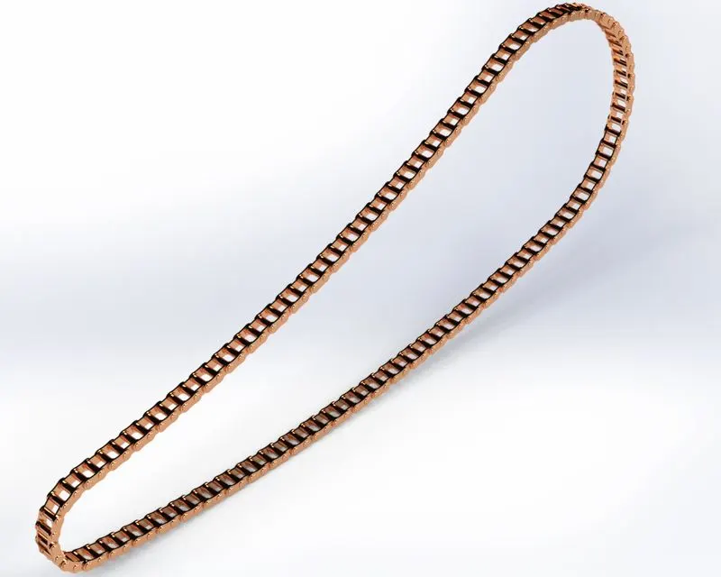
- CHAIN:
Most often, the power is conveyed by a roller chain, known as the drive chain or transmission chain, passing over a sprocket gear, with the teeth of the gear meshing with the holes in the links of the chain. The sprocket is turned, and this pulls the chain putting mechanical force into system.
The following are some of the tools which are used to design the Chain of an American Chopper in Solidworks.
- Sketch
- Line
- Circle
- 3 Point Arc
- Trim Entities
- Slot
- Convert Entities
- Create and Insert Blocks
- Extrude & Offset
- Fillet
- Curve Driven Pattern
- Creating folders for Solid Bodies
- Mirror
- Appearance
- SKETCH:
The sketch tool is used to create 2D drawing of the part in Solidworks. The sketch is the basics of most 3D models. Creating a model usually begins with sketch. From the sketch, one can create features. We can combine one or more feature to make a part. Then, we combine and mate the appropriate parts to create an assembly. From the parts or assemblies, we can then create drawings.
A sketch is a 2D profile or cross section. To create a 2D sketch, we use a plane or a planer face.
The following are some of the sketch tools which are used for constructing the chain
- Straight Line
- Circle
- 3 Point Arc
- Trim Entities
- Slot
- Convert Entities
- STRAIGHT LINE:
The shortest distance between two points is said to be known as straight lines. Here in the design of transmission belt, the straight line is used to create the 2D drawing.
- CIRCLE:
A circle is a closed two-dimensional figure in which the set of all the points in the plane is equidistant from a given point called “center.”
- 3 POINT ARC:
The 3-point arc is a type of arc which is created by selecting 3 points in the plane and hence the arc of required shape and dimension is generated.
- TRIM ENTITIES:
The trim entities are used to trim the extended unwanted entities which are not really required.
- SLOT:
Using the “Straight Slots” tool, one can draw linear slots on the sketch entity.
- CONVERT ENTITIES
One can create one or more curves in a sketch by projecting an edge, loop, face, curve, or external sketch contour, set of edges, or set of sketch curves onto the sketch plane by using convert entities.
- CREATE AND INSERT BLOCKS
One can make, save, edit, and insert blocks for drawing items and sketch entities that you use often, such as standard notes, title blocks, label positions, and so on. Also, can attach blocks to geometry or to drawing views, and you can insert them into sheet formats.
- EXTRUDE & OFFSET
This feature is used to create solid material and hence helping us to view the 3D picture of the product. It is created from the sketch which is drawn previously.
The offset option will help in placing the extruded component at the desired place.
- FILLET
The fillet is used to create rounded internal or external face on the part. We can fillet all edges of a face, selected sets of faces, selected edges or edge loop.
- CURVE DRIVEN PATTERN
The Curve Driven Pattern tool allows you to create patterns along a planar or 3D curve. To define the pattern, one can use any sketch segment, or the edge of a face (solid or surface), that lies along the plane. Also, one can base your pattern on an open curve, or on a closed curve, such as a circle.
- CREATING FOLDERS FOR SOLID BODIES
While mirroring the plates, one can avoid the tedious process of selecting individual plates by selecting all the pins and keeping them in a separate folder.
- MIRROR
This tool is used to create an opposite-hand version of a sketch, part or assembly component, which is positioned symmetrically about a plane
- APPEARANCE
The Appearances command displays the colors of faces, features, bodies, and the part and is a shortcut to editing appearances. You can see the hierarchy of colors by expanding the command. Color selections made in the Appearances Property Manager supersede colors set on the Document Properties tab.
- Procedure:
- After opening the Solidworks window rename each of the default plane with the following names:
- Front Plane – Mid Plane Chain
- Top Plane – Center Plane Chain
- Right Plane – Front Plane Chain
- After opening the Solidworks software click “New” and then select “Part” from the popup window titled “New SolidWorks Document” then click ok.
- Select Mid Plane Chain – Click Sketch – Click Line – for construction – start at origin – to right – horizontal - 650mm – then vertically down – 147mm.
- 1st Circle – at origin – 289mm – 2nd Circle – at 2nd point which is at a distance 147mm – Dia:99mm.
- Add a little droop to the chain”
- 3-point arc – don’t snap with points on circle – start at right end of bigger circle and going down to small sprocket –
- Relation of arc with circle – Tangent – Make sure of it.
- Trim Entity – Remove the inner sides of the circle.
- Add Dimensions.
- Line – For construction – horizontal above chain path – Distance:15.13mm
- Circle – 2No’s – at the end points of the construction line as drawn in the previous step – Both of the circles should be equal - to replicate pins at the end of above construction line – size – 8mm dia.
- Another concentric circle – at both ends of construction line – both equal – size – 12mm dia
- 3-point arc – not to snap with any quadrants of circle – draw one on top and another at bottom of each circle – Radius of arc – 28mm – Arc relation with circle - Tangent.
- Trim Entity – remove the circle curves which lies in between the two-arc connection the two circles.
- Another Line – For construction – horizontal above chain path and to the right of the previous sketch – Distance between two end points:15.13mm
- Another Circle - 2No’s – at the end points of the construction line – Both of the circles should be equal – size – 8mm dia.
- Slot – click the centers of the two circles – Drag outside – Radius - 5.5mm
- Create Block – Drag mouse cursor on last drawn sketch - from right bottom to left top – In quick context menu – select make block – click ok – Right click on the block in feature tree – click save block – name the block as “Chain link 1. – Click ok. (One can select block by going to Main Menu – Tools – Blocks – Save).
- Save the external link in the same manner – Name the file name as “Chain link 2”.
- Sketch – Mid plane chain – Insert block – (1. Right click on tab – turn on block or 2. Tools Menu – Blocks – Insert or 3. Customize ‘S’ key to include add block.) - Browse – open “Chain Link 1” and “Chain Link 2”
- Place link plate at the vertices of the path drawn for the chain.
- Make the center of Chain link 1 to be in coincident with the path of the chain similarly make the center of chain link 2 to be in coincident with the path of the chain.
- Extrude – In selected contours – right click – clear selection – select areas which are needed to be extruded – do mid plane extrusion of 25mm
- Select sketch 3 and then turn sketch on
- Extrude – right click on selected contours – clear selection – select the link plate which needed to be extruded – end plate – 2mm – don’t merge results – offset value – 9.5mm.
- Select sketch 3 – extrude – right click to clear selection – select area of pin – select vertex to offset – vertices along the inside of outer link – reverse direction – deselect merge results.
- Hide sketch
- Apply fillets – 0.5mm – to the end of pins.
- Curve Driven Pattern – select larger area – select bodies to pattern – select outer and inner plate – give no of instances as 20 – give ok.
- Put all pins in pin folder
- Insert blocks again and create fillets
- Create link plates
- Make curve driven pattern – select links
- Repeat above steps till the chain links are completed
- Select end of link plate – go into solid body folder – right click and delete that body.
- Sketch mid plane – grab both end pin – convert entity – create slot.
- Extrude pin – from vertex – deselect merge results.
- Organize and put pins in the solid body folder.
- Select all end plates – click mirror – select mid plane in tree from drawing area – click ok.
- Put all plates in separate folder & save the file as chain.
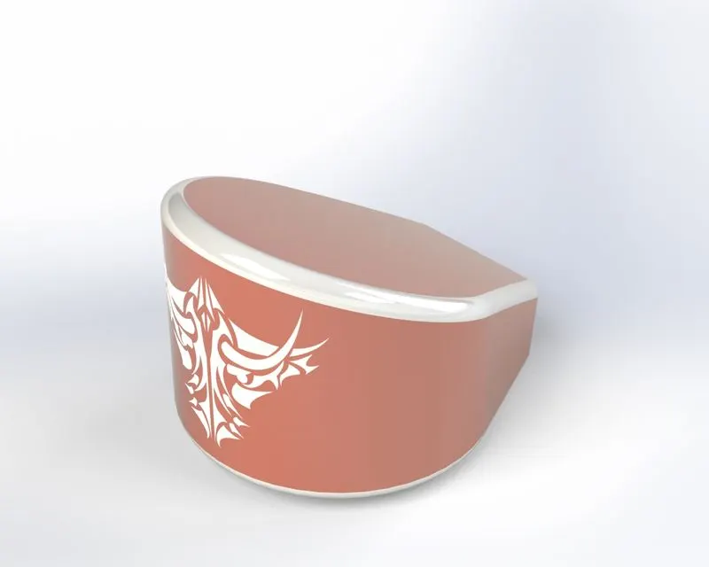
- OIL TANK:
A fuel tank (also called as petrol or gas tank) is a safe container for flammable fluids. Though any storage tank for fuel may be so called, the term is typically applied to part of an engine system in which the fuel is stored and propelled (fuel pump) or released (pressurized gas) into an engine. Fuel tanks range in size and complexity from the small plastic tank of a butane lighter to the multi-chambered cryogenic.
The following are some of the tools which are used to design the Oil Tank of an American Chopper in Solidworks.
- Sketch:
- Line (Construction Line)
- Dynamic Mirror Entities
- Arc
- Spline
- Extrude
- Combine
- Fillet
- Shell
- Appearance
- SKETCH:
The sketch tool is used to create 2D drawing of the part in Solidworks. The sketch is the basics of most 3D models. Creating a model usually begins with sketch. From the sketch, one can create features. We can combine one or more feature to make a part. Then, we combine and mate the appropriate parts to create an assembly. From the parts or assemblies, we can then create drawings.
A sketch is a 2D profile or cross section. To create a 2D sketch, we use a plane or a planer face.
The following are some of the sketch tools which are used for constructing the Oil Tank:
- LINE (CONSTRUCTION LINE):
Construction lines (also known as x lines) are temporary linework entities that can be used as references when creating and positioning other objects or linework.
- DYNAMIC MIRROR ENTITIES
The Dynamic mirror entities is used to create similar sketches or entities by mirroring the same after drawing an axis along the center.
- ARC
While drawing straight line, if the cursor is brought back to its original position, then it creates an arc. This arc will represent the curve at the end of the transmission belt.
- SPLINE
Splines are used to draw complex curves. Solidworks supports two types of splines, B-splines and style splines. We can use B-splines to create complex curves. One can define and modify them using several controls including spline points, spline handles and control polygons.
- EXTRUDE
This feature is used to create solid material and hence helping us to view the 3D picture of the product. It is created from the sketch which is drawn previously.
- COMBINE
The common function allows us to add two bodies together, and keep the area that is common to them.
- FILLET
The fillet is used to create rounded internal or external face on the part. We can fillet all edges of a face, selected sets of faces, selected edges or edge loop.
- SHELL
The shell tool hollows out a part, leaves open the faces you select, and creates thin-walled features on the remaining faces
- APPEARANCE
The Appearances command displays the colors of faces, features, bodies, and the part and is a shortcut to editing appearances. You can see the hierarchy of colors by expanding the command. Color selections made in the Appearances Property Manager supersede colors set on the Document Properties tab.
- PROCEDURE:
- After opening the Solidworks window rename each of the default plane with the following names:
- Front Plane – Mid Plane Oil Tank
- After opening the Solidworks software click “New” and then select “Part” from the popup window titled “New SolidWorks Document” then click ok.
- Sketch – Top Plane – Line – For construction – from origin – to left – 230mm
- Sketch – point – Locate vertically above the origin – select origin – ctrl select point – make vertical – vertical dimension – 146mm.
- Dynamic Mirror entities – select horizontal construction line – from left point – vertically upward – 50mm – up to the right at angle - take cursor back to change it into an arc – then join it with the origin.
- Take center point of arc – ctrl plus select horizontal construction line – make it coincident.
- Select angled line – ctrl select point – make coincident.
- Extrude – 170mm in direction 1 – and 10mm in direction 2.
- Sketch – midplane oil tank – normal to – line tool – from origin – vertically upward – 166mm – double click to end the line tool.
- Start again at origin – down into left near left corner – upto left - make it coincident with the left edge – hit escape.
- Spline – from top left point of left edge – 2nd point in middle of part – end at vertical line – hit escape.
- Angle between vertical right side line and angled line = 92.5 degrees & horizontal distance = 215mm – for angled line.
- Dimension of spline – Midpoint of spline – down to origin – vertical dimension = 113mm, horizontal distance = 107.5mm, upper left point to origin – vertical dimension = 42mm – Exit Sketch.
- In Feature Tab – Select Extrude Boss/Base – In Direction 1 – Select “Through all” & in Direction 2 – Select “Through all” – Deselect Merge Results.
- Main Menu – Insert - Feature - Combine – operation type – Common – Select “Both solid bodies” – Click show preview – click ok.
- Expand Display paint – Appearance - painted – car – Sienna.
- Fillet – 10mm – right top corner – quick context menu – Internal to feature – Click ok.
- Display paint – Appearance of fillet – painted – car – white.
- Shell – 3mm – click ok.
- Expand solid bodies folder – change transparency of part – change fillet edge transparency.
- Save the part as “Oil Tank”.
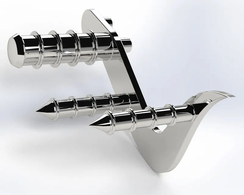
- PEDAL:
Apart from making your rides enjoyable, good bike footrests ensure that your on-road balance is right and you can avoid any untoward mishap.
The following are some of the tools which are used to design the Pedal of an American Chopper in Solidworks.
- Sketch:
- Line – Construction line
- 3 Point Arc
- Line
- Circle
- Splines
- Fillet
- Extrude
- Fillet
- Revolve
- Dome
- Chamfer
- Linear Pattern
- Appearance
- SKETCH
The sketch tool is used to create 2D drawing of the part in Solidworks. The sketch is the basics of most 3D models. Creating a model usually begins with sketch. From the sketch, one can create features. We can combine one or more feature to make a part. Then, we combine and mate the appropriate parts to create an assembly. From the parts or assemblies, we can then create drawings.
A sketch is a 2D profile or cross section. To create a 2D sketch, we use a plane or a planer face.
The following are some of the sketch tools which are used for constructing the Pedal:
- Line – Construction line
- 3 Point Arc
- Straight Line
- Circle
- Splines
- Fillet
- LINE – CONSTRUCTION LINE:
Construction lines (also known as x lines) are temporary line entities that can be used as references when creating and positioning other objects or linework.
- THREE - POINT ARC
The 3-point arc is a type of arc which is created by selecting 3 points in the plane and hence the arc of required shape and dimension is generated.
- STRAIGHT LINE
The shortest distance between two points is said to be known as straight lines. Here in the design of transmission belt, the straight line is used to create the 2D drawing.
- CIRCLE
A circle is a closed two-dimensional figure in which the set of all the points in the plane is equidistant from a given point called “center.”
- SPLINES
Splines are used to draw complex curves. Solidworks supports two types of splines, B-splines and style splines. We can use B-splines to create complex curves. One can define and modify them using several controls including spline points, spline handles and control polygons.
- FILLET
The fillet is used to create rounded internal or external face on the part. We can fillet all edges of a face, selected sets of faces, selected edges or edge loop.
- EXTRUDE
This feature is used to create solid material and hence helping us to view the 3D picture of the product. It is created from the sketch which is drawn previously
- FILLET
The fillet is used to create rounded internal or external face on the part. We
can fillet all edges of a face, selected sets of faces, selected edges or edge
loop.
- REVOLVE
This feature is used to create a solid or surface geometry by revolving an entity along the center axis or any other selected entity which lays along the center of the revolving path.
- DOME
This tool is used to create domes on a 3D parts or shapes. The domes are created at the top end and bottom end of the kick stand.
To access the Dome Tool: Go to Drop Down Menu – Insert – Feature – Dome.
- CHAMFER
SolidWorks chamfer tool is one of the useful tools in SolidWorks cad software, which helps to cut (45-degree angle with normal surface) or make edges or corner (vertex) of 3D model in straight.
- LINEAR PATTERN
Use linear patterns to create multiple instances of one or more features that you can space uniformly along one or two linear paths.
- APPEARANCE
The Appearances command displays the colors of faces, features, bodies, and the part and is a shortcut to editing appearances. You can see the hierarchy of colors by expanding the command. Color selections made in the Appearances Property Manager supersede colors set on the Document Properties tab.
- PROCEDURE:
- After opening the Solidworks software click “New” and then select “Part” from the popup window titled “New SolidWorks Document” then click ok.
- Sketch – Front Plane – Line – For construction – Select Midpoint – draw it vertically from origin.
- Deselect – Midpoint – draw horizontal from both end points.
- Vertical Dimension – 35mm
- Draw lines from end points of horizontal reference both horizontal and also equal.
- Dimension end point -72mm away
- 3-point arc – going from end point of lines – apply tangency with both construction line – as well as vertical construction lines.
- Line – from upper end point of line – down to the right-hand side & from lower end point of line – down to right hand side.
- Make sure both lines are parallel – Apply dimensions
- Line – for construction – right hand section – draw vertically – apply dimensions – leave the other end undefined.
- Circle 1- at the center point of arc – dia -16mm
- Circle 2 – to the right of the arc – center point of both circle – horizontal – circle 1 & 2 should be of equal size – Center point distance = 47mm
- Another Circle 3 – Between two inclined lines – 15mm dia – 13mm vertical distance from origin & 125mm horizontally from origin.
- Another Circle 4 – Below horizontal construction line which is at 255mm from the origin horizontally – Dia = 15mm and 42mm above the horizontal lower line & 218.4mm horizontally from origin.
- Spline 1 from end point of upper slant line to upper end point – lower end point should be tangent with the lower handle
- Activate upper handle – 15degree and 250mm way
- Lower handle – way -200mm
- Spline 2: From bottom edge of lower slant line to upper horizontal line – lower handle in tangent with slant line – Activate upper handle – 35degree with horizontal and 245 mm away and Lower handle 545 mm way.
- Fillet – 60mm – at upper and lower horizontal lines touching the slant lines – select corners constrained – check ok – Click ok – Exit sketch.
- Extrude – go to selected contour – clear selection – extrude the profiles and the holes – 8mm thick.
- Select sketch 1 again – do another extrude – click selected contours – select first two holes – opposite direction – merge results – click ok.
- Fillets – 1mm – outside face – and inside face.
- Sketch the top plane – line – for construction – 2nd part to the right – at midpoint of the line to the front end.
- Line – from front end of construction line – downwards – then to right – sketch the given profile.
- Give dimensions
- Revolve – Make sure to check merge results.
- Insert – Feature – Dome – at the end of foot pedal – 3mm.
- Fillet – 1mm – at the end edge of dome and sharp edges – at wo back faces of mounting bosses – click ok.
- Select sketch 1- another extrude – clear selection in selected contours – take two smaller circles – extrude – select From as “Surface / Face / Plane” distance – 100mm – click ok.
- Chamfer – “Distance Distance” – D1 as 16mm and D2 as 9mm – select end edges of the newly extruded first part – click ok.
- Repeat the above process – D1 – 16mm and D2 as 7.50mm – select 2nd part which is extruded which is having smaller diameter – click ok.
- Sketch at front face of the part – offset outer edges of two newly extruded parts by a distance of 2.50mm
- Select outer edge of footpedal – offset it also by 2mm
- Extrude these sketches by 2.5mm – In From give it as “Offset” and give the value as 20mm
- Fillet – inner sections and outer edges of footpedal – front and back faces of new rings – all three rings – 1mm.
- Linear Pattern – select one of tangent edges – Distance as 20mm – Instances as 4 - Also under Features select “Fillet and Boss Extrude” in the tree from drawing area – click ok.
- Fillet – 1mm – select back side of bigger bar front end and front end of smaller bar – click ok.
- Go back to filler 4 – select corners of each circular bar which starts from the flat bar -1mm – click ok.
- Save the file as “Pedal”.
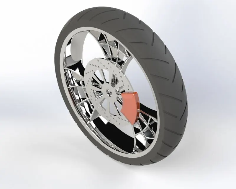
- FRONT-WHEEL:
The front wheel is the rotating part of a two-wheeler on which the vehicle balances and also it is used to steer the vehicle while running.
The following are some of the tools which are used to design the Front Wheel of an American Chopper in Solidworks.
- Sketch
- Straight Line and Construction Line
- 3 Point Arc
- Fillet
- Spline
- Mirroring
- Offset entities
- Power Trim
- Circle
- Convert entity
- Linear Pattern
- Extrude Boss / Bass
- Extrude Cut
- Revolve
- Circular Pattern
- Hole Wizard
- Combine
- Chamfer
- Appearance
- SKETCH
The sketch tool is used to create 2D drawing of the part in Solidworks. The sketch is the basics of most 3D models. Creating a model usually begins with sketch. From the sketch, one can create features. We can combine one or more feature to make a part. Then, we combine and mate the appropriate parts to create an assembly. From the parts or assemblies, we can then create drawings.
A sketch is a 2D profile or cross section. To create a 2D sketch, we use a plane or a planer face.
- STRAIGHT LINE AND CONSTRUCTION LINE
The shortest distance between two points is said to be known as straight lines. Here in the design of transmission belt, the straight line is used to create the 2D drawing.
Construction lines (also known as x lines) are temporary linework entities that can be used as references when creating and positioning other objects or linework.
- 3 POINT ARC
The 3-point arc is a type of arc which is created by selecting 3 points in the plane and hence the arc of required shape and dimension is generated.
- FILLET
The fillet is used to create rounded internal or external face on the part. We can fillet all edges of a face, selected sets of faces, selected edges or edge loop.
- SPLINE
Splines are used to draw complex curves. Solidworks supports two types of splines, B-splines and style splines. We can use B-splines to create complex curves. One can define and modify them using several controls including spline points, spline handles and control polygons.
- MIRRORING
This tool is used to create an opposite-hand version of a sketch, part or assembly component, which is positioned symmetrically about a plane
- OFFSET ENTITIES
In order to create the outer surface of front fender, the offset entities are used. The offset entity will move the original sketch to a certain distance from the original one which is created.
- POWER TRIM
The trim entities are used to trim the extended unwanted entities which are not really required.
- CIRCLE
A circle is a closed two-dimensional figure in which the set of all the points in the plane is equidistant from a given point called “center.”
2.8.1.9. CONVERT ENTITY
One can create one or more curves in a sketch by projecting an edge, loop, face, curve, or external sketch contour, set of edges, or set of sketch curves onto the sketch plane by using convert entities.
- LINEAR PATTERN:
The Linear Pattern is used to duplicate one single entity of unique size more than one time in a linear direction or straight direction.
- EXTRUDE BOSS / BASS
This feature is used to create solid material and hence helping us to view the 3D picture of the product. It is created from the sketch which is drawn previously.
- EXTRUDE CUT
This feature is used to remover material at the bigger end of the kick stand thus allowing a free space to create pivoting shaft.
- REVOLVE
This feature is used to create a solid or surface geometry by revolving an entity along the center axis or any other selected entity which lays along the center of the revolving path.
- CIRCULAR PATTERN
The Circular Pattern is used when one had to pattern one or more features around an axis.
- HOLE WIZARD
Hole Wizard is a tool inside SOLIDWORKS that allows you to quickly create holes within a part or assembly without the need of drawing or using multiple features.
- COMBINE
The common function allows you to add two bodies together, and keep the area that is common to them.
- CHAMFER
This tool is used to create smooth edges by removing the corners after specific dimensions are given.
- APPEARANCE
The Appearances command displays the colors of faces, features, bodies, and the part and is a shortcut to editing appearances. You can see the hierarchy of colors by expanding the command. Color selections made in the Appearances Property Manager supersede colors set on the Document Properties tab.
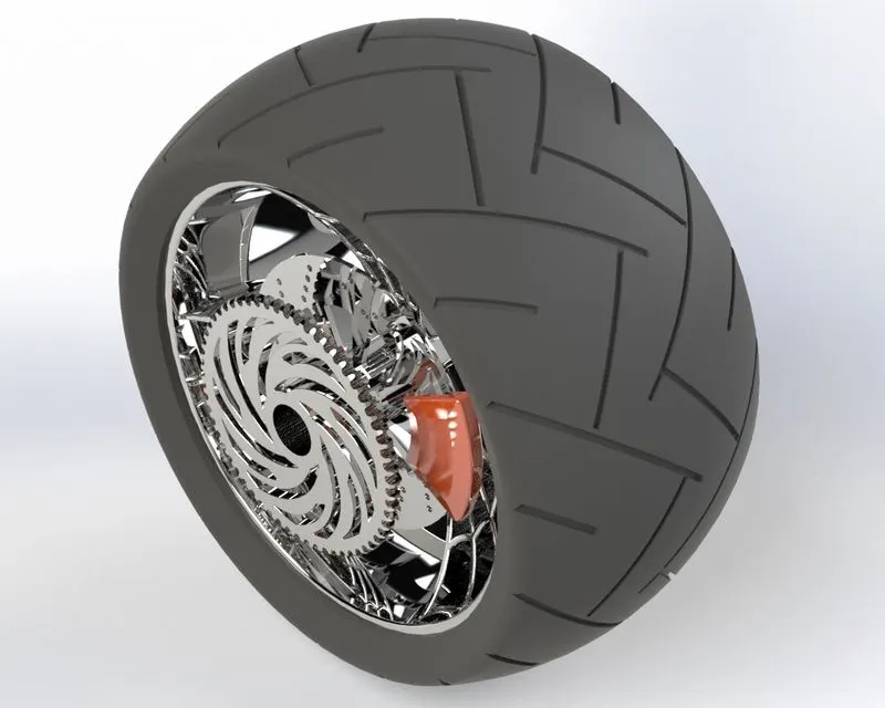
- REAR-WHEEL
The rear wheel plays a very important part not only in balancing the vehicle but also in transmission. Attached to the rear wheel is the transmission chain which in turn is connected to the engine sprocket. The design of rear wheel is very similar to that of front wheel except some additional components like sprocket, and central axis etc.
The following are some of the tools which are used to design the Rear Wheel of an American Chopper in Solidworks.
- Sketch
- Straight Line and Construction Line
- 3 Point Arc
- Fillet
- Spline
- Mirroring
- Offset entities
- Power Trim
- Circle
- Convert entity
- Linear Pattern
- Extrude Boss / Bass
- Extrude Cut
- Revolve
- Circular Pattern
- Hole Wizard
- Combine
- Chamfer
- Appearance
- SKETCH:
The sketch tool is used to create 2D drawing of the part in Solidworks. The sketch is the basics of most 3D models. Creating a model usually begins with sketch. From the sketch, one can create features. We can combine one or more feature to make a part. Then, we combine and mate the appropriate parts to create an assembly. From the parts or assemblies, we can then create drawings.
A sketch is a 2D profile or cross section. To create a 2D sketch, we use a plane or a planer face.
- STRAIGHT LINE & CONSTRUCTION LINE
The shortest distance between two points is said to be known as straight lines. Here in the design of transmission belt, the straight line is used to create the 2D drawing.
Construction lines (also known as x lines) are temporary linework entities that can be used as references when creating and positioning other objects or linework.
- THREE - POINT ARC
The 3-point arc is a type of arc which is created by selecting 3 points in the plane and hence the arc of required shape and dimension is generated.
- FILLET
The fillet is used to create rounded internal or external face on the part. We can fillet all edges of a face, selected sets of faces, selected edges or edge loop.
- SPLINE
Splines are used to draw complex curves. Solidworks supports two types of splines, B-splines and style splines. We can use B-splines to create complex curves. One can define and modify them using several controls including spline points, spline handles and control polygons.
- MIRRORING
This tool is used to create an opposite-hand version of a sketch, part or assembly component, which is positioned symmetrically about a plane
- OFFSET ENTITIES
In order to create the outer surface of front fender, the offset entities are used. The offset entity will move the original sketch to a certain distance from the original one which is created.
- POWER TRIM
The trim entities are used to trim the extended unwanted entities which are not really required.
- CIRCLE
A circle is a closed two-dimensional figure in which the set of all the points in the plane is equidistant from a given point called “center.”
- CONVERT ENTITY
One can create one or more curves in a sketch by projecting an edge, loop, face, curve, or external sketch contour, set of edges, or set of sketch curves onto the sketch plane by using convert entities.
- LINEAR PATTERN:
The Linear Pattern is used to duplicate one single entity of unique size more than one time in a linear direction or straight direction.
- EXTRUDE BOSS / BASS
This feature is used to create solid material and hence helping us to view the 3D picture of the product. It is created from the sketch which is drawn previously.
- EXTRUDE CUT
This feature is used to remover material at the bigger end of the kick stand thus allowing a free space to create pivoting shaft.
- REVOLVE
This feature is used to create a solid or surface geometry by revolving an entity along the center axis or any other selected entity which lays along the center of the revolving path.
- CIRCULAR PATTERN
The Circular Pattern is used when one had to pattern one or more features around an axis.
- HOLE WIZARD
Hole Wizard is a tool inside SOLIDWORKS that allows you to quickly create holes within a part or assembly without the need of drawing or using multiple features.
- COMBINE
The common function allows you to add two bodies together, and keep the area that is common to them.
- CHAMFER
This tool is used to create smooth edges by removing the corners after specific dimensions are given.
- APPEARANCE
The Appearances command displays the colors of faces, features, bodies, and the part and is a shortcut to editing appearances. You can see the hierarchy of colors by expanding the command. Color selections made in the Appearances Property Manager supersede colors set on the Document Properties tab.
- FRONT FORK
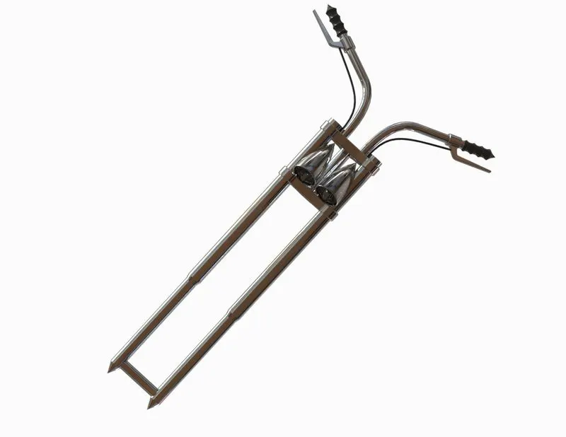
The front fork carries the front wheel suspension for the vehicle. I also help in steering the vehicle. Also attached with it are the head lights, accelerator, clutch lever, lever for front brake and all the electronic control switches required for the bike. The major role of a bike’s front fork is to absorb the maximum vibration from the road while travelling.
The following are some of the tools which are used to design the Front Fork of an American Chopper in Solidworks.
- Sketch
- Straight Line and Construction Line
- 3 Point Arc
- Fillet
- Spline
- Mirroring
- Projection of curves
- Offset entities
- Power Trim
- Circle
- Convert entity
- Linear Pattern
- Revolve
- Extrude Boss / Bass
- Projection of Planes
- Combine
- Swept Boss/Base
- Appearance
- Sketch
- Projection of Curves:
It is a tool you which is used to form 3D curves from two 2D curves drawn on two different planes. The curves for sweeping handle bars are generated using this method.
- CHASSIS:
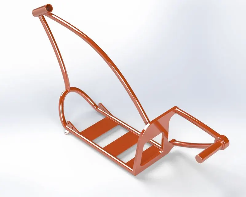
The chassis is the main structural component of an automobile. It is the part which withstands the load of the entire assembly of the vehicle.
The following are some of the tools which are used to design the Chassis of an American Chopper in Solidworks.
- Sketch
- Inserting and Positioning Sketch Picture
- Straight Line and Construction Line
- Spline
- Offset entities
- Power Trim
- Circle
- Convert entity
- Projection of lines
- Revolve
- Extrude Boss / Bass
- Projection of Planes
- Combine
- Swept Boss/Base
- Appearance
- ENGINE:
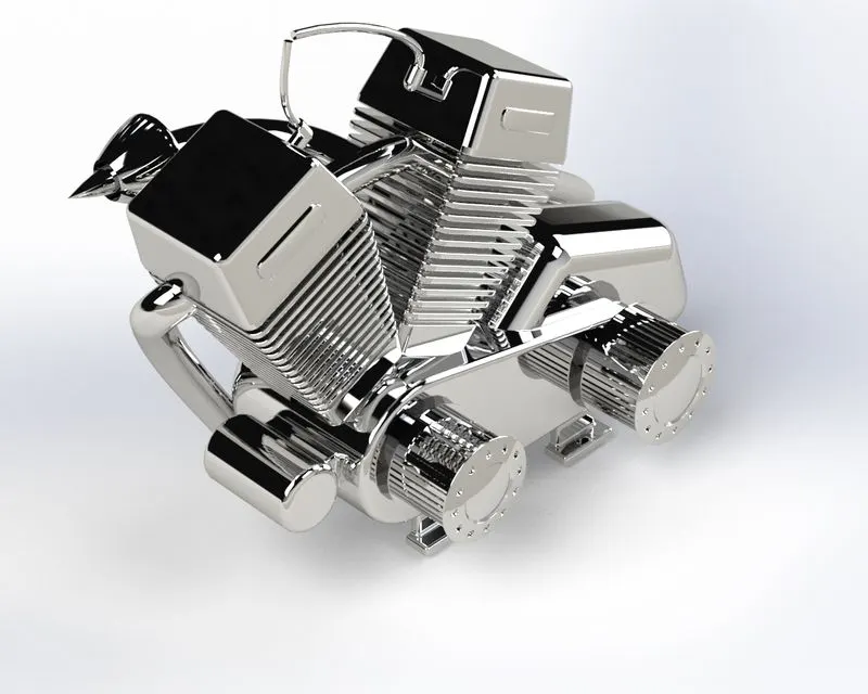
The engine is like a heart to an automobile which generates the required power to run the vehicle. The following are some of the tools which are used to design an engine of an American chopper.
- Sketch
- Inserting Sketch Picture & Positioning the origin
- Line (Straight & Construction Line)
- Center Point Rectangle
- Circle
- Offset Entities
- Projection of Curves
- Convert Entities
- Planes Projection
- Extrude Boss/Base & giving draft
- Extrude Cut
- Revolve
- Dome
- Split
- Linear Pattern
- Chamfer
- Reference Plane Creation
- Mirroring
- Swept Boss / Base
- Gas Tank:
The fuel tank is the storage area for the fuel. Today’s modern fuel tank consists of additional features to reduce the evaporation rate of fuel and also leak proof lock to avoid any leakage and fire in case of any accidents.
The following are some of the tools which are used to design a Fuel Tank of an American Chopper.
- Sketch
- Inserting Sketch Picture & Positioning the origin
- Line (For Construction & Straight Line)
- Loft Surface
- Swept Surface
- Boundary Surface
- Trim Surface
- Knitting the surfaces
- SKETCH
- Inserting Sketch Picture & Positioning the origin:
- The Sketch picture is inserted into the new part file window and then its origin position is changed correspondingly.
- LOFTED SURFACE
It is the simplest way to allow the software to interpolate a shape between two or more profiles. It works with solids and surfaces, and it has unique functions as well as some overlap with the Boundary feature.
- SWEPT SURFACE
Within SOLIDWORKS, a sweep is a tool that creates a solid, a cut or a surface feature by moving a profile along a path.
- BOUNDARY SURFACE
The Boundary surface allows a bigger range of arrangements of curves compared to the Loft. Loft requires at least two profiles, but it can work with or without guide curves. Boundary requires at least two curves, and doesn’t care about which directions or combinations. It can use one Direction 1 and one Direction 2, or two Direction 1, or two Direction 2.
- TRIM SURFACE.
Primarily used to cut away material from a surface, and provides two modes: Standard and Mutual. In Standard mode, a single selection is defined as a Trim Tool, and target surfaces are trimmed accordingly. In Mutual mode, multiple surfaces are trimmed with respect to each other. Examples of each mode are shown below.
- KNITTING THE SURFACES
When working with surfaces in SOLIDWORKS you would typically be converting Surface into Solid using the Knit Surface or Thicken Surface.
It Combines two or more adjacent non interfacing surfaces together.
- ASSEMBLY IN SOLIDWORKS:
In Solidworks, Assembly is used make a complex model made of other models previously created. It combines all the parts which are individually modelled as a single part file into a complex part.
The following are some of the tools which are used to during assembly of an American Chopper.
- INSERTING COMPONENTS:
- Initially all the parts are opened inside Solidworks and then new assembly window is opened
- Into this window, starting from chassis each part files are inserted
- MATE
Mates create geometric relationships between assembly components. Hence based on the components and their position, their corresponding mates are created
- EDIT COMPONENTS
Solidworks provides an option of editing the parts within the assembly window. Hence the side stand is remodified by opening the part file inside assembly window and changing its dimensions so that it may look shorter. Also, other components are edited if required
- MIRROR COMPONENTS
Inside the assembly, the foot pedal is assembled in one side of the bike and then it is mirrored to the other side correspondingly.
- APPLYING DECALS, LIGHTS & CAMERA SETUP INSIDE SOLIDWORKS USING PHOTOVIEW 360.
Rendering or image synthesis is the process of generating a photorealistic or non-photorealistic image from a 2D or 3D model by means of a computer program. The resulting image is referred to as the render. Multiple models can be defined in a scene file containing objects in a strictly defined language or data structure. The scene file contains geometry, viewpoint, texture, lighting, and shading information describing the virtual scene. The data contained in the scene file is then passed to a rendering program to be processed and output to a digital image or raster graphics image file. The term “rendering” is analogous to the concept of artist’s impression of a scene. The term “rendering” is also used to describe the process of calculating effects in a video editing program to produce the final video output.
PhotoView 360 is a SolidWorks add-in that produces photo-realistic renderings of SolidWorks models. The rendered image incorporates the appearances, lighting, scene, and decals included with the model. PhotoView 360 is available with SolidWorks Professional or SolidWorks Premium.
The following are some of the process and tools which are used in photo view 360 and in Solidworks visualize software while rendering the American Chopper.
- Setting up of Chopper inside Solidworks Environment
- Rebuilding Side Stand
- Adding Decals to Gas tank, Rear Fender & Oil Tank
- Adjusting Colors and Editing Materials
- Changing the Scene Composition
- Creating Cameras
- Adding Lights & Background Images
- Rendering Lights
- Basic Rendering
4.1. SETTING UP OF CHOPPER INSIDE SOLIDWORKS ENVIRONMENT:
The main reason for undergoing this step is to make sure that the model rendered might look realistic. As regards the American chopper, its tires should touch the floor. Also, the automobile should lean on side stand along with the handle bar turned to left side so that the vehicle may look real when rendered. These are the process which are carried out before going for rendering.
- REBUILDING SIDE STAND:
The stand is rebuilt since it length is too high and hence it is reduced to an optimum size.
- ADDING DECALS TO GAS TANK, REAR FENDER & OIL TANK:
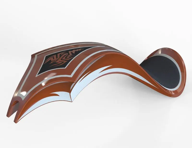
Decals are the design prepared on special paper for durable transfer on to another surface such as glass or porcelain.
Here the decals are applied onto the surfaces of Gas Tank, Rear Fender and Oil Tank.
- ADJUSTING COLORS AND EDITING MATERIALS
The colors for Front Fender, Rear Fender, Fuel Tank, and Oil Tank are modified corresponding to one’s taste.
The material is also modified correspondingly.
- CHANGING THE SCENE COMPOSITION:
To make the 3D model as realistic as possible, we add a 3D picture image and change the scene composition correspondingly. One should make sure of turning on the perspective view.
- CREATING CAMERAS:
The rendering will be looking more realistic if we add cameras to the view. This will make the 3D model more visible along the direction in which we want to view it. A camera can be added by selecting Main Menu – View – Lights and Cameras – Add Camera. The camera can be turned along all three axis and it focal point can also be adjusted.
- ADDING LIGHTS AND BACKGROUND IMAGES:
The background images and lights are added corresponding to one’s likeness. Here we can change the lights and their position which we can fix it in position. Also, one can include different HD 3D image in the background.
- RENDERING LIGHTS
We can either suppress lights or enable them. They add luminescence to the 3D model. There are four available lights inside Solidworks
- Directional Lights
- Point Lights
- Spot Light &
- Sun Light.
For American Chopper, we choose Directional Lights.
- BASIC RENDERING;
Under Render tools, if clicked on Render Preview – one can preview the rendered image inside Solidworks window. Any correction if required, can be made correspondingly.
Also, a comparison can be made between previous rendered image and the recent one and hence it will help in coming to a conclusion while selecting an image which can be well rendered.
5. RENDERING USING SOLIDWORKS VISUALIZE
The Solidworks is a tool which is used to create Solidworks rendering. We import models into Solidworks visualize the we group them based on appearance or by different types of hirarachy or by entire assembly. After opening Solidworks visualize, click on new project – go to “Import models and parts” and then browse for “Assembly” of American chopper. Next open “Import Settings” and under Import Settings we have four tabs
- Geometry
- Appearances
- Environments
- Decals
Change the required parameters correspondingly.
- SETUP AND SCENE CREATION
Right click on new appearances and delete it. Go to “File Libraries” tab – here we can change the material, paint and scenes correspondingly instead of changing one by one parameters in appearance tab.
FINAL RENDERING
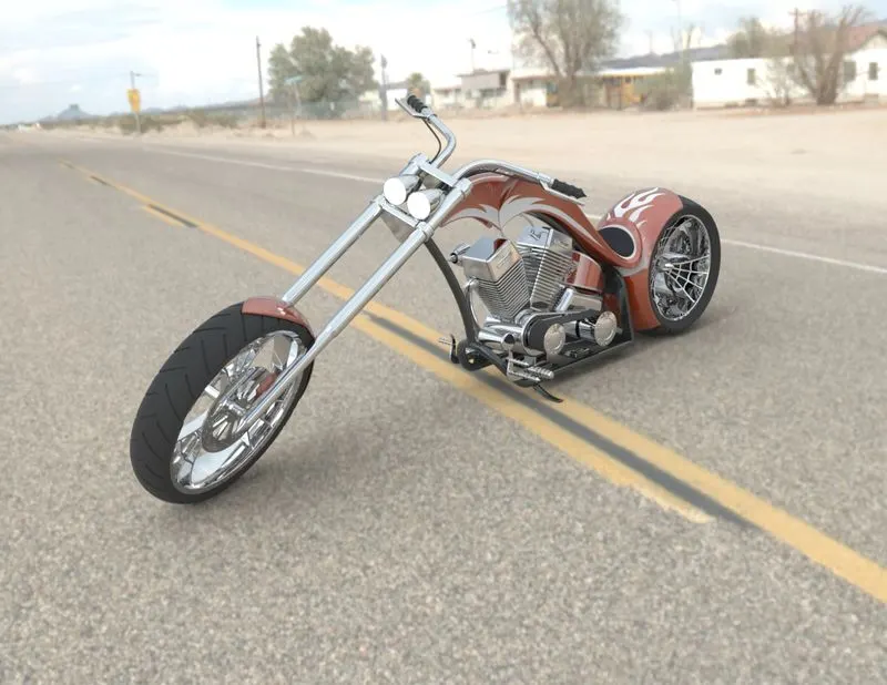
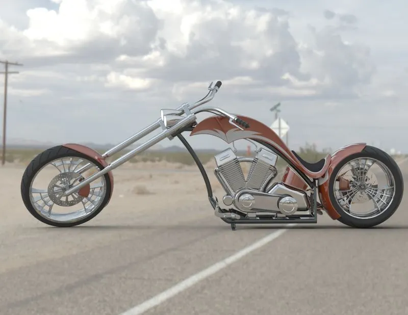
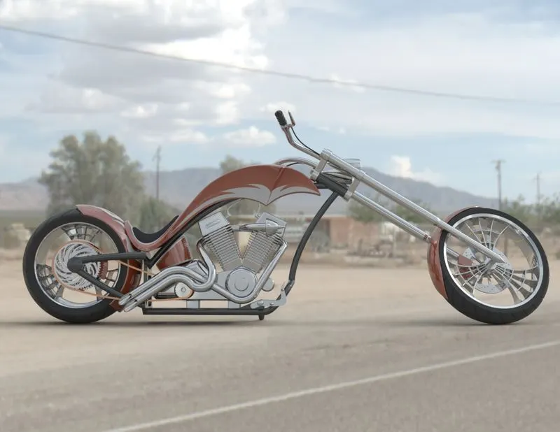
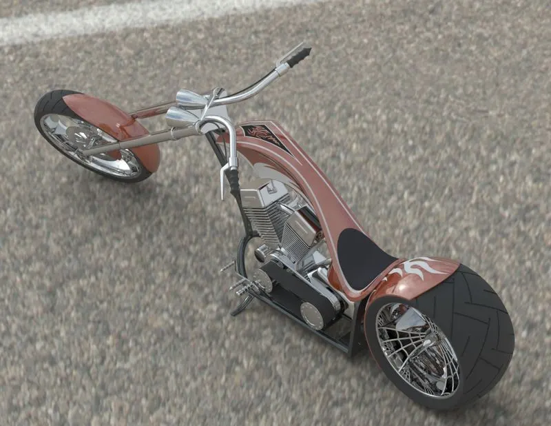
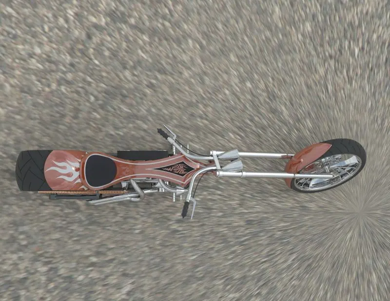
After making all these changes, we click on the Accurate render to initialize the rendering mechanism at an accurate level. The time for rendering depends entirely upon the no of passes given. More the no of passes more will be the time taken to complete rendering process.
ASSEMBLY IMAGE FILES:
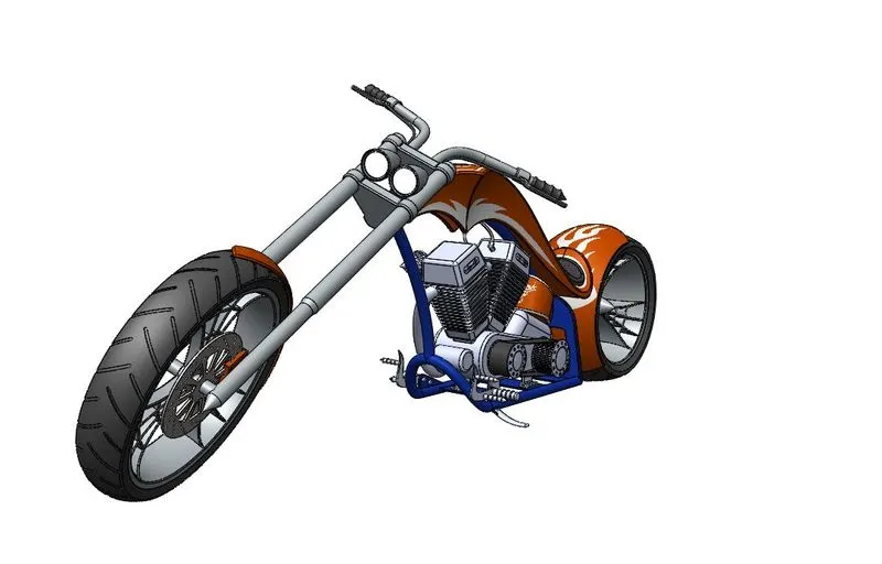
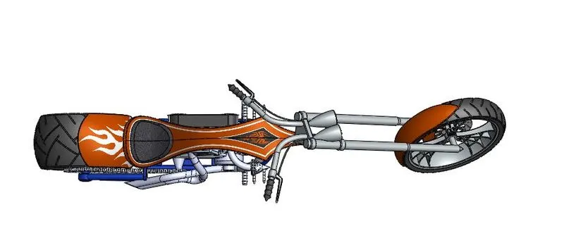
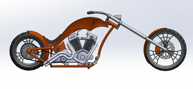
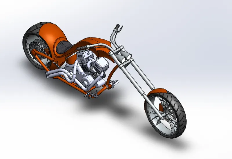
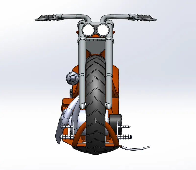
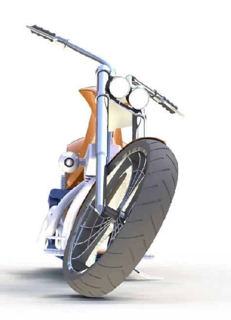
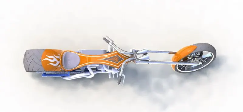
RENDERED IMAGE FILES INSIDE SOLIDWORKS
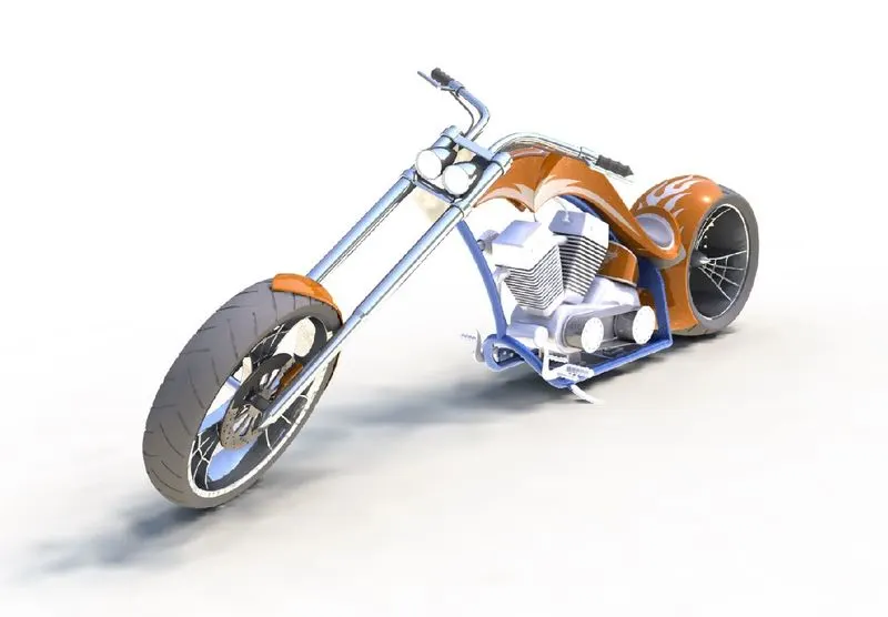
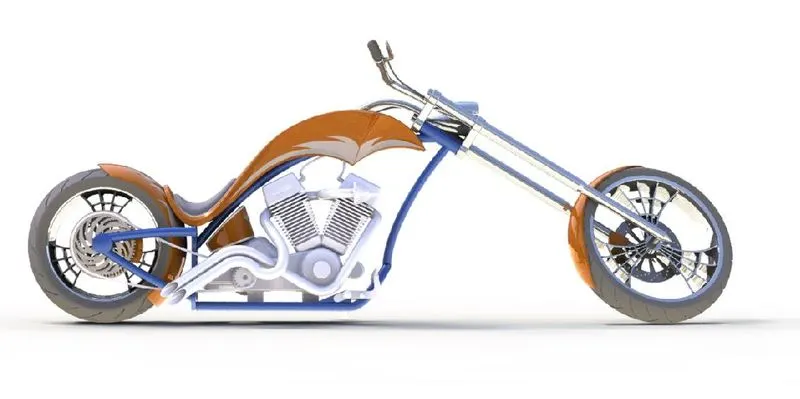
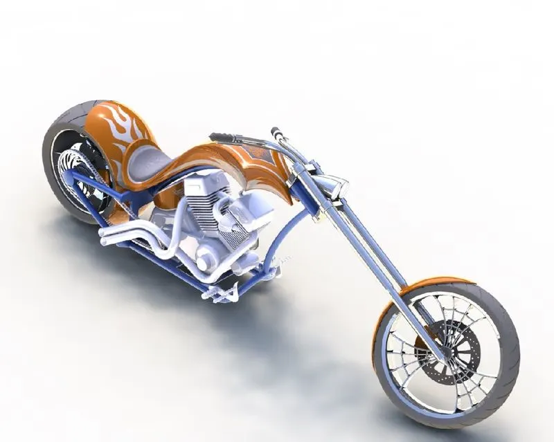
RENDERED IMAGE FILES USING VISUALIZE 2018
CONCLUSION:
Hence the following objectives had been achieved successfully and the required model is designed and rendered in SolidWorks.
- Created individual parts of an American Chopper bike using SolidWorks.
- Assembled all those individual parts into the bike titled “American Chopper”
- Understood the methods of applying decals, lights and camera.
- Generated a photorealistic model and render that using photoview 360 and SolidWorks Visualize.