Radar Mast & Final Assembly of Yacht
A Project Report
on
SOLIDWORKS - MODELLING & RENDERING OF AN SUNSEEKER PREDATOR YACHT
Done by
R.PRAKASH
TABLE OF CONTENTS
|
S.NO |
TITLE |
|
||||||||
|
1. |
INTRODUCTION |
|||||||||
|
1.1. |
OBJECTIVES |
|||||||||
|
1.2 |
METHODOLOGY |
|||||||||
|
2. |
PART MODELLING IN SOLIDWORKS |
|||||||||
|
2.1 |
PROPELLOR |
|||||||||
|
2.1.1 |
SKETCH |
|||||||||
|
2.1.1.1 |
STRAIGHT LINE |
|||||||||
|
2.1.1.2 |
SPLINE |
|||||||||
|
2.1.1.3 |
3 POINT CORNER RECTANGLE |
|||||||||
|
2.1.1.4 |
STRAIGHT LINE TO ARC |
|||||||||
|
2.1.2 |
REVOLVE BOSS/BASE |
|||||||||
|
2.1.3 |
INSERTING NEW OFFSET PLANE |
|||||||||
|
2.1.4 |
LOFTED BOSS/BASE |
|||||||||
|
2.1.5 |
FILLET |
|||||||||
|
2.1.6 |
EXTRUDE CUT |
|||||||||
|
2.1.7 |
CIRCULAR PATTERN |
|||||||||
|
2.1.8 |
APPEARANCE |
|||||||||
|
2.1.9 |
PROCEDURE |
|||||||||
|
2.2 |
RADAR |
|||||||||
|
2.2.1 |
SKETCH |
|||||||||
|
2.2.1.1 |
OFFSET ENTITIES |
|||||||||
|
2.2.1.2 |
CIRCLE |
|||||||||
|
2.2.1.3 |
POLYGON |
|||||||||
|
2.2.1.4 |
PLACING THREE POINTS |
|||||||||
|
2.2.2 |
EXTRUDE BOSS/BASE |
|||||||||
|
2.2.3 |
SKETCH DRIVEN PATTERN |
|||||||||
|
2.2.4 |
MIRROR |
|||||||||
|
2.2.5 |
ADDING TEXT ON RADAR |
|||||||||
|
2.2.6 |
SPLIT LINE |
|||||||||
|
2.2.7 |
APPEARANCES |
|||||||||
|
2.2.8 |
PROCEDURE |
|||||||||
|
2.3 |
BLUEPRINT |
|||||||||
|
2.3.1 |
INTRODUCTION |
|||||||||
|
2.3.2 |
PROCEDURE |
|||||||||
|
2.4 |
HULL |
|||||||||
|
2.4.1 |
INTRODUCTION |
|||||||||
|
2.4.2 |
INSERTING “BLUEPRINT SETUP FILE” INSIDE HULL PART |
|||||||||
|
2.4.3 |
SKETCH |
|||||||||
|
2.4.3.1 |
SPLINE |
|||||||||
|
2.4.3.2 |
CENTERLINES |
|||||||||
|
2.4.3.3 |
TRIM ENTITIES |
|||||||||
|
2.4.3.4 |
STRAIGHT SLOT |
|||||||||
|
2.4.3.5 |
3D SKETCH |
|||||||||
|
2.4.3.6 |
FILLET INSIDE SKETCH |
|||||||||
|
2.4.3.7 |
ELLIPSE |
|||||||||
|
2.4.3.8 |
MIRRORING INSIDE SKETCH |
|||||||||
|
2.4.4 |
PROJECTED CURVE |
|||||||||
|
2.4.5 |
SURFACE LOFT |
|||||||||
|
2.4.6 |
TRIM SURFACE |
|||||||||
|
2.4.7 |
SURFACE EXTRUDE |
|||||||||
|
2.4.8 |
KNIT SURFACE |
|||||||||
|
2.4.9 |
SURFACE FILL |
|||||||||
|
2.4.10 |
SHELL |
|||||||||
|
2.4.11 |
LINEAR PATTERN |
|||||||||
|
2.4.12 |
SWEEP |
|||||||||
|
2.4.13 |
DOME |
|||||||||
|
2.4.14 |
CURVES – HELIX/SPIRAL |
|||||||||
|
2.4.15 |
DELETING FACE |
|||||||||
|
2.4.16 |
COMBINE |
|||||||||
|
2.4.17 |
THIN CUT EXTRUDE |
|||||||||
|
2.4.18 |
SPLIT |
|||||||||
|
2.4.19 |
CHAMFER |
|||||||||
|
2.4.20 |
APPEARANCE |
|||||||||
|
2.4.21 |
PROCEDURE |
|||||||||
|
2.5 |
FRONT SEAT |
|||||||||
|
2.5.1 |
SURFACE SWEEP |
|||||||||
|
2.5.2 |
APPEARANCE |
|||||||||
|
2.5.3 |
PROCEDURE |
|||||||||
|
2.6 |
MIDDLE SEAT |
|||||||||
|
2.6.1 |
APPEARANCE |
|||||||||
|
2.6.2 |
PROCEDURE |
|||||||||
|
2.7 |
REAR SEAT |
|||||||||
|
2.7.1 |
SKETCH |
|||||||||
|
2.7.1.1 |
CORNER RECTANGLE |
|||||||||
|
2.7.2 |
SURFACE OFFSET |
|||||||||
|
2.7.3 |
RULED SURFACE |
|||||||||
|
2.7.4 |
SURFACE EXTEND |
|||||||||
|
2.7.5 |
APPEARANCE |
|||||||||
|
2.7.6 |
PROCEDURE |
|||||||||
|
2.8 |
SUPERSTRUCTURE |
|||||||||
|
2.8.1 |
SKETCH |
|||||||||
|
2.8.1.1 |
SPLIT ENTITIES |
|||||||||
|
2.8.1.2 |
CENTERPOINT ARC |
|||||||||
|
2.8.2 |
THICKEN THE SURFACE |
|||||||||
|
2.8.3 |
PROCEDURE |
|||||||||
|
2.9 |
RADAR MAST |
|||||||||
|
2.9.1 |
APPEARANCE |
|||||||||
|
2.9.2 |
PROCEDURE |
|||||||||
|
3. |
ASSEMBLY IN SOLIDWORKS |
|||||||||
|
3.1 |
INSERTING COMPONENTS |
|||||||||
|
3.2 |
MATE |
|||||||||
|
4. |
RENDERING USING SOLIDWORKS PHOTOVIEW 360 |
|||||||||
|
4.1 |
APPLYING DECALS & LIGHTS INSIDE SOLIDWORKS USING PHOTOVIEW 360. |
|||||||||
|
4.1.1 |
ADDING DECALS TO FLOOR SURFACES OF THE HULL, FLOOR SURFACE OF THE GARAGE AND THE FLOOR SURFACE ALONG STEPS |
|||||||||
|
4.1.2 |
ADJUSTING COLORS AND EDITING MATERIALS |
|||||||||
|
4.1.3 |
ADDING LIGHTS AND BACKGROUND IMAGES |
|||||||||
|
4.1.4 |
RENDERING LIGHTS |
|||||||||
|
4.2 |
CAMERA SETUP AND SCENE CREATION |
|||||||||
|
4.2.1 |
CREATING CAMERAS |
|||||||||
|
4.2.2 |
CHANGING THE SCENE COMPOSITION |
|||||||||
|
4.2.3 |
FINAL RENDERING |
|||||||||
|
5. |
RENDERING USING SOLIDWORKS VISUALIZE |
|||||||||
|
5.1. |
SETUP AND SCENE CREATION |
|||||||||
|
5.2. |
FINAL RENDERING |
|||||||||
- INTRODUCTION:
Solidworks is a CAD software used to carry out solid modelling and computer aided engineering activities. A French Software company by name “Dassault Systems” is the one who published it and works only on Microsoft Windows. Solidworks is used to model solids. Solidworks utilizes a parametric feature-based approach and it was initially developed by PTC (CREO/Pro – Engineer) to create models and assemblies.
Parameters – I refers to the constraints whose values determine the shape or geometry of the model or assembly.
Design intent – Is how the creator of the part wants to respond to changes and updates.
Features – It refers to the building blocks of part. They are the shapes and operations that construct a part.
Building a model in SolidWorks usually starts with a 2D sketch. The sketch consists of geometry such as points, lines, circles, arcs, splines and fillets. Dimensions are made in order to define the size and position of the geometry in a 2D plane. The dimensions in the sketch can be controlled independently, or by another parameter inside or outside the sketch.
- OBJECTIVE:
- To create individual parts of an Sunseeker Predator Yacht using SolidWorks
- To assemble all those individual parts into the bike titled “Sunseeker Predator Yacht”
- To generate a photorealistic model and render that using photoview 360 and SolidWorks Visualize.
- METHODOLOGY:
- Part Modelling in SolidWorks
- Assembly in SolidWorks
- Photo Realistic Rendering using SolidWorks Photoview 360 & SolidWorks Visualize 2018
- PART MODELLING IN SOLIDWORKS:
The 3D part is the basic building block of any large-scale design. A 3D part is an individual part of a big assembly of a machine or any other mechanical device. For example, if we consider a Refill pen as an assembly then its parts would be the refill casing, its lid, bottom and top cap for the refill casing and the refill itself. Each of these parts can be designed using solid works part modelling. As for the Sunseeker Predator Yacht, the following are the major parts & procedure which are included while designing the parts using Solidworks.
- Propellor
- Radar
- Blueprints
- Hull
- Front Seat
- Middle Seat
- Rear Seat
- Superstructure
- Radar Mast
- PROPELLOR:
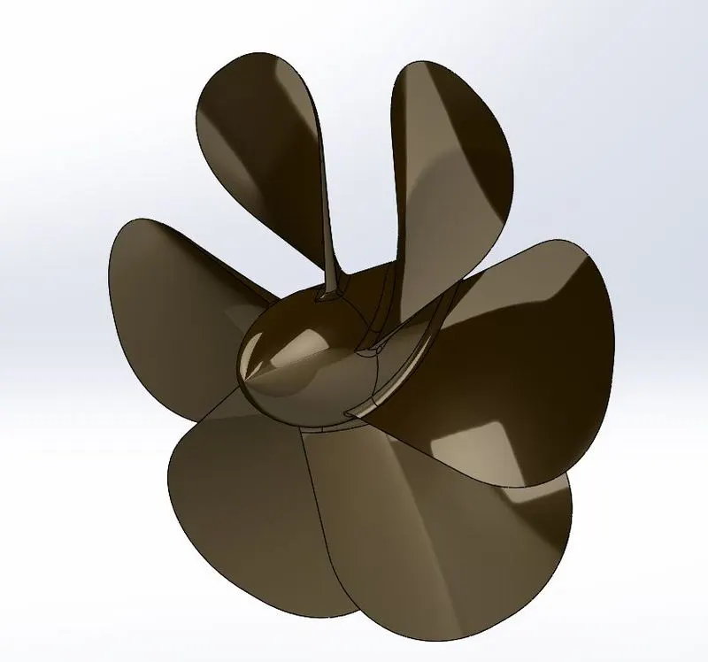
A propeller is a device with a rotating hub and radiating blades that are set at a pitch to form a helical spiral, that, when rotated, performs an action which is similar to Archimedies screw. It transforms rotational power into linear thrust by acting upon a working fluid, such as water or air
- SKETCH
The sketch tool is used to create 2D drawing of the part in Solidworks. The sketch is the basics of most 3D models. Creating a model usually begins with sketch. From the sketch, one can create features. We can combine one or more feature to make a part. Then, we combine and mate the appropriate parts to create an assembly. From the parts or assemblies, we can then create drawings.
A sketch is a 2D profile or cross section. To create a 2D sketch, we use a plane or a planer face. The following are some of the tools which are used in sketch while designing the transmission belt:
- Straight Line
- Spline
- 3 Point Corner Rectangle
- Straight Line to Arc
- STRAIGHT LINE:
The shortest distance between two points is said to be known as straight lines. Here in the design of Propellor, the straight line is used to create the 2D drawing.
- SPLINE:
Splines are used to draw complex curves. Solidworks supports two types of splines, B-splines and style splines. We can use B-splines to create complex curves. One can define and modify them using several controls including spline points, spline handles and control polygons.
- 3 POINT CORNER RECTANGLE:
The 3-point rectangle tool can be used for quickly drawing rectangles at an angle. One can also specify the default corner size for drawing rectangles and squares.
- STRAIGHT LINE TO ARC:
The straight line is then converted to an arc and is drawn for the required size. This is done by simply dragging the cursor back to the original point and then moving it outward, thus creating an arc.
- REVOLVE BOSS/BASE:
This feature is used to create a solid or surface geometry by revolving an entity along the center axis or any other selected entity which lays along the center of the revolving path.
- INSERTING NEW OFFSET PLANE:
Any time we create a 2D sketch in SOLIDWORKS we have to start that sketch on a plane or a planer surface. Since we will not always have a planer surface to sketch on, we have to become proficient in creating planes since it is crucial to modeling efficiently.
Hence this tool will help in inserting a new plane at defined position inside Solidworks.
- LOFTED BOSS/BASE:
The loft feature is an important tool for (surface) modeling in SolidWorks. The loft feature creates a shape by making transitions between multiple profiles and guide curves. This tool is very valuable for modeling complex surfaces.
- FILLET:
The fillet is used to create rounded internal or external face on the part. We can fillet all edges of a face, selected sets of faces, selected edges or edge loop.
- EXTRUDE CUT:
Extrude cut is feature tool which used to removal of material from solid model, by extruding a closed profile in one or two directions. This feature is located in both features command manager and Solidworks menu bar. Extrude cut feature tool is only applicable after creating a 3D model or design using Extrude Boss/Base tool. Its main function is removal of material from the design.
Like Extrude boss/base feature, Extrude cut also have “Cut property manager” which controls the extrusion cutting completely. In the cut property manager, you can control the direction of cut, cut extrusion length (in mm), start condition, end condition, applying draft for cut and thin feature cutting also.
- CIRCULAR PATTERN:
We can use circular patterns to create multiple instances of one or more features that you can space uniformly around an axis. The Circular Pattern Property Manager appears when you pattern one or more features around an axis. You can create circular patterns symmetrically or asymmetrically in both directions from the seed geometry. This is useful when the seed is not located at the end of the pattern arc.
- APPEARANCE:
The appearance is used to improve the aesthetic looks of the product and also it helps to make the product to look real. Solidworks is having a library of materials from which one can select the required one and is based on the type of product being designed.
- PROCEDURE:
- Open SolidWorks software – click on new – click “part” in new Solidworks document window – click “ok”.
- Click on Right plane – click on “sketch”.
- Click “straight line” – Draw a straight line to the right and to of origin
- Click on spline and join the two points
- Create a revolve base
- On top plane draw a 3 Point Rectangle
- Create a New Reference Plane at 360mm from Top Plane
- Create another 3-point rectangle on this new plane.
- Create a lofted Boss/Base between the two sketches.
- Make sure that the green balls are both in the same rectangle corner and blue circle details
- Create fillets on the edges of the loft.
- Create a new sketch on the blue surface of the axle.
- Create an extrude cut from the new sketch.
- Create a fillet on the edge of the blade.
- Create fillet along the edges of the axle and blade.
- Create a circular pattern.
- Change the color of the propeller.
- Save the file as Propeller.
2.2. RADAR:
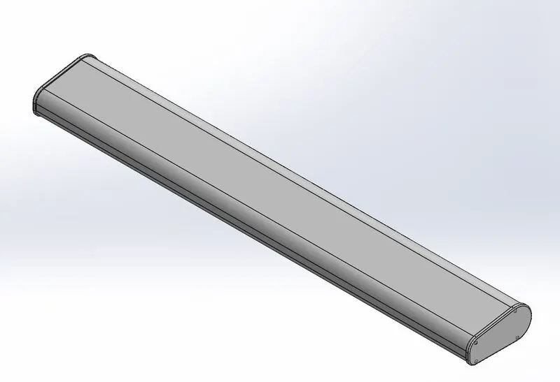
Radio Detection and Ranging, is used to detect objects and their position relative to your current location. ... A marine radar device acts as a major navigation aid for boaters. It helps in detecting boats, birds, landmasses, and weather systems - even if the visibility is less than usual.
- SKETCH:
The sketch tool is used to create 2D drawing of the part in Solidworks. The sketch is the basics of most 3D models. Creating a model usually begins with sketch. From the sketch, one can create features. We can combine one or more feature to make a part. Then, we combine and mate the appropriate parts to create an assembly. From the parts or assemblies, we can then create drawings.
A sketch is a 2D profile or cross section. To create a 2D sketch, we use a plane or a planer face.
The following are some of the tools which are used in sketch for the creating the RADAR :
- Offset Entities
- Circle
- Polygon
- Placing Three Points
- OFFSET ENTITIES:
Offset entities, takes a copy of your existing geometry and copies it at an offset. Instead of recreating geometry, you can use this to quickly sketch based on model geometry. Offset entities is a great tool for enlarging or shrinking your sketch geometry. Although most will use the tool with closed contour geometry, in this Video Tech Tip we use it for open contour lines.
- CIRCLE:
A circle is a closed two-dimensional figure in which the set of all the points in the plane is equidistant from a given point called “center.”
- POLYGON:
A Polygon is used to create polygon type entities inside the sketch of Solidworks.
- PLACING THREE POINTS
The position of a point in engineering drawing is defined with respect to its distance from the three principle planes i.e., with respect to the VP, HP, & PP. The point is assumed to be in the respective quadrant.
- EXTRUDE BOSS/BASE:
This feature is used to create solid material and hence helping us to view the 3D picture of the product. It is created from the sketch which is drawn previously.
- SKETCH DRIVEN PATTERN:
The Sketch Driven Pattern tool is an underused, but very useful tool. Typically, when we pattern items in SOLIDWORKS we tend to use linear or circular patterns, but what happens when we want to pattern an item where the spacing between instances is irregular or random? That’s where the Sketch driven pattern tool comes into its own
- MIROR:
This tool is used to create an opposite-hand version of a sketch, part or assembly component, which is positioned symmetrically about a plane.
- ADDING TEXT ON RADAR:
One can use stick fonts when applying sketch text to parts or assemblies for
laser engraving, water jet, and for Computer Numerical Control (CNC) machining.
- SPLIT LINE:
The SOLIDWORKS Split Line tool is used to project an entity (sketch, solid, surface, face, plane, or surface spline) onto other surfaces or curved/planar faces. You are also able to split faces on multiple bodies with one command.
- APPEARANCE:
The appearance is used to improve the aesthetic looks of the product and also it helps to make the product to look real. Solidworks is having a library of materials from which one can select the required appearance and is based on the type of product being designed.
- PROCEDURE:
- Open SolidWorks – Create a new part by going to File – New – Part. Select the three planes in the feature tree and make them visible by clicking on glasses, Go to File – Save as, Name the part as “RADAR”.
- Create a new sketch on Right Plane.
- Create an extrude for a depth of 700mm.
- Create a fillet for 46mm radius.
- Create another fillet for 20mm.
- Create another fillet for 30mm.
- Offset the outer edges of the radar.
- Extrude it outward for 10mm.
- Offset the outer edges of the newly created part towards inward direction to about 10mm and convert it into a construction line.
- Draw a circle of 8mm at a distance of 60mm vertically from the origin onto the construction line.
- Extrude this circle in outward direction to about 3mm.
- Create a fillet on to that circle outer edges for a radius of about 3mm.
- Click the center surface of the newly filleted part and click sketch – draw a polygon for a width of 3.50mm on each sides.
- Extrude that polygon outwardly for a depth of 1.5mm.
- Select the entire side surface of the radar and create a new sketch – Draw three points as per the dimensions given.
- Create a Sketch Driven Pattern using that points.
- Create a fillet along the outer edges at the sides of the radar for a radius of 3mm.
- Mirror the radar by selecting Insert – Pattern/Mirror – Mirror – then select right plane as Mirror Face – Select Bodies to Mirror option – Click on the radar – Enable Merge Results – Enable Knit Surfaces – Enable Propagate Visual Properties – Click ok.
- Now select the blue bottom surface and click on 2D sketch to create a new sketch – Draw a circle of radius 60mm at a horizontal distance of 710mm from left side of radar and at vertical distance of 80 mm from origin.
- Cut Extrude that circle by clicking on Insert – Cut Extrude or by clicking on Cut Extrude icon – Change the depth to 40mm – Click ok.
- Create a fillet along the outer and inner edges of the extrude cut circle for a radius of about 3mm.
- Create a 2D sketch along the front side of the radar – draw a construction line for the given dimension – add a text on the radar by selecting Tools – Sketch Entities – Text – Click on the horizontal centerline as reference curve – Type the required text in the Text Box – click on font button – Change the font to Century Gothic – Select the font style to Bold – Change the text height to 60mm – Click ok.
- Create Split Lines of the text by – Selecting Insert – Curve – Split Line or click on Split Line – select ‘Projection’ option – select ‘sketch 7 (current sketch) – as Sketch to Project – Select the two blue surfaces as Face to split – select the direction as ‘Single Direction’ option – Click ok.
- Change the color of the Radar to white.
- Change the color of the text to the custom RGB Color given by 70, 70, 70 – click ok.
- Save the file as Radar.sldprt.
- BLUEPRINT: -
- INTRODUCTION:
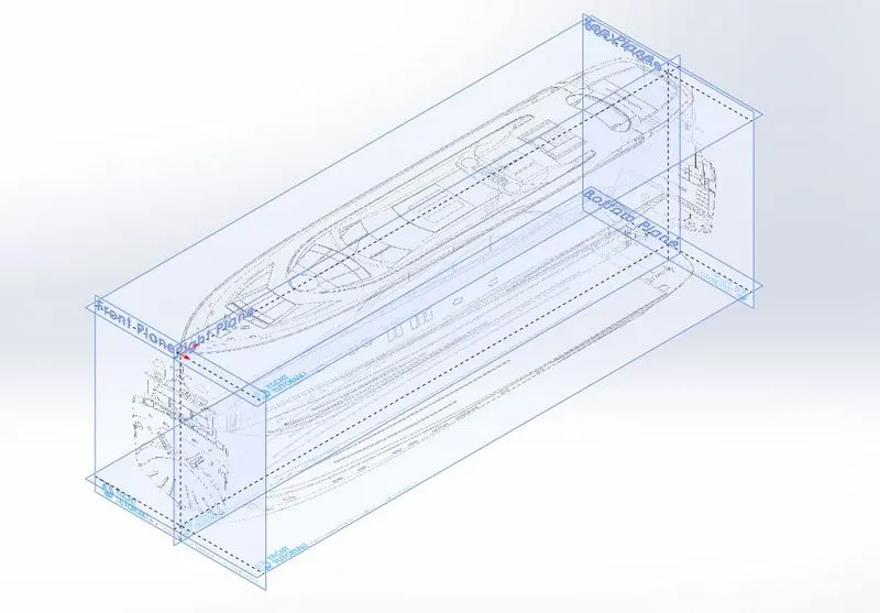
Blueprints are one of the most useful things for modelling an yacht using any 3D software. They are basically orthogonal drawings of the yacht in every direction (front, top, side and rear). They allow us to draw curves over a picture so that we can be precise and match the real shape of the yacht.
- PROCEDURE:
- Download the blueprint for the Yacht.
- Create a new Part.
- Create a new sketch in the Front Plane and import the Blueprint_Frontview.
- Change the dimensions and the position of the blueprint.
- Change the name of sketch 1 as Blueprint_Frontview.
- Similarly insert all the other images into their respective planes.
- HULL:
- INTRODUCTION:
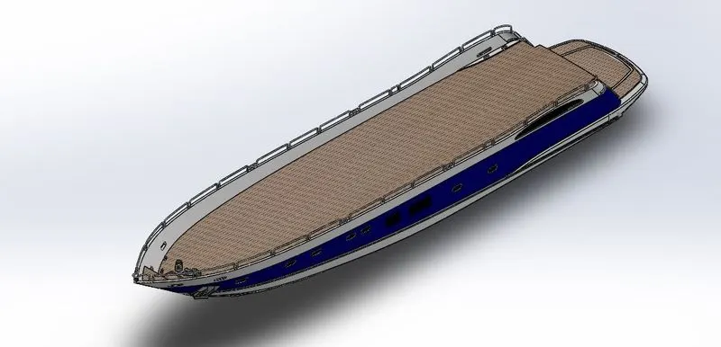
A hull is the watertight body of a ship, boat, or flying boat. The hull may open at the top, or it may be fully or partially covered with a deck. Atop the deck may be a deckhouse and other superstructure, such as a funnel, derrick, or mast. The line where the hull meets the water surface is called the waterline.
- INSERTING “BLUEPRINT SETUP FILE” INSIDE HULL PART
A blueprint is a guide for making something — it's a design or pattern that can be followed. The literal meaning of a blueprint is a paper — which is blue — with plans for a building printed on it. We can also call other guides or plans blueprints for example, here we call the front, top, bottom, side and backside views of the yacht as the blueprint of yacht.
Before going into the design of hull, it is required to bring in the blueprint of the entire yacht which had been arranged in a orderly manner in previous steps. This will reduce a considerable amount of time while carrying out the design. The procedure for inserting the blueprint is given under the “Procedure” heading.
- SKETCH:
The sketch tool is used to create 2D drawing of the part in Solidworks. The sketch is the basics of most 3D models. Creating a model usually begins with sketch. From the sketch, one can create features. We can combine one or more feature to make a part. Then, we combine and mate the appropriate parts to create an assembly. From the parts or assemblies, we can then create drawings.
A sketch is a 2D profile or cross section. To create a 2D sketch, we use a plane or a planer face.
The following are some of the sketch tools which are used for constructing Rear Fender,
- SPLINE:
Splines are used to draw complex curves. Solidworks supports two types of splines, B-splines and style splines. We can use B-splines to create complex curves. One can define and modify them using several controls including spline points, spline handles and control polygons.
- CENTERLINES:
Centerlines are annotations that mark circle centers and describe the geometry size on drawings. Centerlines are annotations that mark circle centers and describe the geometry size on drawings. You can insert centerlines into drawing views automatically or manually. The SOLIDWORKS software avoids duplicate centerlines. If you dimension to a centerline, the extension lines are shortened automatically.
- TRIM ENTITIES
The Trim Entities tool is mainly used for removing unwanted parts or portions from the design sketch. For trimming, one must have coincident sketch parts with another. The Sketch Trim Entities also consists of “Extend Entities” tool, which help to extend or adjusting the lines. The trimming is like removing unwanted parts using sissors.
- STRAIGHT SLOT
The straight slots and arc slots are two main type’s slot sketching tools inside SolidWorks sketch. Like different rectangle/arc drawing methods, slot sketching tools contains 3 point and center point drawing methods.
- 3D SKETCH
In 3D sketching, a graphical space handle helps maintain the orientation while sketching on several planes. The space handle appears when the first point of a sketch entity is defined on a selected plane. Using the space handle, one can select the axis along which you want to sketch. One can create a 3D sketch with reference to XY, YZ, and ZX planes, axes, or surfaces
We can use 3D sketches in applications such as SOLIDWORKS Weldments to insert structural members along a 3D frame, for routing paths, and to reverse engineer meshes into solid parts
- FILLET INSIDE SKETCH
The Sketch Fillet tool trims away the corner at the intersection of two sketch entities to create a tangent arc. This tool is available for both 2D and 3D sketches.
- ELLIPSE:
Solidworks has a standard tool for drawing an ellipse. In fact, this tool is more than just drawing standard ellipses.
- MIRRORING INSIDE SKETCH:
You can mirror solids that contain patterns of features on a face, and the pattern will be updated on both sides. The pattern must be created before the solid is mirrored. The plane becomes a persistent mirror once you create geometry using the mirror. The mirror relationship is maintained when you use other 2D and 3D tools to edit your design. Mirrored components have a mirrored icon in the Structure Tree and maintain their mirror relationships when they are exported. Mirrored objects are created on the same layer as the original object. Mirrored points do not maintain their mirror relationship.
- PROJECTED CURVE
The projected curve is a tool which utilizes two different 2D curves on a 2D plane in order to obtain a 3D curve. This is obtained by drawing two 2D curves on two different perpendicular planes. When these two planes are projected perpendicular to each other, their meeting junction will make a curve which is nothing but a projected curve.
- SURFACE LOFT:
The loft feature in SOLIDWORKS allows us to generate complex geometry in a single feature. It does this by interpolating surfaces between various cross-sections of a model. These cross-sections can be sketches, faces, or edges. In the loft interface, these cross-sections are considered “Loft Profiles”. Because this SOLIDWORKS tool is interpolating surfaces to create geometry, it can be difficult to control the loft enough to produce the desired geometry.
- TRIM SURFACE:
Primarily used to cut away material from a surface, and provides two modes: Standard and Mutual. In Standard mode, a single selection is defined as a Trim Tool, and target surfaces are trimmed accordingly. In Mutual mode, multiple surfaces are trimmed with respect to each other. Examples of each mode are shown below.
Trim Surface is the go-to tool for trimming surfaces and removing information, and is exceptionally easy to use. Additionally, the unique capabilities of Mutual mode make Trim Surface the most efficient (and sometimes only) tool to use when modifying multiple surfaces with respect to one another.
- SURFACE EXTRUDE
Using the SOLIDWORKS Surface Extrude feature, we can extrude the boundary edges of a face of a solid body or edges of a surface body in a customized direction. When we run the Extruded Surface command, two things can happen: Either a sketch is active or preselected or no sketches exists. In case no sketches exist or is selected, a message in yellow color shows in the property manager window on the left.
- KNIT SURFACE
This is a simple tool where all we have to do is to select all the surfaces that we want. So, we can individually click on each one and it'll fill up the box, or we can select all of them, just by swiping over from left to right on our screen. Now as we do that, these two options became available, create solid and merge entities. That gives us the ability to turn this into solid geometry.
- SURFACE FILL
The Fill Surface is different from the other types of features like loft, boundary and sweep. The main thing that Fill is supposed to do is to fill an n-sided patch. The patch can be filled with tangency, curvature continuity or simple contact at the edges. The boundary around the Fill can be edges or 2d/3d sketches.
- SHELL
The shell tool hollows out a part, leaves open the faces you select, and creates thin-walled features on the remaining faces. If you do not select any face on the model, you can shell a solid part, creating a closed, hollow model. You can also shell a model using multiple thicknesses.
- LINEAR PATTERN:
The Linear Pattern is used when we need to pattern one or more features along one or two linear paths. For linear patterning, there is a parent pattern (base pattern) which is used to create the array of patterns in one or two dimensions. The patterns should follow the exact shape of the main pattern. If we do any changes in the base pattern, it will automatically update to other pattern shapes produced from the base patterns.
- SWEEP
The Sweep function within SolidWorks is a powerful command used for multiple purposes. Sweep is the one feature in Solidworks that helps sweep a closed profile along a closed or open path.
- DOME
The Dome feature is used to create a small bulge on to the surface of a part thus adding aesthetic looks to the part.
- CURVES – HELIX / SPIRAL
One can create a helix or spiral curve in a part which can be used as a path or guide curve for a swept feature, or a guide curve for a lofted feature.
- DELETING FACE
The delete face command within Solidworks CAD becomes integral to the modeling process when you are dealing with imported geometry and surfaces. It’s great for removing geometry or enabling edits to existing geometry with no feature history.
OPTIONS AVAILABLE FOR “DELETE FACE” COMMAND:
- Delete:This option will remove the selected faces, leaving a void where the face or faces existed previously. If a face is deleted from a solid body, a surface body will be created. This is the quickest way to transform a solid body to a surface body.
- Delete & Patch:This option deletes a face from a body and automatically patches the void. The edges adjacent to the deleted face will be extended and then trimmed, leaving a distinct edge.
- Delete & Fill:This option deletes the selected faces and replaces them with a single unbroken face. The fill also has the option for tangent fill. With this option selected, the filled face will use tangent edges. With the option cleared the replacement face will use contact edges.
Since the Delete Face Command isn’t on any standard toolbars, the easiest way to access it is to customize your interface and add it to the features ribbon. However, you can always access the command by searching for it with the Command Search.
- COMBINE
The Combine feature lives under Insert>Features>Combine. The common function allows you to add two bodies together, and keep the area that is common to them. To use this feature, we will select the common button, and then under Bodies to Combine, select the two bodies.
- THIN EXTRUDE
The Thin Feature tool takes the sketched profile and creates a constant thickness in the sketch plane. One good example of this is a hollow tube. Instead of creating two circles in the sketch, you can just sketch one and then specify the thickness within the Extrude.
- SPLIT:
The Split tool is used to separate a part into two or more bodies.
- CHAMFER
The chamfer tool creates a beveled feature on selected edges, faces, or a vertex.
- APPEARANCE
The appearance is used to improve the aesthetic looks of the product and also it helps to make the product to look real. Solidworks is having a library of materials from which one can select the required appearance and is based on the type of product being designed.
The appearance of the hull floor, Rear Steps and the garage door are modified by inserting a new patch of wooded floor. This improves the aesthetic look for the hull.
- PROCEDURE:
- Open SolidWorks-Insert Blueprint_Setup.prt and then save the file as Hull.
- Create a new sketch on the bottom plane – view it normally – draw a horizontal line – connect the endpoint of the line with the back plane – Give dimensions and make the sketch completely constraints.
- Draw the three-point spline with one mid-point and connect the endpoint of the spline.
- Hold the horizontal line and the spline, hold down the control button and select the Equal Curvature option – click ok.
- Add a vertical relation to the arrow on the left endpoint.
- Make the spline match the blueprint as perfect as possible.
- Create a new sketch in the midplane – Draw the straight line – add dimensions.
- Create the second part of the edge with the spline with two midpoints.
- Create the third part of the edge with the straight line.
- Connect the endpoints of the spline with a tangency relation.
- Transform the two 2D sketches into one 3D sketch thus creating a 3D Projected Curve
- Create a new sketch in midplane – Draw the straight line – connect the endpoint of the line with the Back Plane – Give dimensions to the straight line.
- Create the second part of the edge with a spline with one midpoint – change the dimension of the spline.
- Create a new sketch on the bottom plane.
- Connect the spline with sketch 3 – Create the required Projected Curve.
- Create a new sketch on the Back Plane – draw the required sketch
- Create another new sketch on the Midplane – draw the required sketch and give the needed dimensions.
- Create a lofted surface by going to Insert – Surface – Loft or click on the Surface Loft Icon – Click on the profile box – select Curve1and Curve2 – Make sure that the green balls are both on the same end – Click the guide curve box – Select Sketch5 and Sketch6 – Set Guide curves influence to “To Next Guide” – Click ok.
- Create new sketch in midplane – Draw the next projected curve and the lofted surface for the bottom of the hull.
- In a similar way create all the other surfaces, rails and the rear shafts for propellors – then mirror the entire hull about the midplane.
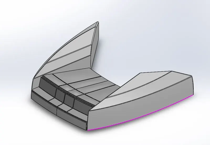
- FRONT SEAT:
Marine passenger seats and chairs can be used on the fast ferry, high-speed passenger ship, cruise ship, catamaran, crew boat, cargo ship, the sightseeing boat, traffic boat, pilot launch, yacht and other passenger vessels. The material of the seats adopts fire-proof leather, PU/PVC leather or fabric according to customer's requirements. The anti-corrosion aluminum structure is durable. The marine passenger seats and chairs are made according to ISO Standard and IMO Standard. They all have beautiful appearance and special design which makes people more comfortable when seating.
The following are some of the tools which are used to design the Front Seat of a Sun Seeker Predator Yacht in Solidworks.
- SURFACE SWEEP
Swept surfaces give you the tools to drag a given profile along a path to create a shape.
- APPEARANCE
The appearance is used to improve the aesthetic looks of the product and also it helps to make the product to look real. Solidworks is having a library of materials from which one can select the required appearance and is based on the type of product being designed.
The color of each part is modified accordingly with respect to the availability of the actual color in a real yacht.
- PROCEDURE
- Open SolidWorks and then open “Blueprint Setup.sldprt” file – then save this file as “Front Seat”.
- Import the deck surface of the hull as interface surface.
- Select the ‘deck surface’ and create a 2D sketch on it.
- Draw the required sketch as per the blueprint and try to match as perfectly as possible – Create a new plane by going to Insert menu – Reference Geometry – Plane or click on “New Plane” – for First Reference – Select the purple line – For Second Reference – Select the right endpoint of the spline – then click ok.
- Create a new sketch in this new plane – add dimensions.
- Create a surface sweep by going to – Insert – Surface sweep or clicking on Surface Sweep – Select the blue line as ‘Profile’ and then select the line as ‘Path’ – Click ok.
- Connect the two lines with surface sweep and also add “Pierce” relation to the two lines.
- Create a second surface extrude – then trim the surface – create a surface fill.
- Create a new 2D Sketch on the selected surface – draw the required sketch and then add dimensions – make the curves to match exactly with the blueprint – Trim the required surface.
- Create a new sketch on the Midplane – Trim the unwanted surface – create a lofted surface – Then once again trim the unwanted surface – Knit the surface – Fill the under side of the body – knit the two bodies of the front seat – create chamfer at one of the edges.
- Create a new sketch on one side of the seat – draw lines and add dimensions – Convert entities – Trim the upper part of the curve – Create Revolve Boss/Base – Select the corresponding axis of rotation – Change the direction angle to 10degrees – Select the purple region as selected contour – Click ok.
- Create a new sketch Top plane – draw the required sketch and then add dimensions – create an extrude cut – change the distance to 6000mm – Make sure that it is directed downward – if not click on the Reverse offset direction -click ok.
- Create a new sketch on the blue surface – Offset the entities to 5mm – should be directed upwards – click ok.
- In a similar way draw and design all the other required parts and create the required fillets.
- Create the required mirror – create the required dome.
- Change the color of the main bodies of the front seat to white.
- Change the color of the mattress bodies.
- Save the file as “Front Seat”.
- MIDDLE SEAT:
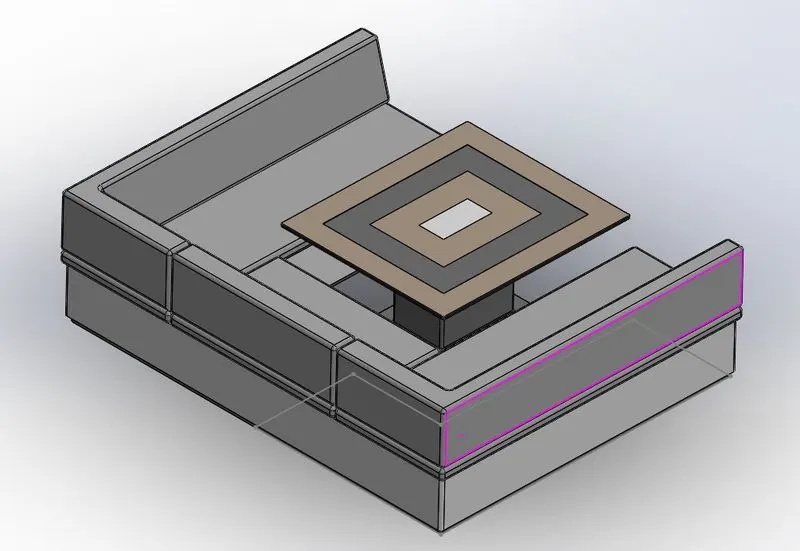
Marine passenger seats and chairs can be used on the fast ferry, high-speed passenger ship, cruise ship, catamaran, crew boat, cargo ship, the sightseeing boat, traffic boat, pilot launch, yacht and other passenger vessels. The material of the seats adopts fire-proof leather, PU/PVC leather or fabric according to customer's requirements. The anti-corrosion aluminum structure is durable. The marine passenger seats and chairs are made according to ISO Standard and IMO Standard. They all have beautiful appearance and special design which makes people more comfortable when seating.
- APPEARANCE
The Appearances command displays the colors of faces, features, bodies, and the part and is a shortcut to editing appearances. You can see the hierarchy of colors by expanding the command. Color selections made in the Appearances Property Manager supersede colors set on the Document Properties tab.
- PROCEDURE:
- Open Solidworks – open Blueprint Setup.sldprt – Save the file as – Middle Seat.
- Import the deck surface of hull as surface bodies.
- Select the deck surface for a new 2D sketch.
- Draw the required sketch as per the dimensions.
- Now create an extrude for 35 mm upward.
- Offset the edges of the blue surface.
- Trim the upper part of the offset lines.
- Create another extrude for a depth of 300mm upwards.
- Create a new offset plane at a distance of 5 mm from the top surface.
- Create a new 2D sketch on this new plane.
- Create another extrude for a depth of 70mm in the same upward direction.
- Create another new offset plane at a distance of 5mm above the surface of the extruded portion – Draw the required sketch and add dimensions – Create another extrude in upward direction for a depth of 350mm.
- Create required chamfer and fillets.
- Mirror the two main bodies of the middle seat.
- Mirror the two remaining bodies of the middle seat.
- Create required number of fillets.
- Design the center table in a similar manner.
- Change the color of middle seat to white.
- Change the color of the pillow to light grey.
- Change the color of the table to a custom grey by changing the RGB numbers to 120, 120, 120.
- Change the color of the table top to a custom light brown by changing the RGB number to 190, 169, 146.
- Change the color of the middle part of the table top to white.
- Change the color of the top and the bottom edges of the seat to a custom grey color by changing the RGB numbers to 120, 120, 120.
- Save the file as Middle Seat.
- REAR SEAT:
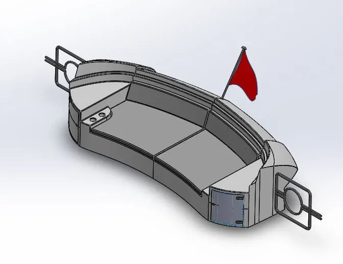
Marine passenger seats and chairs can be used on the fast ferry, high-speed passenger ship, cruise ship, catamaran, crew boat, cargo ship, the sightseeing boat, traffic boat, pilot launch, yacht and other passenger vessels. The material of the seats adopts fire-proof leather, PU/PVC leather or fabric according to customer's requirements. The anti-corrosion aluminum structure is durable. The marine passenger seats and chairs are made according to ISO Standard and IMO Standard. They all have beautiful appearance and special design which makes people more comfortable when seating.
- SKETCH
The sketch tool is used to create 2D drawing of the part in Solidworks. The sketch is the basics of most 3D models. Creating a model usually begins with sketch. From the sketch, one can create features. We can combine one or more feature to make a part. Then, we combine and mate the appropriate parts to create an assembly. From the parts or assemblies, we can then create drawings.
A sketch is a 2D profile or cross section. To create a 2D sketch, we use a plane or a planer face.
The following is the tool which is commonly used for designing the Rear Seat.
- CORNER RECTANGLE:
The corner rectangle is a simple sketch tool in which the rectangle is drawn initially from corner to corner. By clicking on a point inside sketch, the first corner of the rectangle is fixed and its diagonally opposite corner is dragged to the required size. Afterwards the dimensions are given to constrain the sketch.
- SURFACE OFFSET:
A common technique for advanced surfacing modeling is using the Surface Offset command. In SOLIDWORKS 2020, the command gives users the option to SEE and REMOVE any surfaces that cannot be offset, building the remaining geometry.
With this tool, all we have to do is select the face or surface body to offset all the edges, or manually select the edges you need. The tool can be found on the Sketch tab in the Command Manager, or by clicking Tools > Sketch Tools > Offset on Surface. This would require multiple steps that might involve converting entities, projecting sketches onto the face, creating 3D splines on surfaces, and the list goes on. Depending on our approach, there might even be some slight deviation between the offset we created and the actual edges of the original face or surface, which may not suit our needs.
- RULED SURFACE:
The Ruled Surface command is a very versatile command that can create several different types of surfaces. It will create surfaces at an edge relative to an existing surface. All it takes is just an edge and a user input distance. With that, the Ruled Surface can add new surface geometry in the following ways:
- Tangent to Surface
- Normal to Surface
- Tapered to Vector
- Perpendicular to Vector
- Sweep
- SURFACE EXTEND:
Extension of the surface is an operation that allows you to extend a surface by a given distance, to a point or to another surface. You can select the entire surface area or an edge / day. Depending on the geometric conditions, the operation will succeed or fail, this is especially true for high elongation values with complicated curvature. It is easy to recognize, because the preview disappears.
- APPEARANCE
The Appearances command displays the colors of faces, features, bodies, and the part and is a shortcut to editing appearances. You can see the hierarchy of colors by expanding the command. Color selections made in the Appearances Property Manager supersede colors set on the Document Properties tab.
- PROCEDURE:
- Open SolidWorks – Open Blueprint Setup.sldprt file – Save the file as Rear Seat.
- Import the deck surface of the hull as interface surface – Uncheck all the options except “Surface Bodies”
- Create a new sketch on the mid plane – draw the required sketch and add dimensions – Insert an new reference plane – Connect the spline and the sketch – Create surface sweep by going to Insert – Surface Sweep or click on Surface Sweep icon – Select Sketch1 as Profile and then Sketch2 as Path – Click ok.
- Create a surface offset for an offset distance of about 50mm.
- Trim the required surfaces.
- Create the required Ruled Surface by going to Insert – Surface – Ruled Surface – Select Tangent to surface – Change the ‘D’ value to 150mm – Click ok.
- Knit the required surfaces.
- Create a new plane – Convert the required entities – Insert an new plane – Create a 2D sketch – Create a surface sweep – Extend the surface of Surface-Sweep 2 by going to Insert – Surface – Extend or click on extend icon – Select edge 1 as Edges/Faces to Extend – Select Distance as End Conditions – Change D1 to 200mm – Select the same surface as Extension type – Click ok.
- Trim and knit the required surfaces.
- Create a surface extrude by going to Insert – Surface extrude – Change D to 1200mm – The direction of extrusion is upwards.
- Trim and knit the required surfaces.
- Create a 3D sketch by using Offset Entities – Create a surface loft.
- Follow the above same procedure to create the required Rear Seat using SolidWorks.
- SUPERSTRUCTURE:
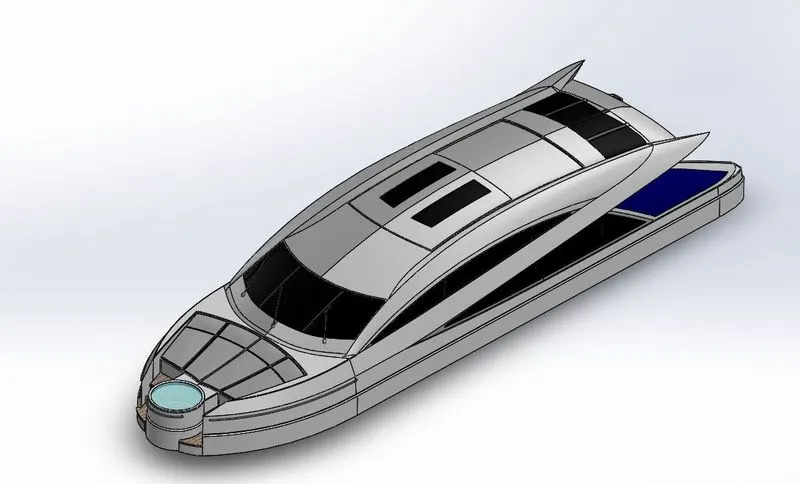
On water craft, the superstructure consists of the parts of the ship or a boat, including sailboats, fishing boats, passenger ships, and submarines, that project above her main deck.
The size of a watercraft's superstructure can have many implications in the performance of ships and boats, since these structures can alter their structural rigidity, their displacements, and/or stability. These can be detrimental to any vessel's performance if they are taken into consideration incorrectly.
The height and the weight of superstructure on board a ship or a boat also affects the amount of freeboard that such a vessel requires along its sides, down to her waterline. In broad terms, the more and heavier superstructure that a ship possesses (as a fraction of her length), the less the freeboard that is needed.
- SKETCH
The sketch tool is used to create 2D drawing of the part in Solidworks. The sketch is the basics of most 3D models. Creating a model usually begins with sketch. From the sketch, one can create features. We can combine one or more feature to make a part. Then, we combine and mate the appropriate parts to create an assembly. From the parts or assemblies, we can then create drawings.
A sketch is a 2D profile or cross section. To create a 2D sketch, we use a plane or a planer face.
The following are some of the tools which are used to design the Front Wheel of an American Chopper in Solidworks.
- SPLIT ENTITIES
The SOLIDWORKS Split Line tool is used to project an entity (sketch, solid, surface, face, plane, or surface spline) onto other surfaces or curved/planar faces. You are also able to split faces on multiple bodies with one command
- CENTERPOINT ARC
Solidworks provides various kinds of methods and commands to draw arcs inside it. This arc drawing command called Centerpoint Arc is one of them. The Centerpoint Arc tool is used to draw an arc by defining the center point, start point and endpoint
- THICKEN THE SURFACE:
Thicken takes a surface body (which has zero thickness) and makes it a solid (making it a volume) by specifying a thickness value and side to thicken. Until now, the calculation was based on surface normal, which is often what you want. Now, though, we can specify a direction for the offset created by the Thicken command.
- PROCEDURE:
- Open SolidWorks – Open Blueprint setup.sldprt file – save the file as ‘Superstructure’.
- Import the deck surface of the hull as interface surface.
- Create a new sketch on the deck.
- Unhide the top view of the blueprint – draw the sketch and add the required dimensions – create the surface extrude for 600mm – direction of extrusion is upwards.
- Create a new reference plane – Create a new sketch on this new plane – draw the required sketch and add the dimensions – create a 3D sketch – create a surface sweep.
- Knit the required surfaces.
- Create fillets on the required surfaces.
- Create a Ruled Surface by going to – Insert – Surface – Ruled Surface or click on the Ruled Surface Icon – Select Tapered to Vector option – Change the D to 500mm – Select the pink deck surface as Reference Vector – Change the angle to 5 degree – Select the four outer (blue) edges of the surface as edge section – Select the Trim and Knit option – Select the Connecting surface option – Make sure that the draft is directed inwards – If not use the Alternate Side option to switch the direction of each edge – click ok.
- Create a new sketch on midplane – draw and dimension the required sketch – Trim the required surfaces.
- Create another new sketch in midplane – draw and dimension the required sketch.
- Create another sketch on top plane – Use convert entities to bring in the sketch line of previously drawn part – Trim the ends of the converted edge.
- Create a projected curve.
- Create a new sketch on top plane – Offset the edge of the superstructure – Trim the end of the offset edge - Create another sketch on midplane – draw and dimension the required sketch – Create a projected curve using the two 2D Sketches.
- Repeat the above-mentioned steps to create the ‘Superstructure’ and the then finally change the appearance of the part as required.
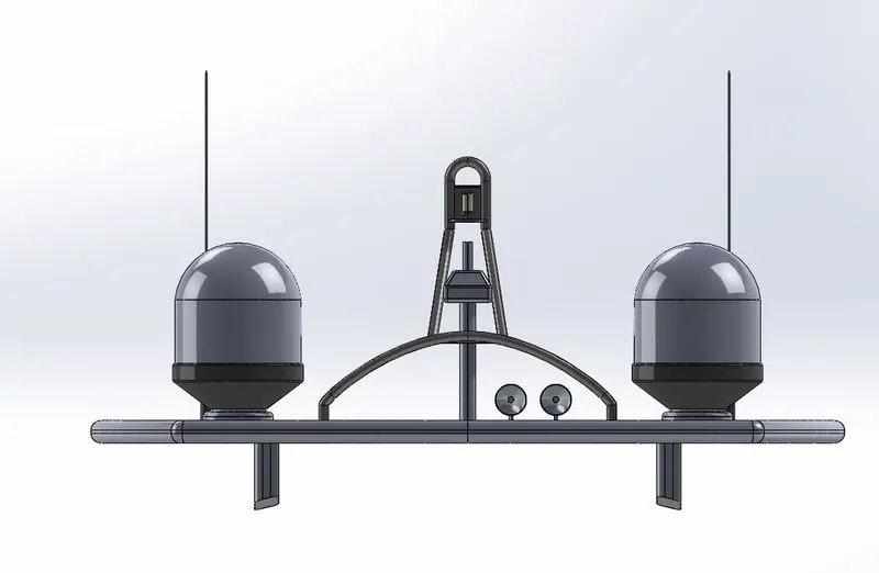
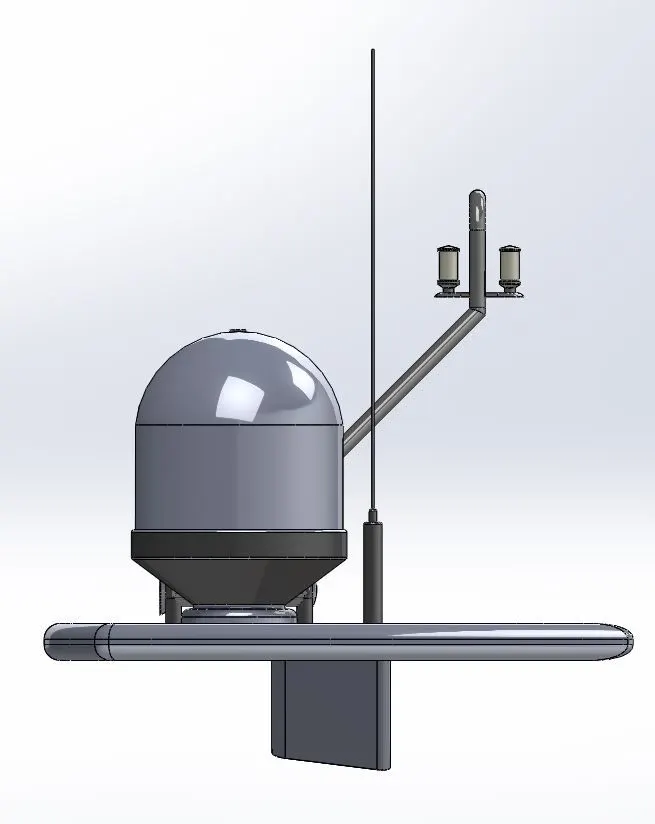
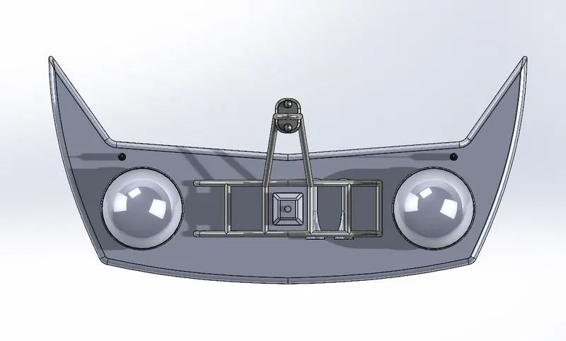
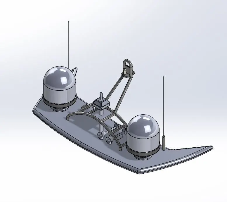
- RADAR_MAST:
Marine radars are X band or S band radars on ships, used to detect other ships and land obstacles, to provide bearing and distance for collision avoidance and navigation at sea. They are electronic navigation instruments that use a rotating antenna to sweep a narrow beam of microwave around the water surface surrounding the ship to the horizon, detecting targets by microwaves reflected from them, generating a picture of the ship's surroundings on a display screen.
Radar is a vital navigation component for safety at sea and near the shore. Captains need to be able to maneuver their ships within feet in the worst of conditions and to be able to navigate "blind", when there is no visibility at night or due to bad weather. In addition to vessel-based marine radars, in port or in harbor, shore-based vessel traffic service radar systems are used by harbormasters and coast guards to monitor and regulate ship movements in busy waters.
- APPEARANCE
The Appearances command displays the colors of faces, features, bodies, and the part and is a shortcut to editing appearances. You can see the hierarchy of colors by expanding the command. Color selections made in the Appearances Property Manager supersede colors set on the Document Properties tab.
- PROCEDURE:
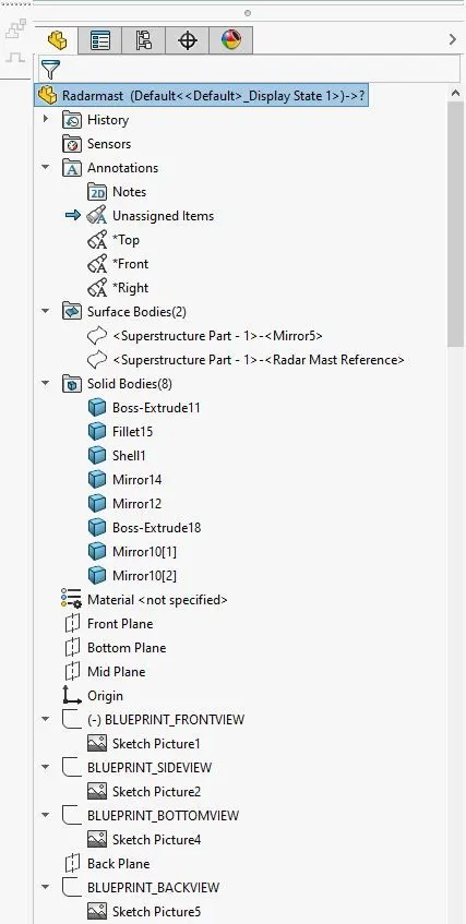
- Open SolidWorks – Open Blueprint Setup.sldprt file – Save the file as Radarmast.
- Import the Top Surface of the Superstructure as Interface surface – Uncheck all the options except the surface bodies options – click ok.
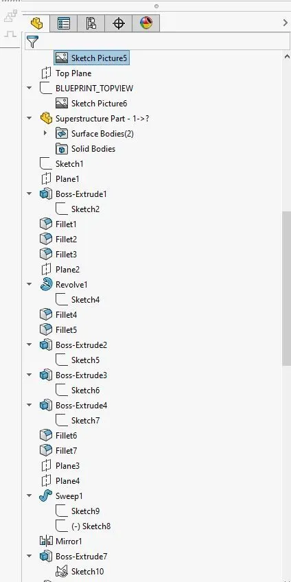
- Create a new sketch in the mid plane – draw and dimension the required sketch – Create a new plane – create a new 2D sketch in this new plane – draw and dimension the required sketch on this new plane – Create an extrude to a depth of 140mm in upward direction.
- Create required fillets.
- Create another new plane – Create a new 2D sketch on this new plane – draw and dimension the required sketch on this new plane – create a revolve by going to Insert – Boss/Base – Revolve or simply clicking on the Revolve icon – select the blue line as the axis of revolution – click ok.
- Create the required fillets.
- Create a new sketch on the blue surface – draw and dimension the required sketch on this surface – Create a solid extrude for a depth of 345mm which should be directed upwards.
- Create another sketch on the blue surface – Draw the required sketch and add dimensions – create another extrude for a depth of 50mm which is directed upwards – Create the required fillet.
- Create another new plane – Create a 2D sketch on this new plane – draw and dimension on this new plane – Exit sketch – Create another new plane – Create an 2D sketch on this new plane – draw and dimension on the new plane – create a solid sweep.
- Mirror the Sweep by going to Insert – Pattern/Mirror – Mirror or click on the mirror icon – Select Plane2 in the Feature Tree as “Mirror Face” – Select the Feature to Mirror option – Select Sweep1 – Click ok.
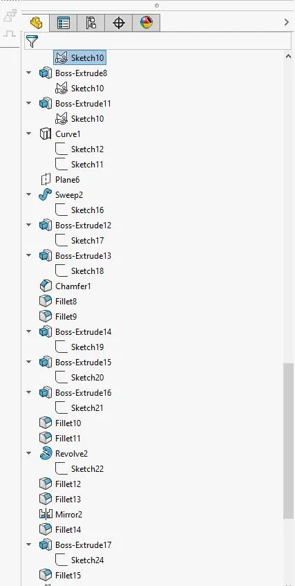
- Create a new sketch on new plane2 – draw and dimension the required sketch – Create an extrude towards midplane and change the offset distance to 500mm.
- Create a new sketch on midplane – draw and dimension the required sketch on to this plane – Create another sketch on created reference plane2 – draw and dimension onto this plane – Create a Projected Curve using the above mentioned two 2D Curves.
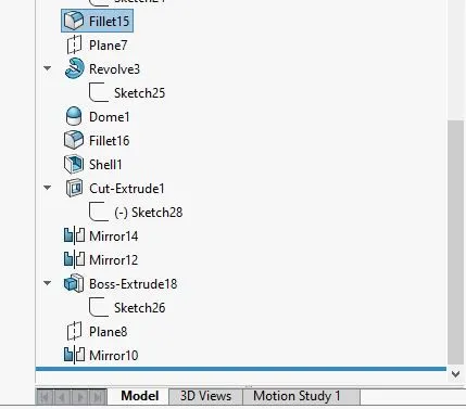
- Create another new sketch on the midplane – draw and dimension a circle of diameter 60mm onto this plane and make its center coincident with the newly generated 3D curve – Create a Solid Sweep using the circle as profile and the 3D curve as the path.
- After creating all the required components use the mirror option to create the other half of the Radarmast.
- Add the required color to the part and save the file as “Radarmast”.
- ASSEMBLY IN SOLIDWORKS:
One can build complex assemblies consisting of many components, which can be parts or other assemblies, called subassemblies. For most operations, the behavior of components is the same for both types. Adding a component to an assembly creates a link between the assembly and the component. When SOLIDWORKS opens the assembly, it finds the component file to show it in the assembly. Changes in the component are automatically reflected in the assembly. The document name extension for assemblies is sldasm.
The following are some of the tools which are used to during assembly of Sunseeker Predator Yacht.
- INSERTING COMPONENTS:
- Initially all the parts are opened inside Solidworks and then new assembly window is opened
- Into this window, starting from hull each part files are inserted
- MATE
Mates create geometric relationships between assembly components. Hence based on the components and their position, their corresponding mates are created
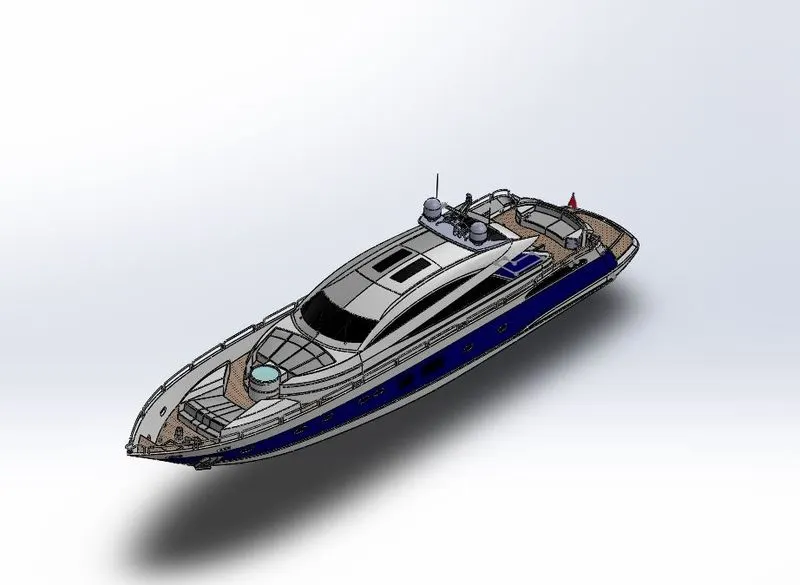
ASSEMBLY ISOMETRIC VIEW
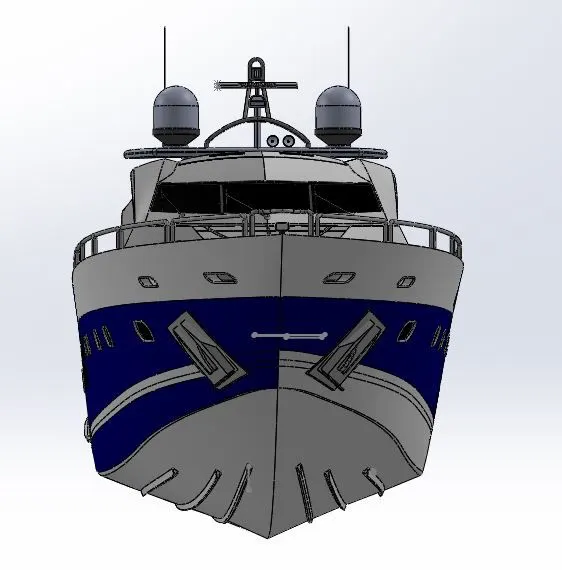
ASSEMBLY FRONT VIEW
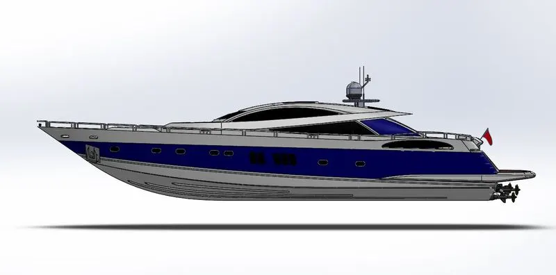
ASSEMBLY RIGHT SIDE VIEW
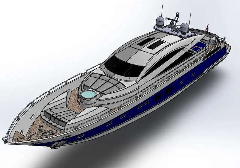
ASSEMBLY CAMERA VIEW
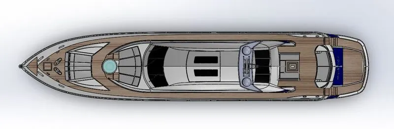
ASSEMBLY TOP VIEW
- RENDERING USING SOLIDWORKS PHOTOVIEW 360:
Rendering or image synthesis is the process of generating a or non photorealistic image from a 2D or 3D model by means of a computer program. The resulting image is referred to as the render. Multiple models can be defined in a scene file containing objects in a strictly defined language or data structure. The scene file contains geometry, viewpoint, texture, lightning, and shading information describing the virtual scene. The data contained in the scene file is then passed to a rendering program to be processed and output to a digital image or raster graphic image file. The term "rendering" is analogous to the concept of an artistis impression of a scene. The term "rendering" is also used to describe the process of calculating effects in a video editing program to produce the final video output.
- APPLYING DECALS & LIGHTS INSIDE SOLIDWORKS USING PHOTOVIEW 360.
Photoview 360 is a SolidWorks add-in that produces photo-realistic renderings of SolidWorks models. The rendered image incorporates the appearances, lighting, scene, and decals included with the model. Photoview 360 is available with SolidWorks Professional or SolidWorks Premium.
- ADDING DECALS TO FLOOR SURFACES OF THE HULL, FLOOR SURFACE OF THE GARAGE AND THE FLOOR SURFACE ALONG STEPS
Decals are the design prepared on special paper for durable transfer on to another surface such as glass or porcelain. Here the decals are applied onto the floor surfaces of the hull, floor surface of the garage and the floor surface along the steps.
- ADJUSTING COLORS AND EDITING MATERIALS
The colors for propellor, RADAR, Hull, Rear Seat, Middle Seat, Front Seat, Superstructure, and Radar mast are modified corresponding to one’s taste. The material is also modified correspondingly.
- ADDING LIGHTS AND BACKGROUND IMAGES:
The background images and lights are added corresponding to one’s likeness. Here we can change the lights and their position which we can fix it in position. Also, one can include different HD 3D image in the background.
- RENDERING LIGHTS
We can either suppress lights or enable them. They add luminescence to the 3D model. There are four available lights inside Solidworks
- Directional Lights
- Point Lights
- Spot Light &
- Sun Light.
For Sunseeker Predator Yacht, we choose Directional Lights.
- CAMERA SETUP AND SCENE CREATION:
The main reason for undergoing this step is to make sure that the model rendered might look realistic. As regards the Sunseeker Predator Yacht, its hull should touch the sea level. Also, the yacht should lean on one side so that the yacht may look real when rendered. These are the process which are carried out before going for rendering.
- CREATING CAMERAS:
The rendering will be looking more realistic if we add cameras to the view. This will make the 3D model more visible along the direction in which we want to view it. A camera can be added by selecting Main Menu – View – Lights and Cameras – Add Camera.
The camera can be turned along all three axis and it focal point can also be adjusted.
- CHANGING THE SCENE COMPOSITION:
To make the 3D model as realistic as possible, we add a 3D picture image and change the scene composition correspondingly. One should make sure of turning on the perspective view.
- FINAL RENDERING:
Under Render tools, if clicked on Render Preview – one can preview the rendered image inside Solidworks window. Any correction if required, can be made correspondingly. Also, a comparison can be made between previous rendered image and the recent one and hence it will help in coming to a conclusion while selecting an image which can be well rendered.
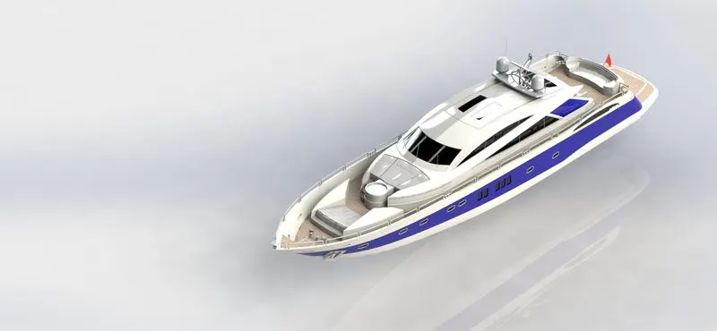
RENDERED ISOMETRIC VIEW USING PHOTOVIEW 360
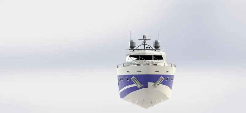
RENDERED FRONT VIEW USING PHOTOVIEW 360
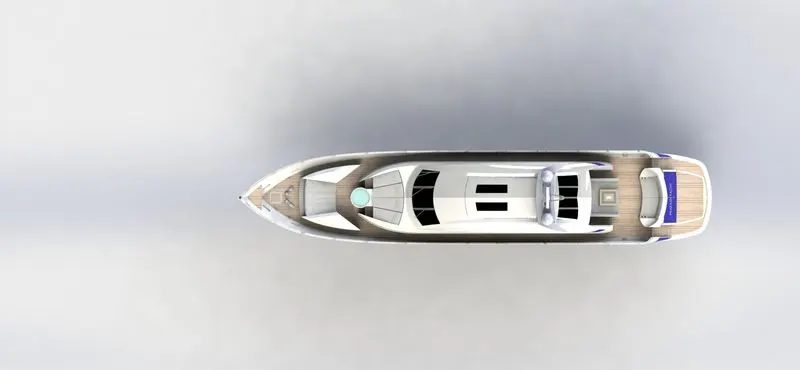
RENDERED TOP VIEW USING PHOTOVIEW 360
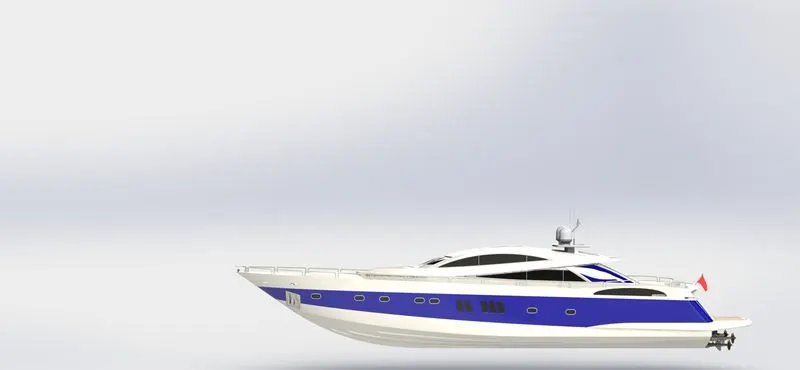
RENDERED SIDE VIEW USING PHOTOVIEW 360
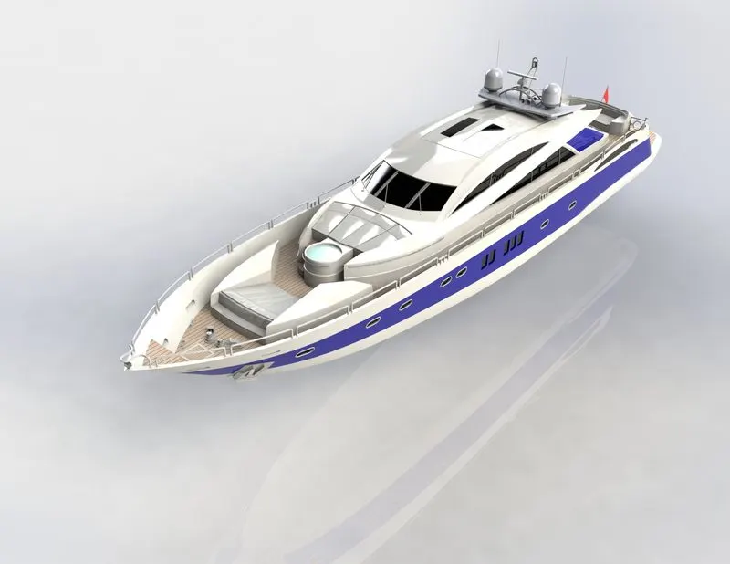
RENDERED CAMERA VIEW USING PHOTOVIEW 360
- RENDERING USING SOLIDWORKS VISUALIZE:
The Solidworks is a tool which is used to create Solidworks rendering. We import models into Solidworks visualize the we group them based on appearance or by different types of hierarchy or by entire assembly. After opening Solidworks visualize, click on new project – go to “Import models and parts” and then browse for “Assembly” of American chopper. Next open “Import Settings” and under Import Settings we have four tabs
- Geometry
- Appearances
- Environments
- Decals
Change the required parameters correspondingly.
- SETUP AND SCENE CREATION
Right click on new appearances and delete it. Go to “File Libraries” tab – here we can change the material, paint and scenes correspondingly instead of changing one by one parameters in appearance tab.
- FINAL RENDERING
After making all these changes, we click on the Accurate render to initialize the rendering mechanism at an accurate level. The time for rendering depends entirely upon the no of passes given. More the no of passes more will be the time taken to complete rendering process.
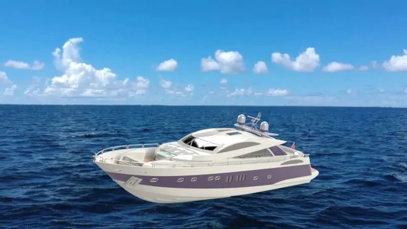
RENDERED BY SOLIDWORKS VISUALIZE
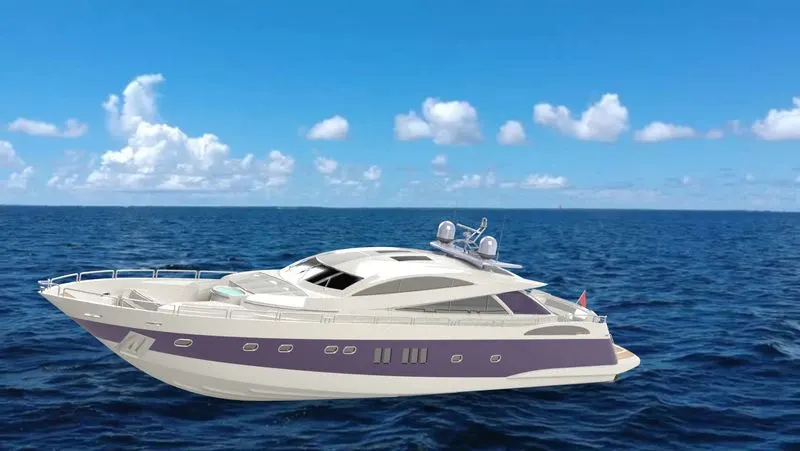
RENDERED BY SOLIDWORKS VISUALIZE
conclusion:
Thus the Sunseeker Predator Yacht had been successfully modelled and assembled using SolidWorks. Final Rendering is also carried out using Photoview 360 and Solidworks Visualize.