Advanced Sheet Metal Design Using NX Cad Challenge_7_ Metal bracket-II
DESIGN OF NX SHEET METAL BRACKET II
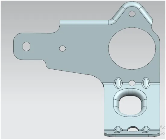
DESIGNED BY,
ASHIS TARAI
LINK:-
https://drive.google.com/file/d/15DUMUq5Q69CHgWv8swkrszn1icjLDYBe/view?usp=sharing
OBJECTIVE:-
- To Create a Sheet Metal Bracket II using various operations performed in NX sheet metal software using 2D drawing.
- To Analysis the given sketch and create a sheet metal part /bracket according to it.
INTRODUCTION:-
Siemens NX software is a flexible and powerful integrated solution that helps you deliver better products faster and more efficiently. NX delivers the next generation of design, simulation, and manufacturing.
Sheet metal is metal formed by an industrial process into thin, flat pieces. Sheet metal is one of the fundamental forms used in metalworking, and it can be cut and bent into a variety of shapes.
A bracket is an architectural element or decorative member. It made of wood, plaster, stone, metal or other media. It project from a wall, usually to carry weight or sometimes strengthen an angle. In mechanical engineering a bracket is any intermediate component for fixing one to another usually larger part.
DESIGN METHOLODOGY:-
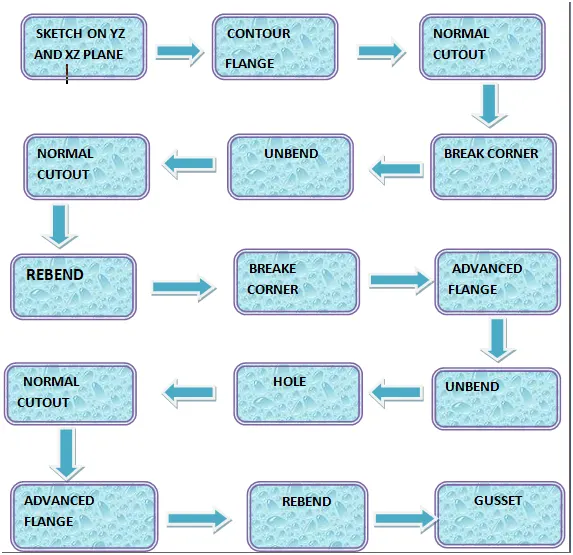
DESCRIPTION:
- SKETCH: The sketch is the fundamental base element for any feature in the design of any sheet metal Most of the features require a sketch. The very first step is to sketch which is then used to create a tab or the base feature. So, the first sketch can be called a base sketch. For other features which are the children features of the tab, the sketch may require again on plane or face.
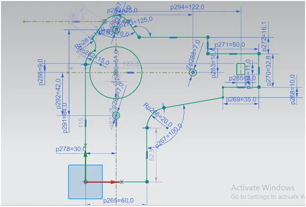
- CONTOUR FLANGE: The contour flange is a flange created using the open sketch created in a It is different from regular flange because it can be created shape and it does not require choosing the edge of any tab or existing flange. It can any position or at any angle. For this bracket design, contour flange is created using the earlier sketch as the Curve.
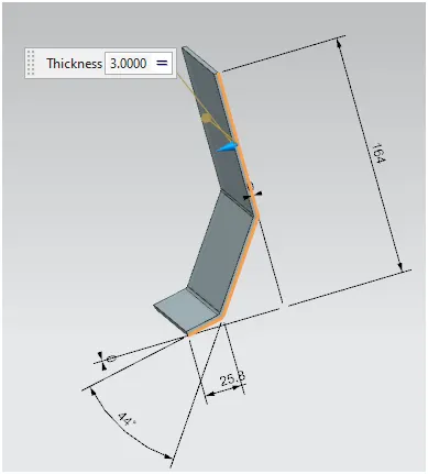
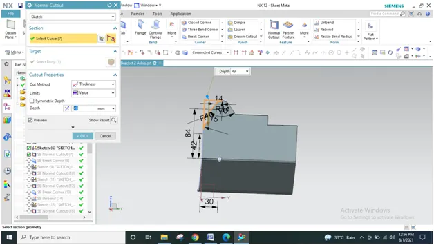
- NORMAL CUTOUT: A sketch is created on the XY plane to cut away the unnecessary material. Then the operation normal cut out is carried out. It cuts away the material at the right angle with respect to the sketch.
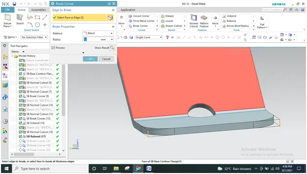
- BREAKE CORNER: This feature breaks the sharp feature of the corner and makes it round or adds chamfer .It likes the fillet feature other cad software like solid works. It prevents the feature and breaks the sharp corners.
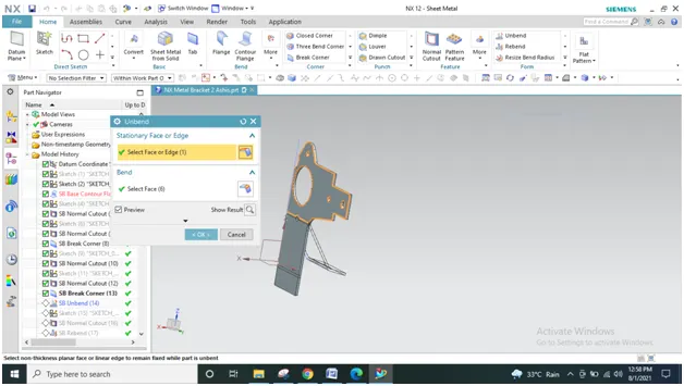
- UNBEND: This is a very powerful and very useful tool in Siemens NX. It allows all the bends made by the various features to the unbent state at once. In order to achieve a flat configuration of the sheet metal as per the design intent, it is necessary to choose the bends in order. It is also possible to box select all the bends at once. Once the unbend feature is used further features can be carried out using the sketches created in the unbent state.
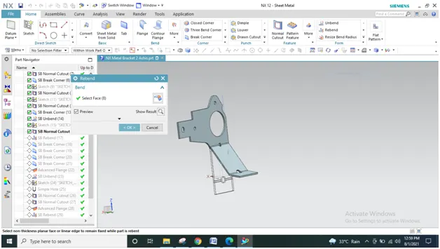
- REBEND: All the features added after the unbend feature are added in the unbend state After the addition of sketches and additional features are completed, the sheet metal component has re bend to the required position. This is done using the re bend feature and selecting all the bends in order or by box selection. This completes the design process of the casing adding the features.
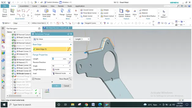
- ADVANCED FLANGE: The advanced flange can create flange from any edge which can be either curved or straight line, open or closed This allows creating a flange with a match face also. For this bracket the advanced flange is created at the upper portion with proper parameters shown.
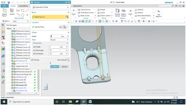
- GUSSETS: Gusset are basically supporting feature that provides of the structure of the part of the base tab or flange whenever the bend exists. These are the stiffing feature applied at the bend .For this bucket four rounded gusset are applied.
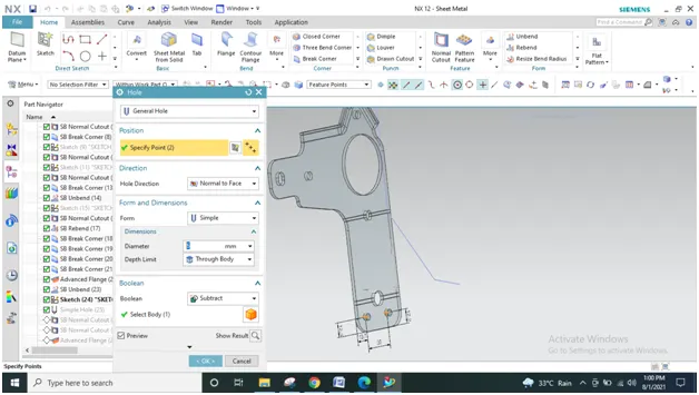
- HOLE: It can create either simple or counter bore or counter sink or tapped holes. For this bracket first the four points are sketched symmetric about x axis in position and the holes feature is applied.
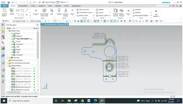
- FLAT PATTERN: Flat pattern is the representation of the entire sheet metal component in the 2D from of the with flat sheet metal with bends ,cut outs, hole ,additional; feature in the form of lines or edges .The sheet metal ensure the ability to cut the sheet metal out of the raw sheet metal plate. It removes such errors like interference or collision within the same component.
DRAWING SHEET
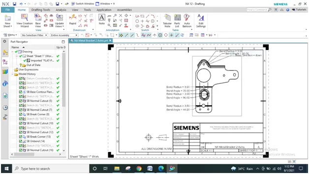
FRONT VIEW
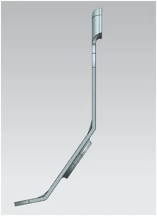
LEFT VIEW
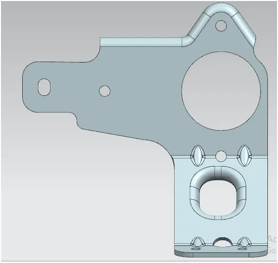
RIGHT VIEW
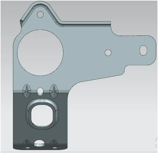
TOP VIEW
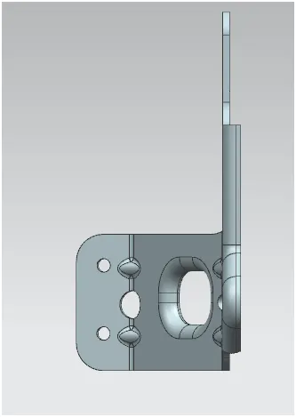
ISOMETRIC VIEW
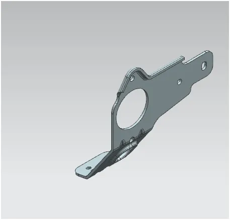
BOTTOM VIEW
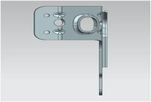
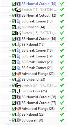
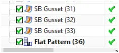
FEATURE TREE
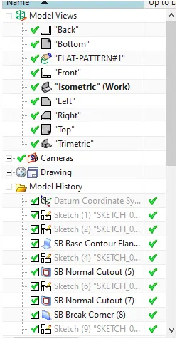
CONCLUSION:
The complex Bracket designed and the drawings were successfully displayed in this project report. The project was designed and drawing and flat pattern created using NX CAD. Thus we are able to model the part using all of feature and we learn and understand above the feature and tools of NX CAD.