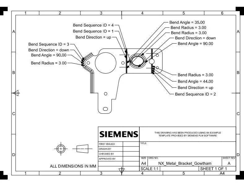
Advanced Sheet Metal Design Using NX Cad Challenge_7_ Metal bracket-II
MODELING OF METAL BRACKET II ON NX CAD
Objective :
To create 3D model of Bracket by using of NX CAD software
Introduction :
Sheet metal is metal formed by an industrial process into thin, flat pieces. Sheet metal is one of the fundamental forms used in metal working, and it can be cut and bent into a variety of shapes. Countless everyday objects are fabricated from sheet metal. Thicknesses can vary significantly; extremely thin sheets are considered foil or leaf, and pieces thicker than 6 mm (0.25 in) are considered plate steel or structural steel.
Design methodology :
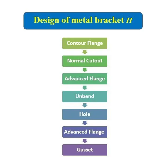
Contour Flange
Workflow :
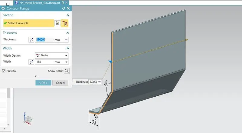
Draw 2D sketch on given dimension (Angle - 145°)
Select contour Flange optition
Give thickness and Width (T - 3mm , W - 158mm)
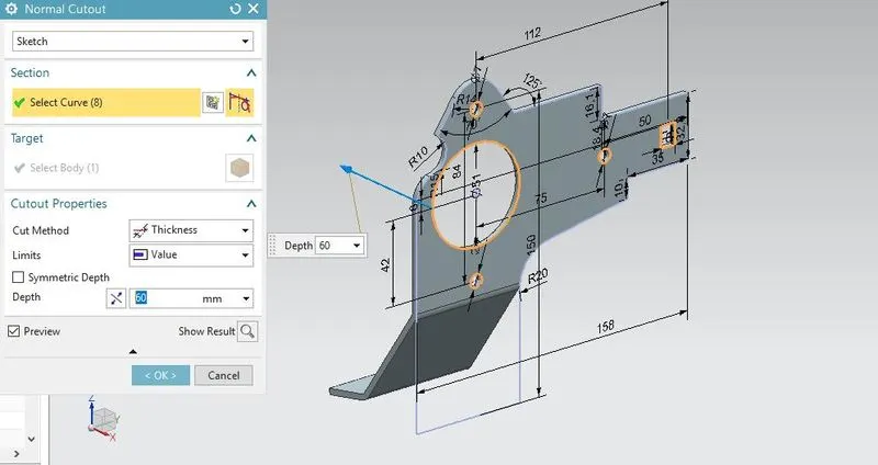
Normal Cutout
Workflow :
Draw 2D sketch on Right plane for given dimension
Select normal cutout optition
Select edge for unwanted side of face
Give depth and click ok (Depth - 60mm)
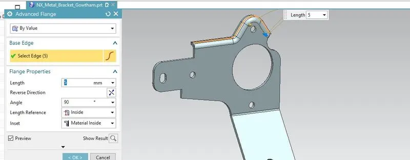
Advanced Flange
Workflow :
Select Advanced Flange optition
Select required edge to flange
Give length of flange (L - 5 mm)
Unbend
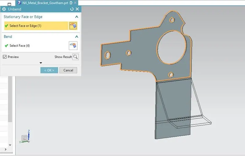
Workflow :
Open unbend optition
Select stationary face and bend face
Click ok
Hole
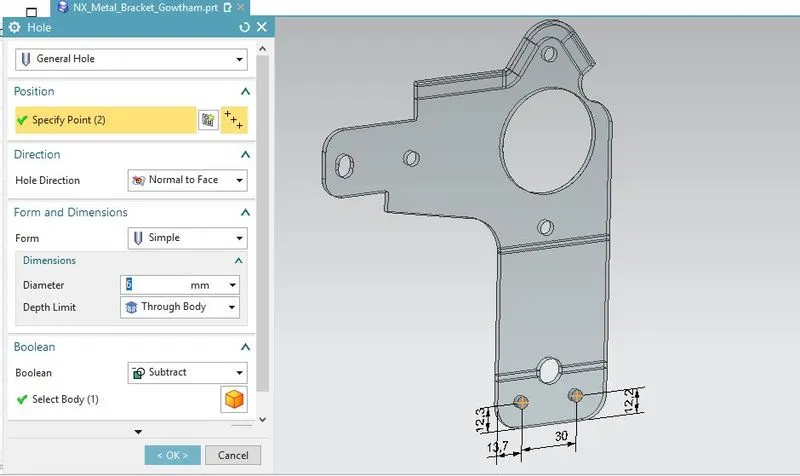
Workflow :
Draw 2D point on given dimension
Open hole optition and select two points
Give diameter (Dia - 6mm) and click ok
Advanced Flange
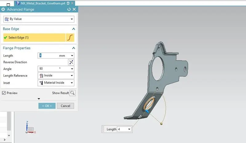
Workflow :
Select Advanced Flange optition
Select required edge to flange
Give length of flange (L - 4 mm)
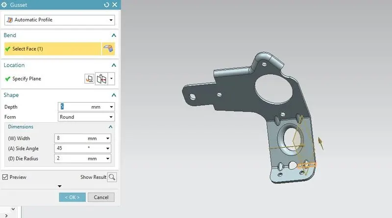
Gusset
Workflow :
Open Gusset optition
Select bend face and specfic plane
Give width , Depth , angle and Die radius (W - 8mm , D - 5mm Angle - 45° , R - 2mm)
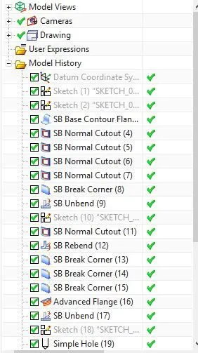
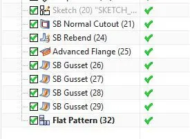
Feature Tree
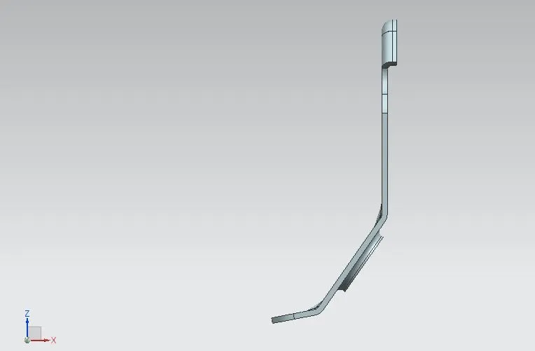
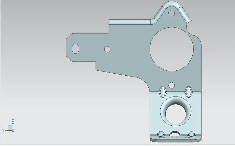
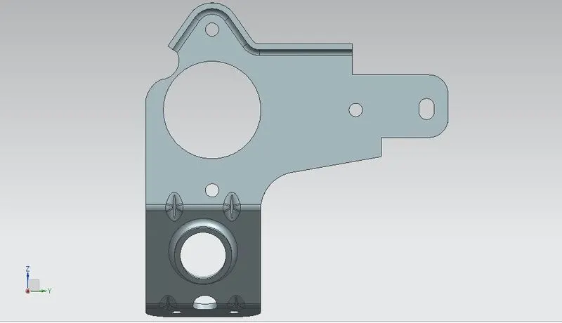
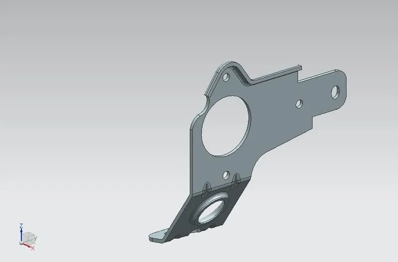
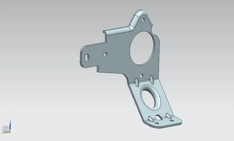
Different views of metal bracket
Drawing Sheet