Advanced Sheet Metal Design Using NX Cad Challenge_7_ Metal bracket-II
Advanced Sheet Metal Design Using NX Cad Challenge – Metal Bracket II
Objective –
- To design sheet metal bracket using Siemens NX Cad.
- To learn the various features and commands use in the creation of metal bracket.
Introduction - In NX, sheet-metal parts can be folded and unfolded enabling you to show them in the flat pattern as well as their bent-up state. There are two ways to design sheet-metal parts in NX. Either you can start the sheet-metal part from scratch using sheet-metal features throughout the design process or you can design it as a regular solid part and later convert it to a sheet-metal part. Most commonly, you design sheet-metal parts in Sheet Metal environment from the beginning.
Design Methodology –
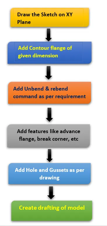
Description of command used –
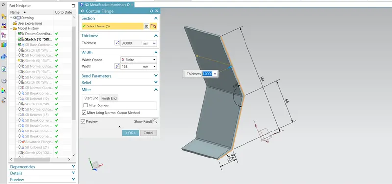
Contour Flange - The contour flange is another basic type of sheet metal feature. In order to create a contour flange, you need to have an open sketch. Activate the Contour Flange command (click Home > Bend > Contour Flange on the ribbon) and click on elements of an open sketch. Drag the arrow or type-in a value in the Width box to define the width of the contour flange.
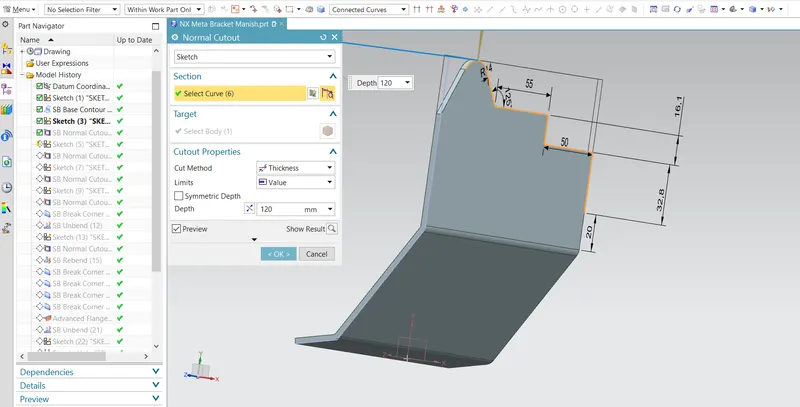
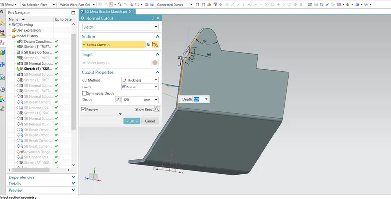
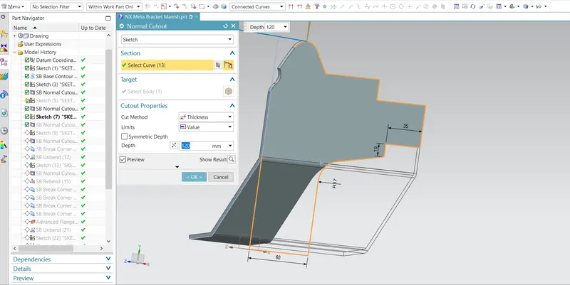
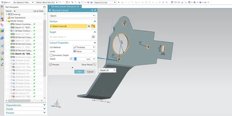
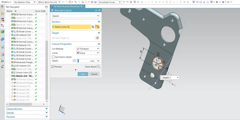
Normal Cut-out - When it is necessary to remove material from a sheet metal part, you must use the NormalCutout command. First, draw a sketch, and then activate the Normal Cut-out command. Click on the sketch and select the extent type from Cut-out Properties > Limits. Type-in a value in the Depth box in case the Limits is set to Value. On the dialog, click OK to create the cut-out.
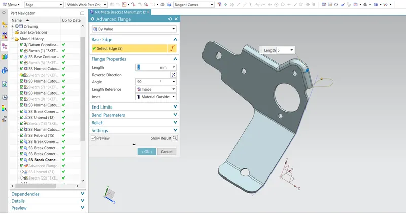
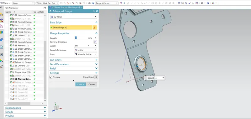
Advanced Flange - Advanced Flange adds flange along the edge using the reference face or bend angle. The edge and reference face can be curved. Flange Properties namely Length, angle, length reference and inset type are defined along with bend parameters, end limits and relief.
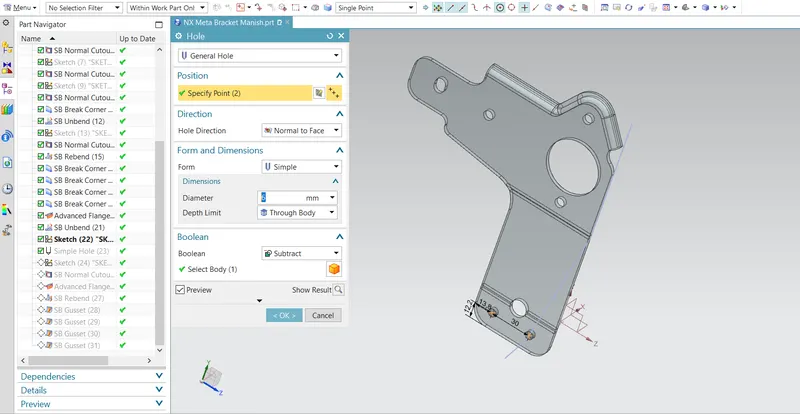
Hole – It is the feature used to create throughout circular cut out of required diameter on body.
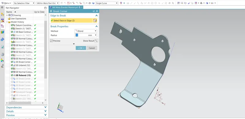
Break Corner- The Break Corner command rounds or chamfers the sharp corners of a sheet metal part.
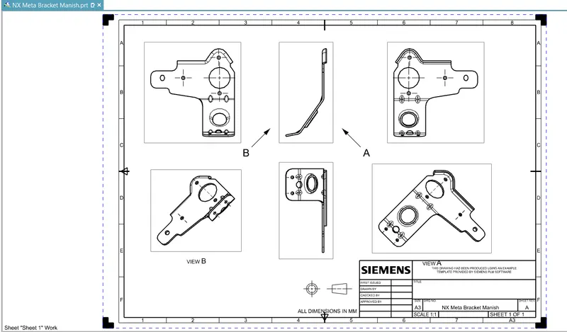
Drafting - After creating 3D model of sheet metal box assembly it can be converted in 2D drawing on sheet for the easy interpretation of model.
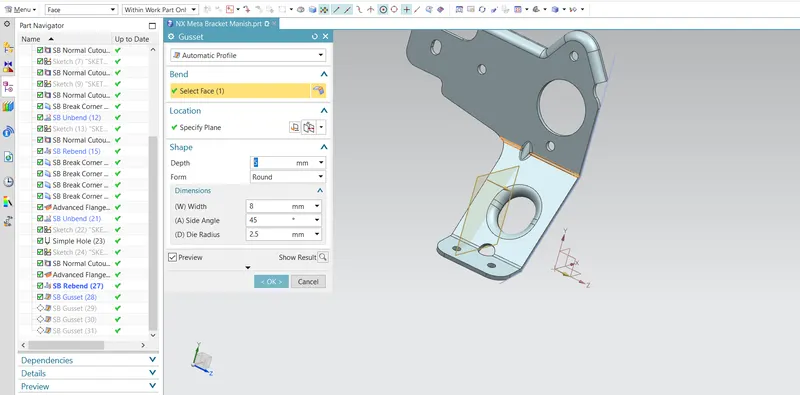
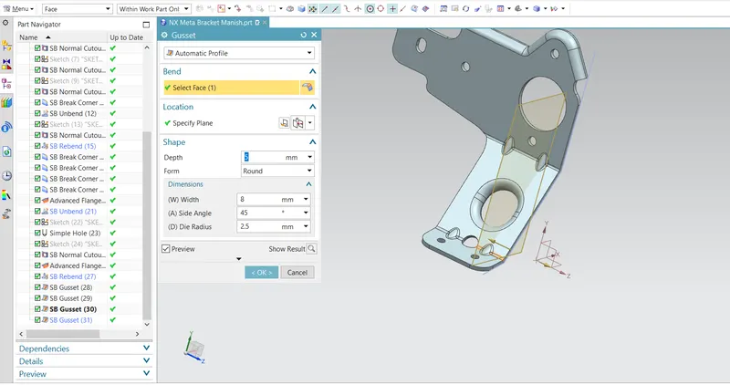
Gusset- Gussets are stiffening features created across a bend to reinforce the sheet metal part. Activate the Gusset command (click Home > Punch > Gusset on the ribbon) and click on a bend face. A gusset feature appears along with Distance box attached to it. Type-in a value in the Distance box or drag the arrow to define the location of the gusset.
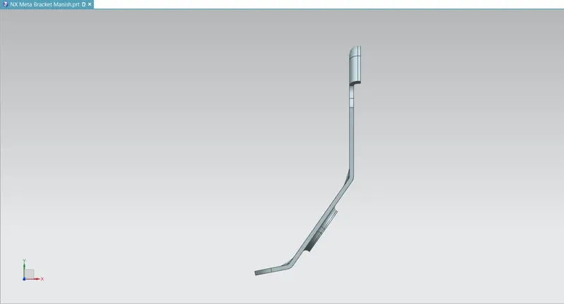
Different views of Model –
Top View
Front View
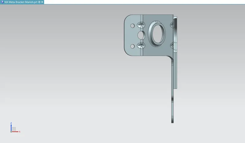
Left View
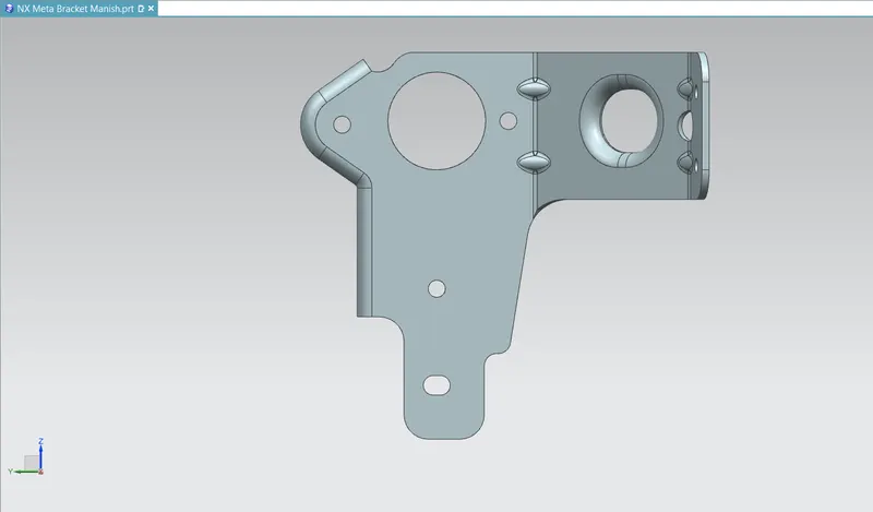
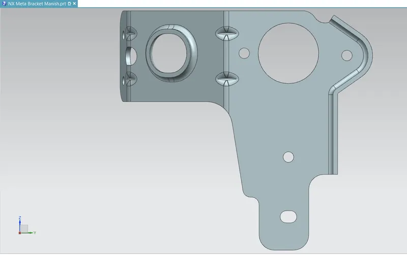
Right View
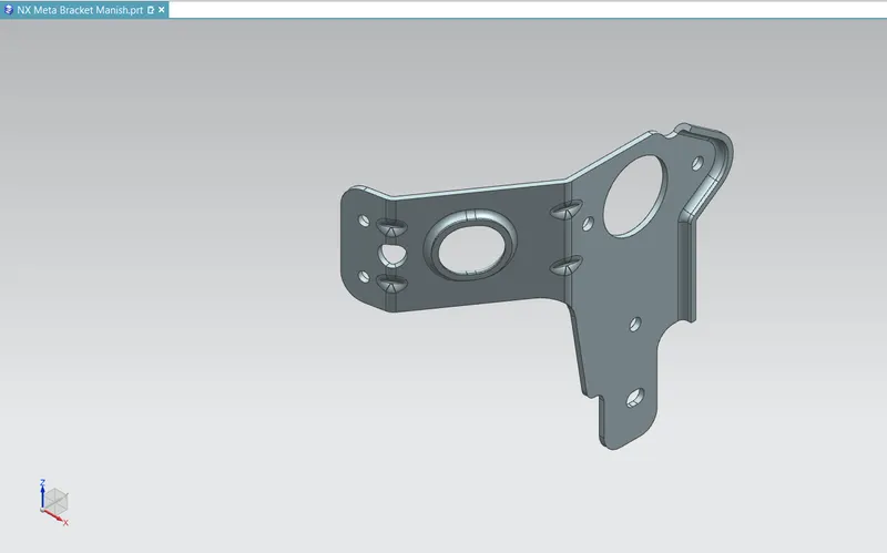
Isometric View
Conclusion –
- Design sheet metal bracket successfully by using NX cad.
- Learn features used in the creation of model.