Advanced Sheet Metal Design Using NX Cad Challenge_7_ Metal bracket-II
- Title of the Project: Bracket - II
- Objective: to provide and overview of using Advanced features in NX CAD
- Introduction : Create Bracket from the 2d Drawing using Advanced features in NX CAD
- Design methodology / approach:
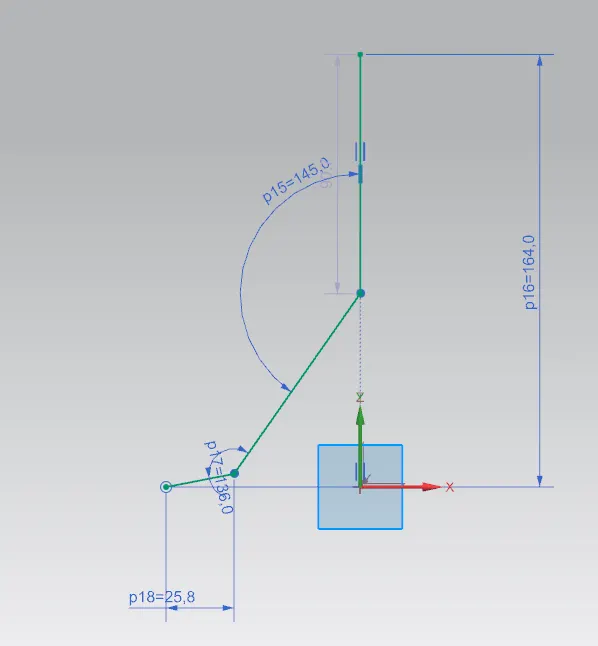
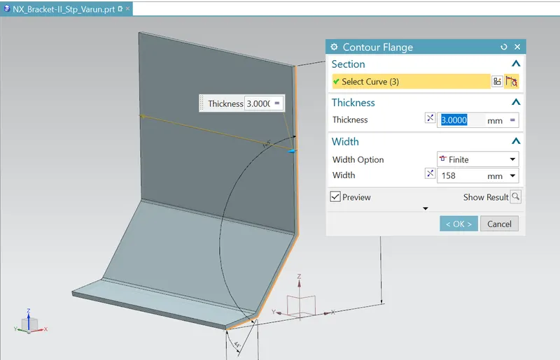
- Create a Front view using sa contour flange
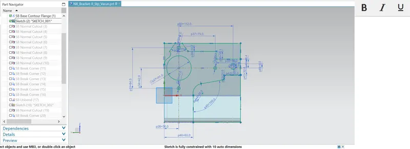
- After creating flange of the shape above use the side view faces to start sketching the curves from the 2D
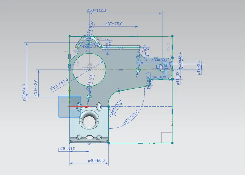
- Use normal cut feature to remove unwanted surface as shown
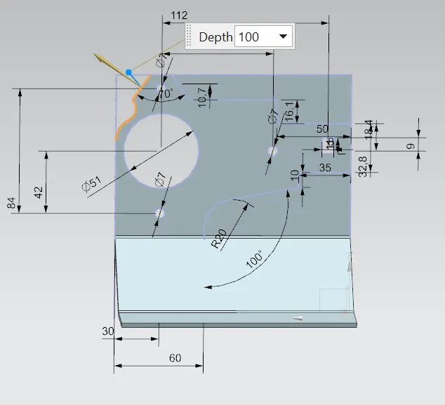
- make the holes and using normal cutout feature
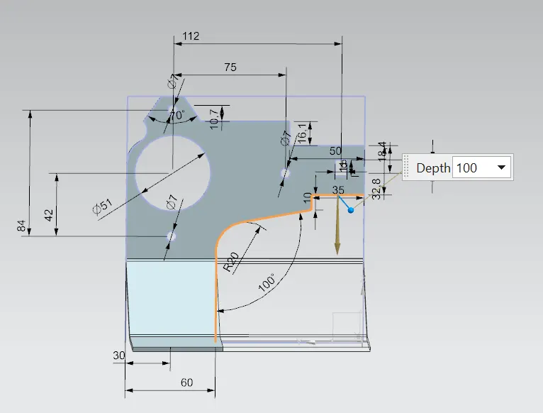
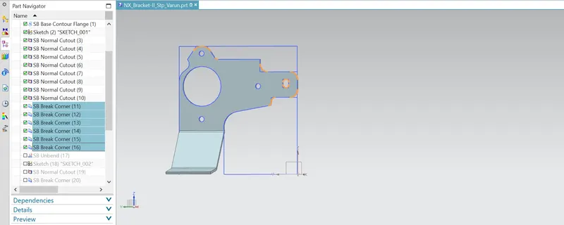
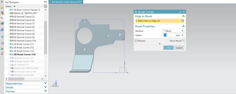
- Use Break corners feature to create fillets inside a square hole cutouts
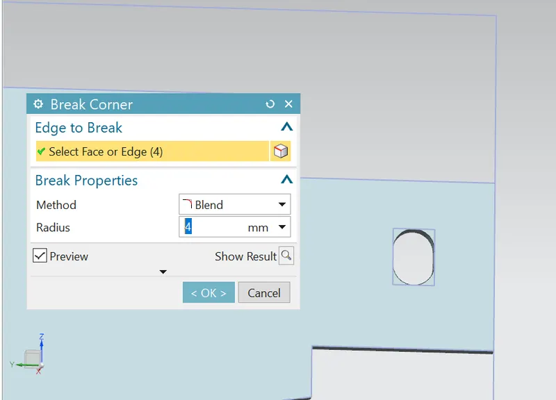
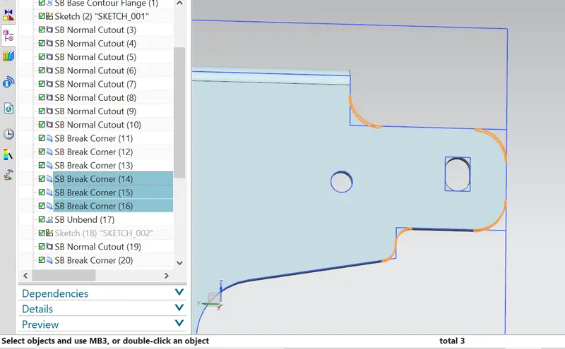
- Use Break corners to create fillets at the sheet metal corners
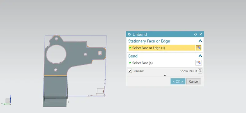
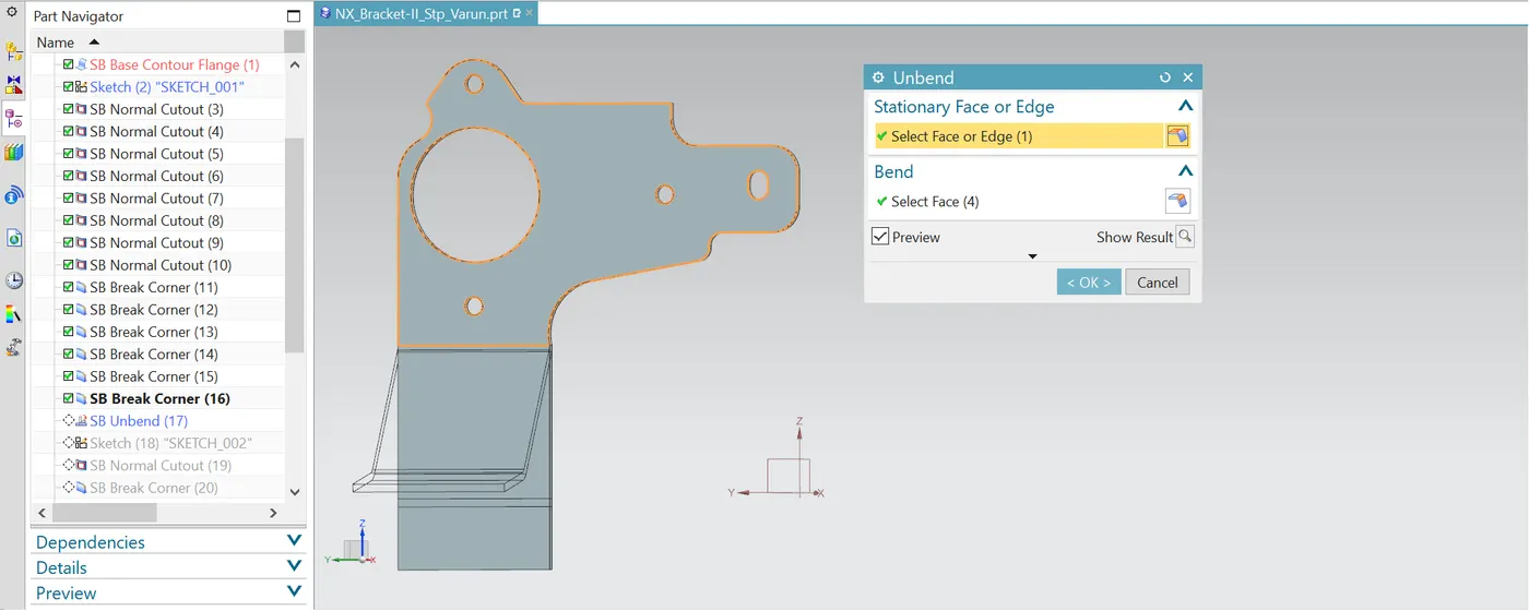
- Unbend the sheet metal
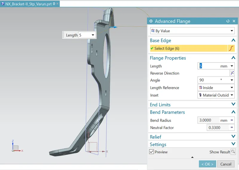
- Create advanced flange at the top corner
- Create Gussets as shown below at four corners
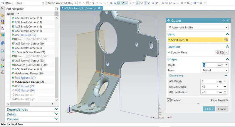
- Create a Front view using sa contour flange
- Description (Need to explain tools/ Features used while designing):
- Firstly used Contour flane tool to create the basic blank
- Next used the side views to create sketches to remove the unwanted sheet metals to create the required shape
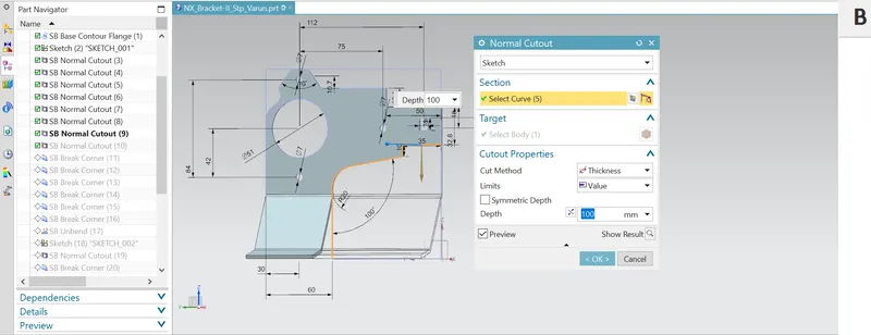
- Further used Breaker corners to create Fillets at the corners of the edges and also the at the square hile to create the required eliptical shape
- Used unbend option to unbend the sheet metal to create required hole
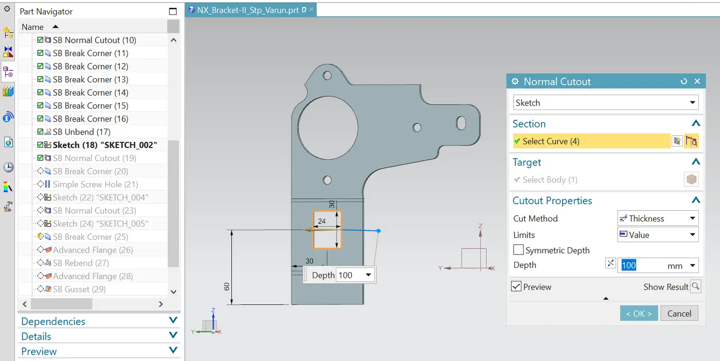
- Executed normal cutotu feature at the bottom and used breaker corner feature to create required fillets innerside of the cutout as shown
- General Hole of 6mm diameter are created as shown
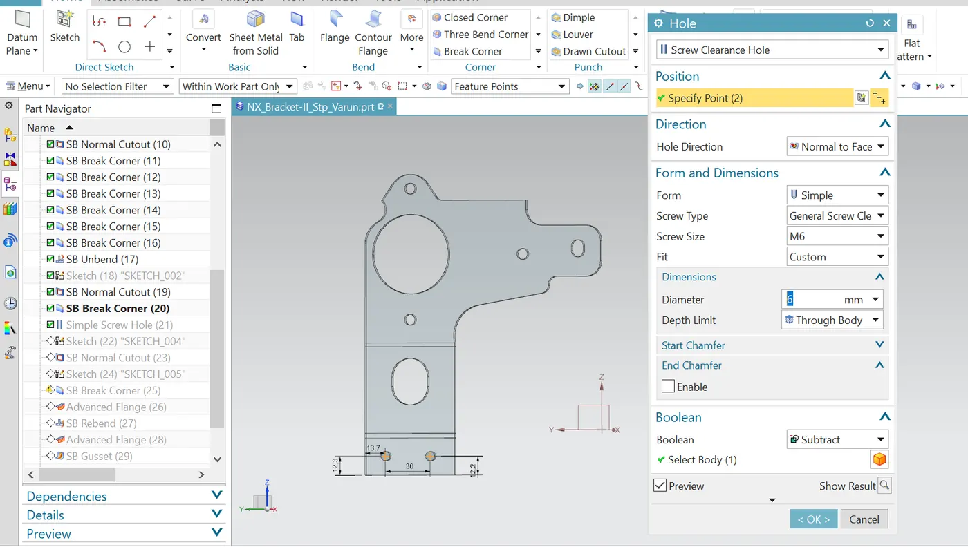
- Used advanced Flange feature to create the flange for the curved shapes
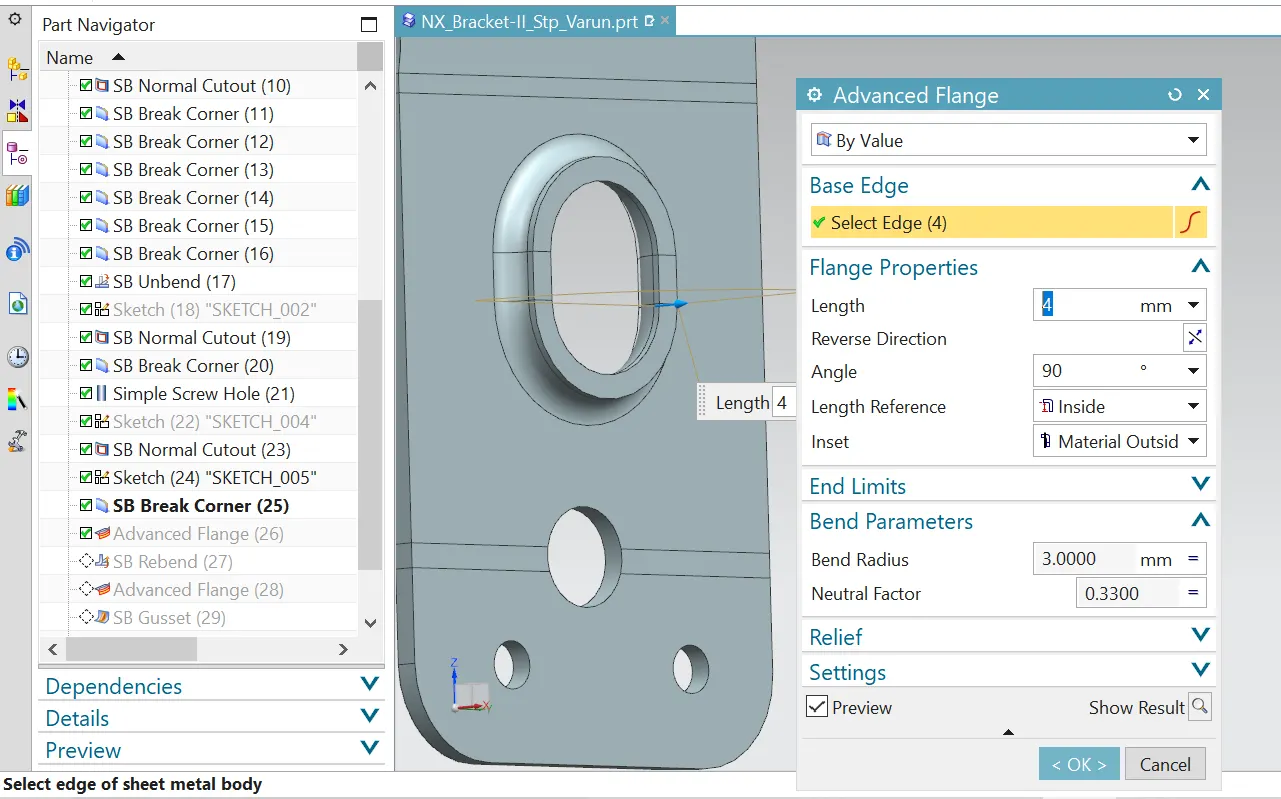
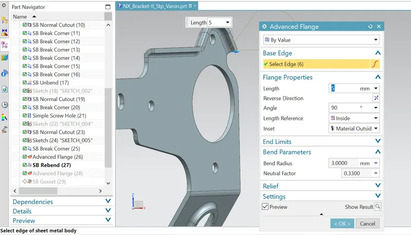
- At last used gusset features to create gussets at the 4 locations near bend corners
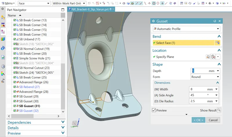
- Firstly used Contour flane tool to create the basic blank
- Upload a min of four screenshots of Model in the report.
- Front View
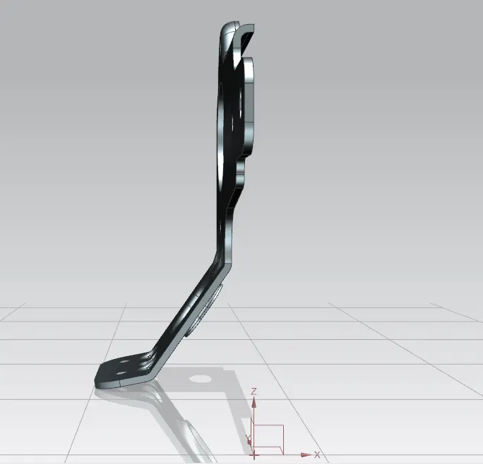
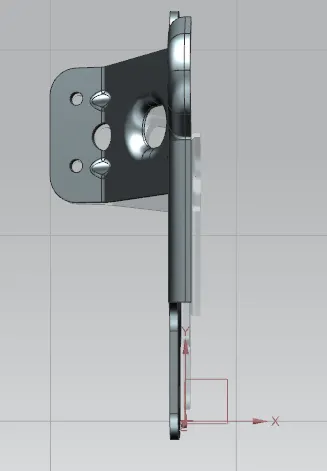
- Side View ->Left side:
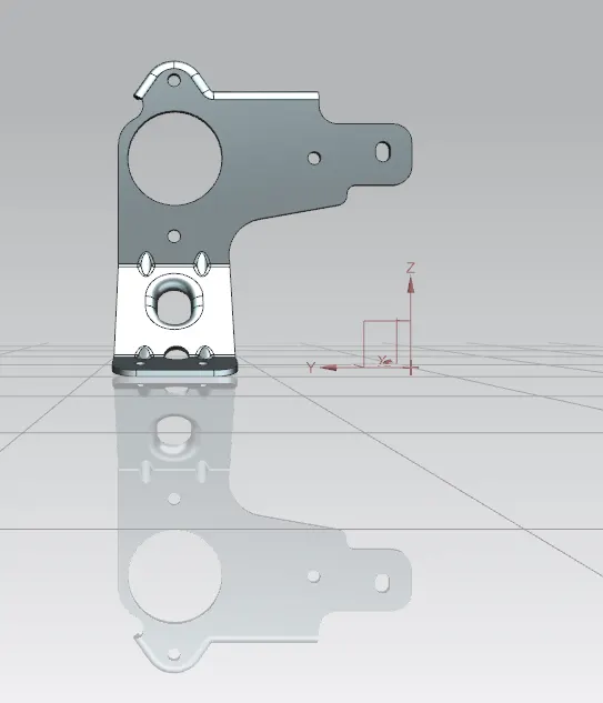 Right side: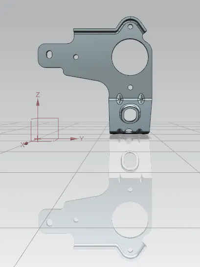
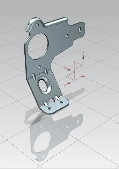
- Isometric View:
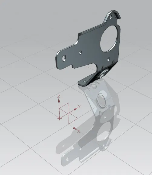
- Top View:
- Front View
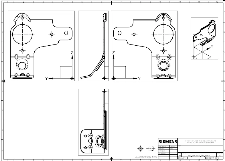
- Attach Detailed Drawing Sheet Image:
- Conclusion: The part is created and saved as Step file in the above mentioned name.