Advanced Sheet Metal Design Using NX Cad Challenge_2_Box Assembly
- Title of the Project: NX_Box_Assembly_Varun
- Objective: To explain every step involved in creating the Box assembly.
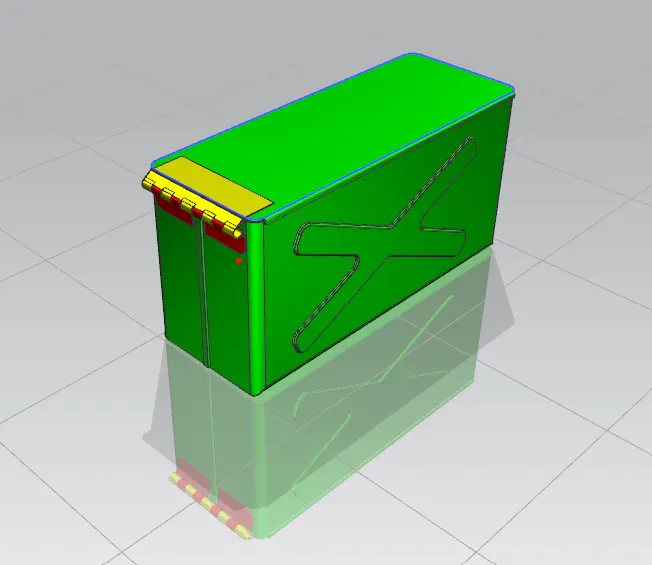
- Introduction: In this project we are creating a Box Assembly as in the pictures.
4. Design methodology / approach (To be explained with the help of Flowcharts only):
- Open NX CAD --> open a new model from the selection
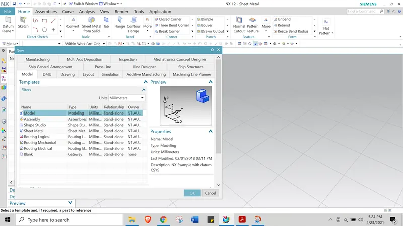
- Select --> Model from the menu
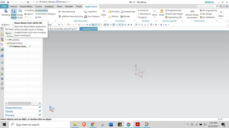
- From Application --> Sheet metal
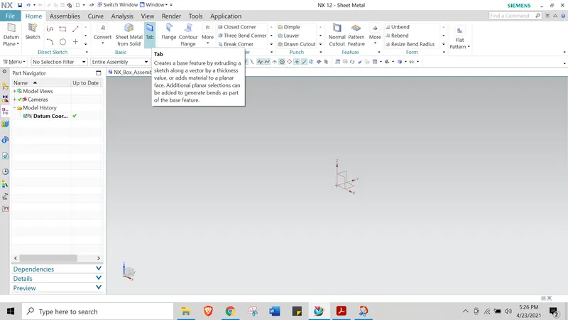
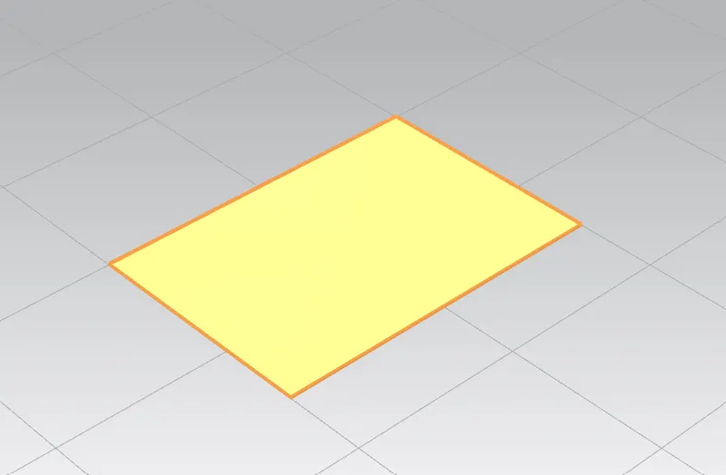
4. Select --> Tab to create a Tab with L=200 and B=150
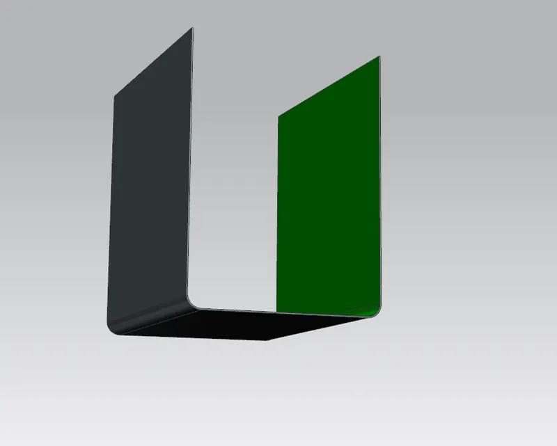
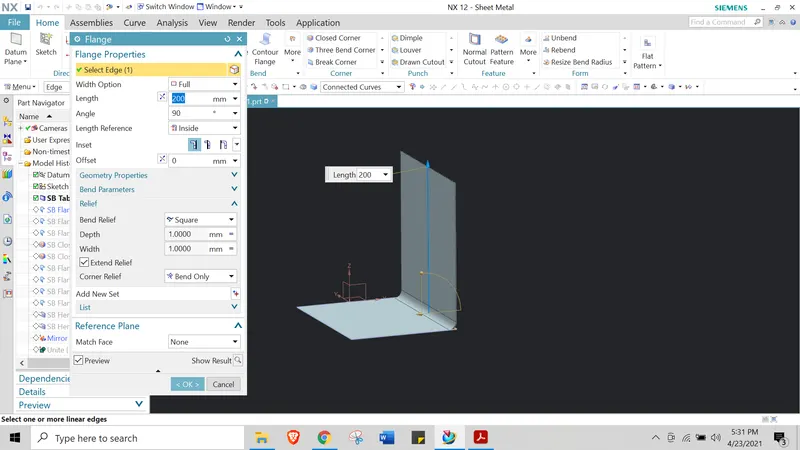
5. Add Flange on both the side of length --> L= 200mm; Material Outside and Radius 10mm
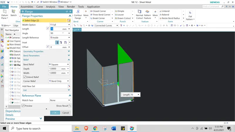
6. Add Flanges --> on the Horizontal sides of the previous flanges as shown.
7. Add --> Close corners to the new flanges to cover the gap between the base and the flange.
8. Create two opposite Flanges --> with the Radius 0.02 mm and angle 0 as shwon below.
Left side:
Right side:

9. Add Flange --> L= 6.5; angle 90; L reference = Outisde on both the sides
Right:
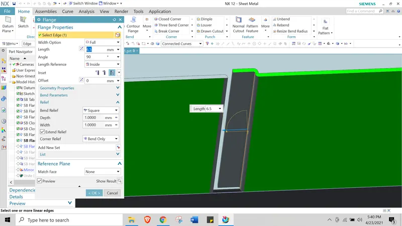
Left:
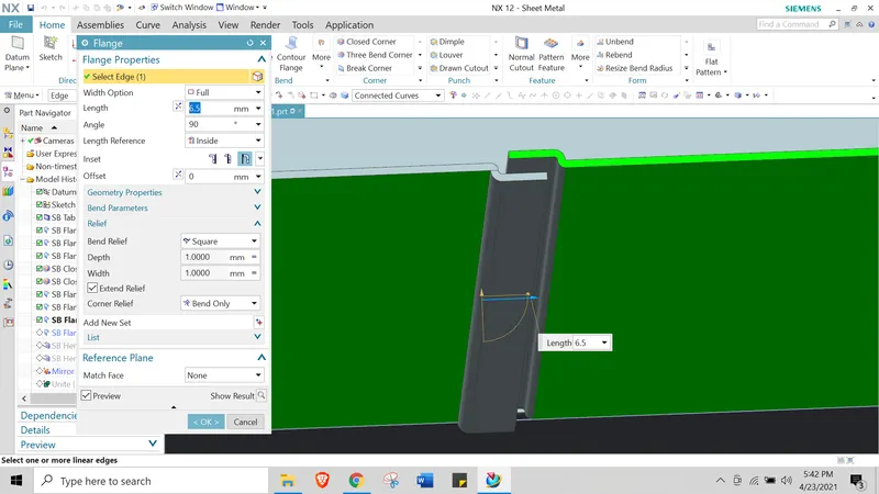
10. Create Hem Flange --> Type=open; Radius=0.5mm; Length=5mm on both side
Right:
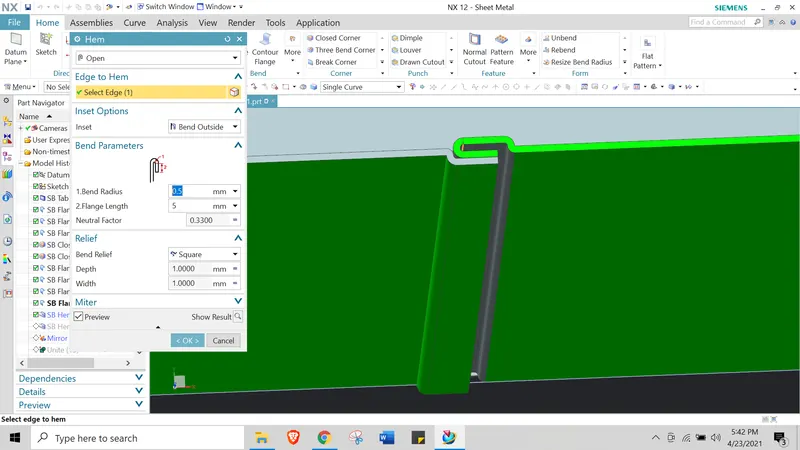
Left:
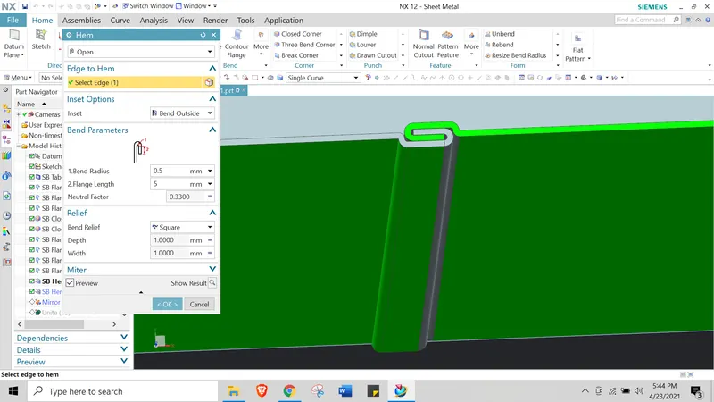
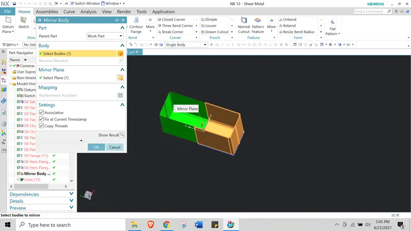
11. Mirror--> Mirror bodies using the existing datum plane as reference.make sure to select associative, fix at current timestamp, copy threads.
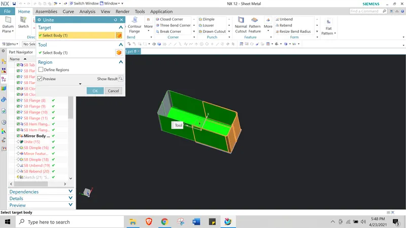
12. Unite --> Use the Unite option to combine the mirror body with the original first body.
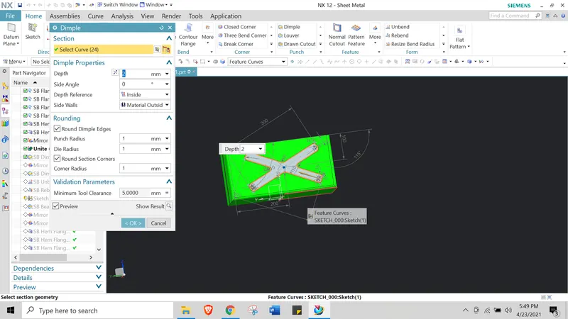
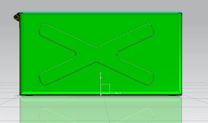
13. Dimple--> Create a dimple of the side surface as shown below.
14. Mirror--> use mirror option to mirror the dimple on to the opposite face.
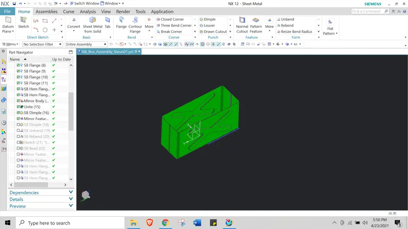
15. Create --> Rectangular dimple at the bottom surface as shown below.
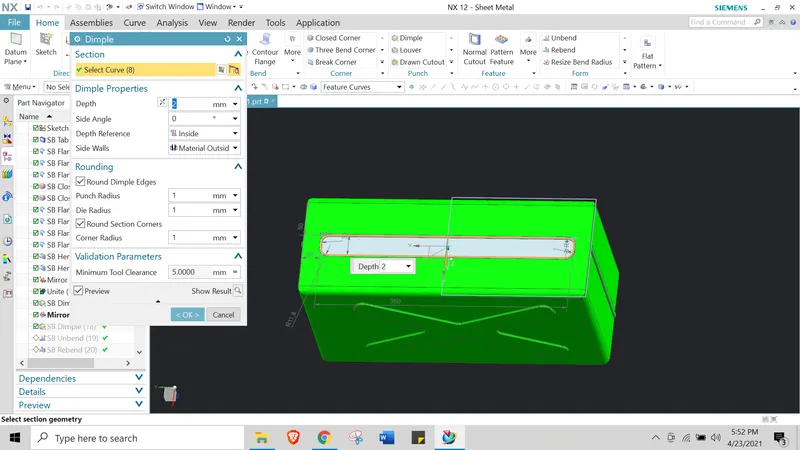
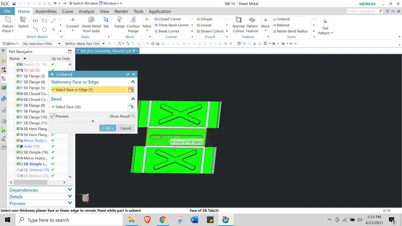
16.Unbend --> use unbend option by fixing the base part as fixed surface and unbend all the features.
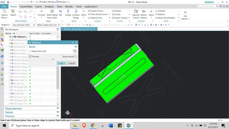
15. Rebend --> use rebend and select all the features by draging the cursor.
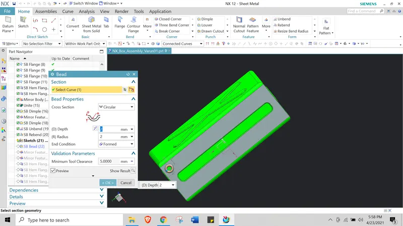
16. Bead --> Create a Circular bead using a circlar sketch with R=10 L=20mm from top and side edges.and use mirror option to create 4 beads at four corners.
17. Hem flanges --> Create closed Hem flanges at all the top edges as shown.
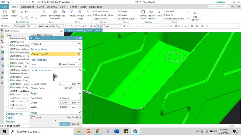
18. Datum--> create a datum plane at L=203mm as shown
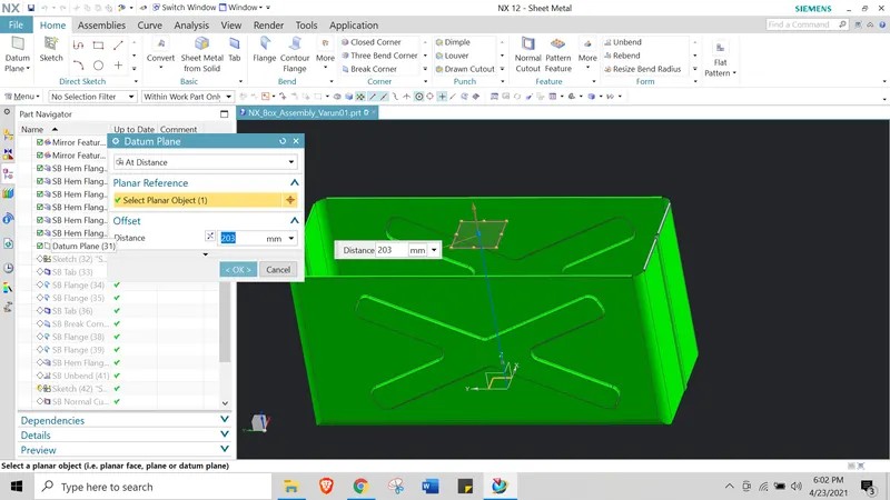
19. Tab --> Create a tab for lid cover covering all the top surface.
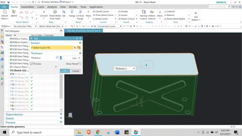
20. Flanges --> Create flanges to cover the side surfaces
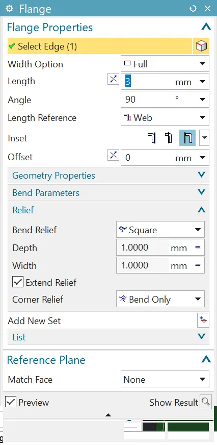
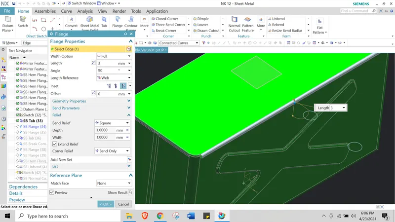
21. Tab --> Create a tab on front surface.
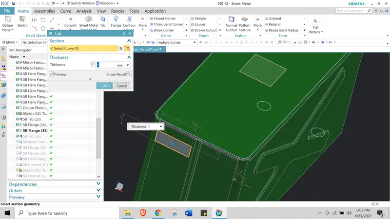
22. Beak corner --> Break corner with R=10mm
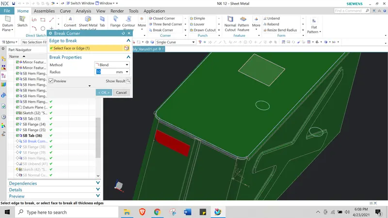
23. Flange --> add 40deg flange of 4mm and add 2nd flange of 40deg of 4mm
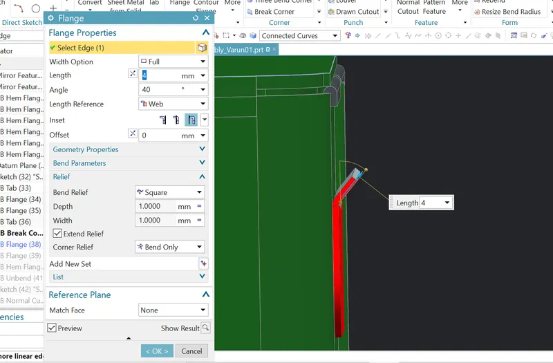
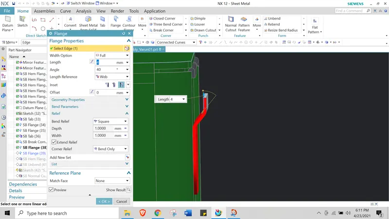
24. Hem flange --> Create a open loop Hem with the R =5mm and angle 325 deg
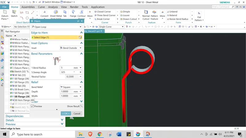
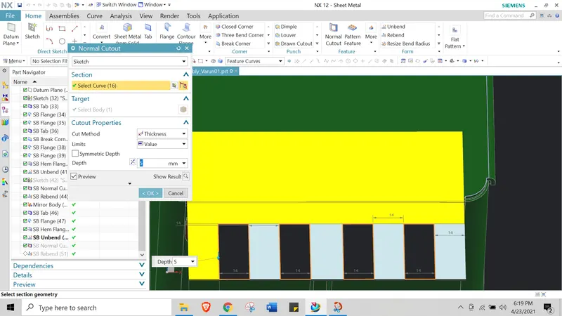
25. Unbend and normal cut --> unbend on the hem flange and normal cut the following dimensions.
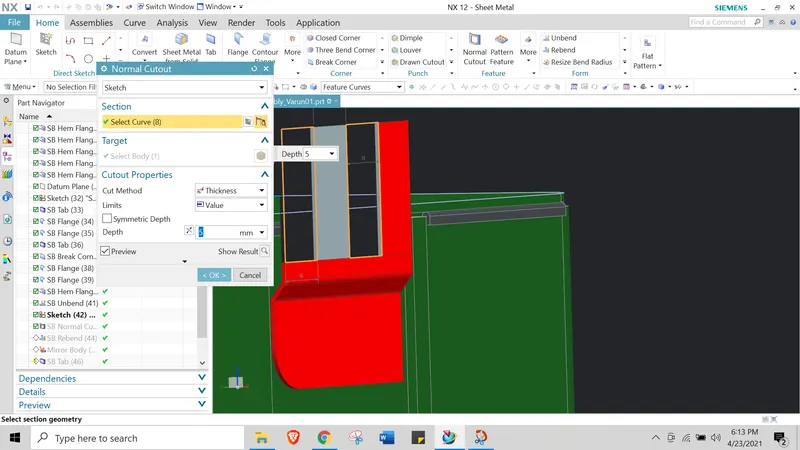
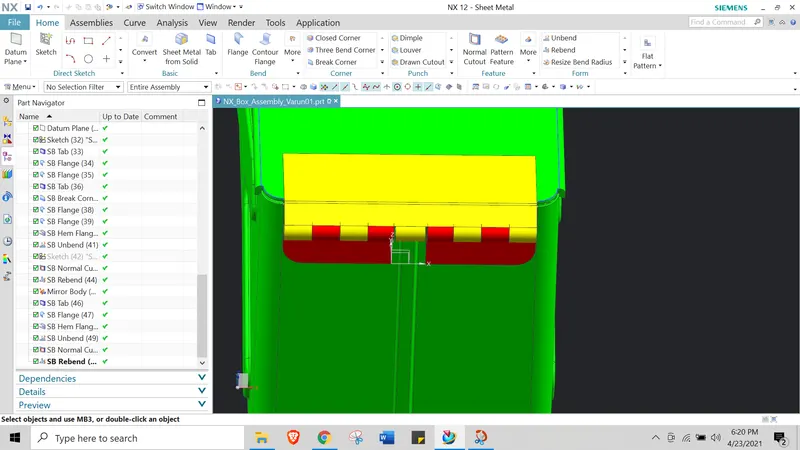
26. Rebend --> use rebend to convert back to hem flange
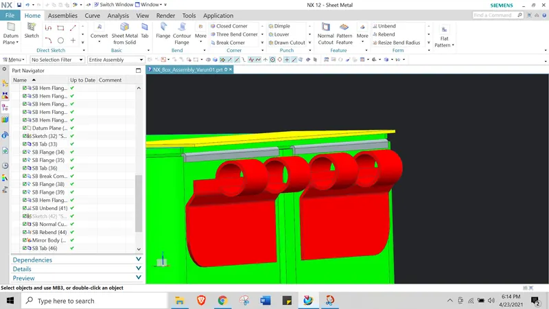
27. Mirror features--> use mirror to create mirror of the hem flange sturcture
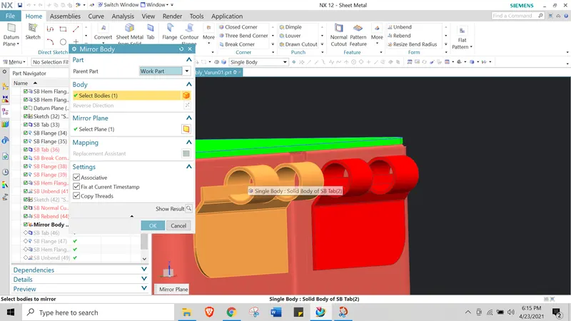
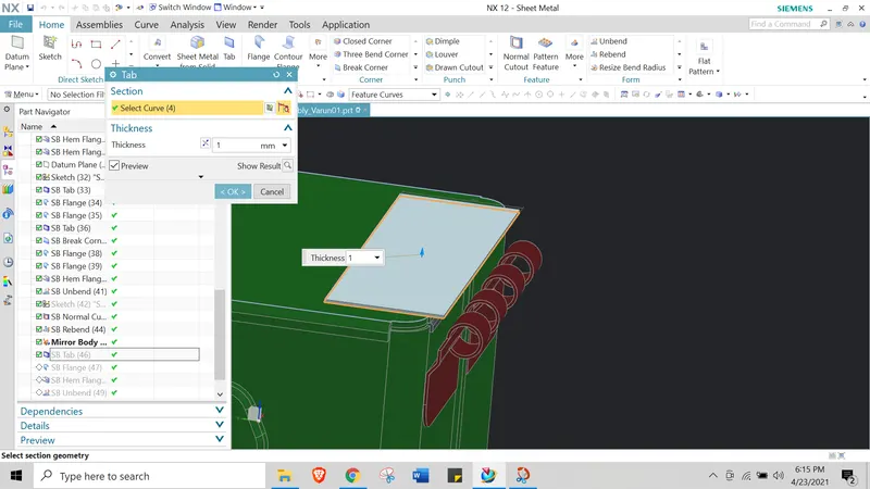
28. Tab --> Create a tab for lid clamp
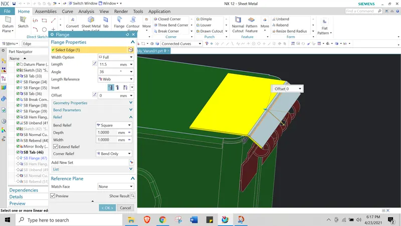
29. Flange --> Create a flange of L=11.5 and angle 36 deg
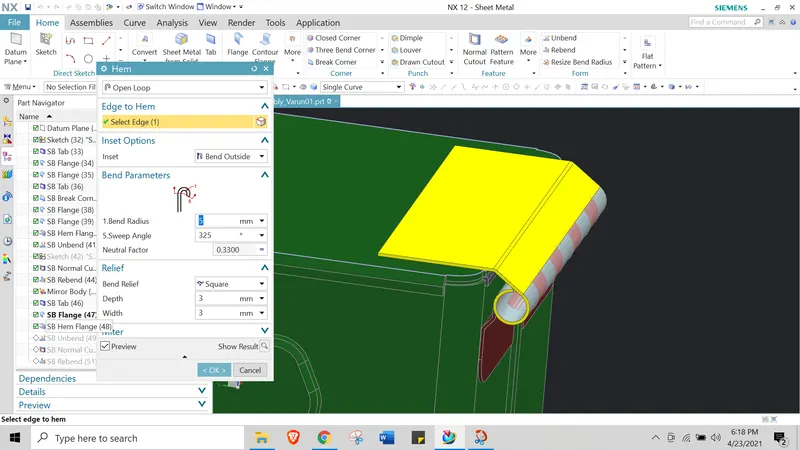
20. Hem flange --> create a OPEN LOOP hem flange of R-5mm and Angle=325.
31. Unbend and normal cut out --> Unbend and use normal cutout with the given dimesnions
32. Rebend --> use rebend option to bring the hem flange.
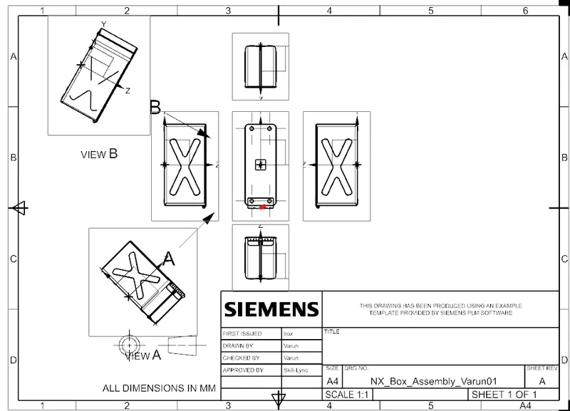
Drafting:
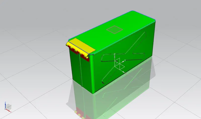
Isometric View:
Top View:
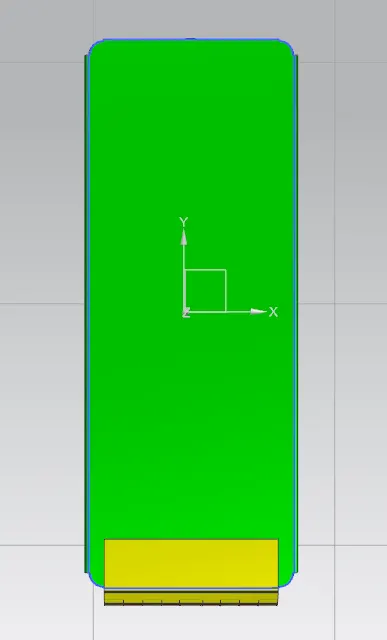
Front view:
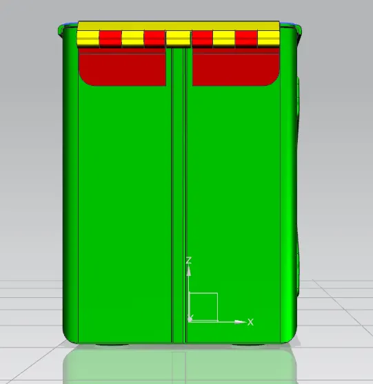
Bottom View:
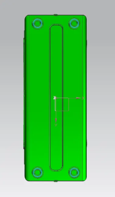
Right Side views:
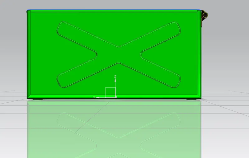
Left side View:
CONCLUSION: The Box assembly is created and the file is attahced for review.