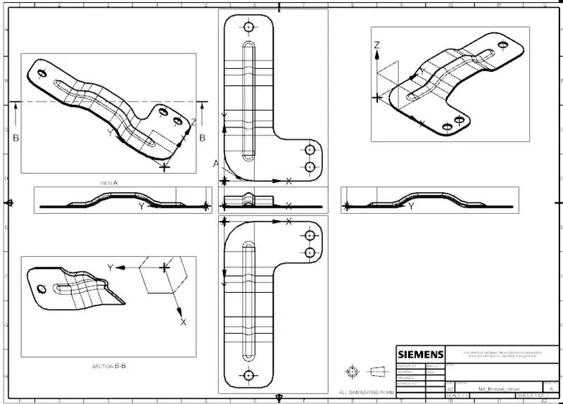
Advanced Sheet Metal Design Using NX Cad Challenge_6_Bracket
- Title of the Project: NX_Bracket
- Objective: To provide and overview of using Advanced features in NX CAD
- Introduction : Create Bracket from the 2d Drawing using Advanced features in NX CAD
- Design methodology / approach: Below flow chart
- Create a contour flange
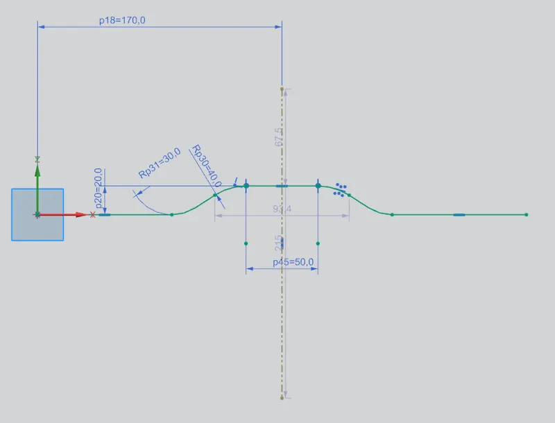
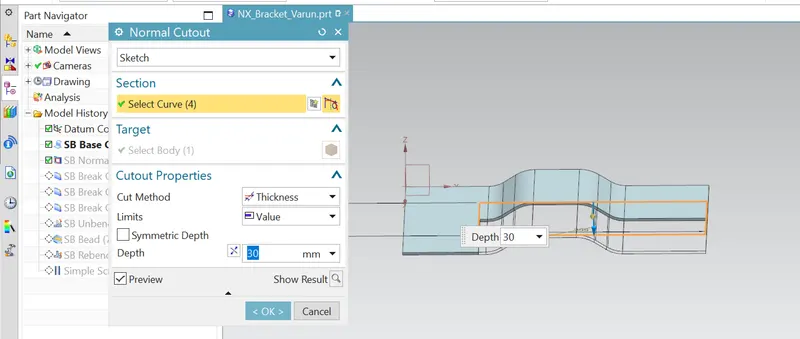
- Sketch the cutout region on the front face as shown
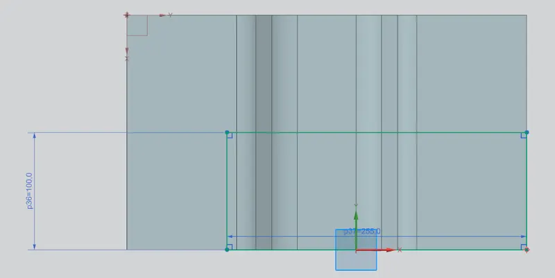 and used normal cutout tool to remove unwanted surface.
 - Use bendcorner to create chamfer
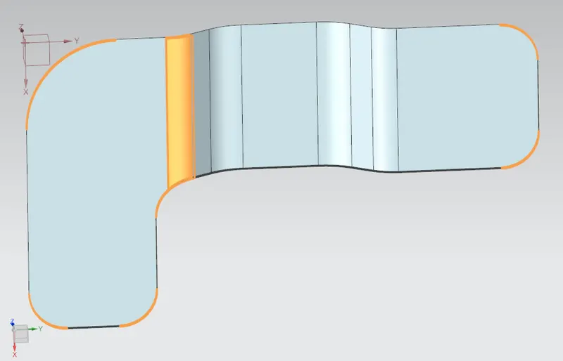
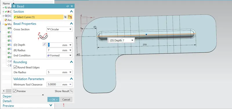
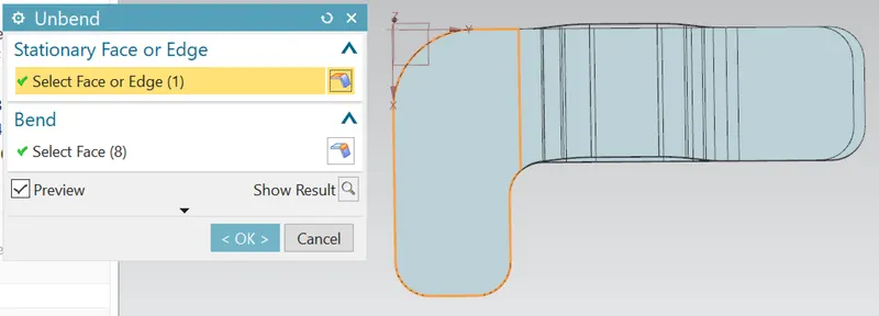
- Use unbend option to flaten and create bead as shown.
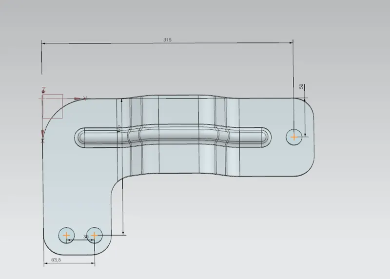
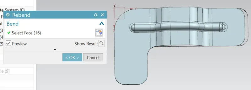
- Rebend the sheet metal and use General hole option to create holes at required locations mentioned
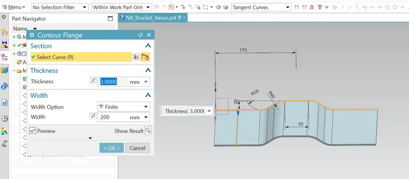
- Create a contour flange
- Description:
- Open new Sheet metal module and use Contour flange to create the sketch as shown. and add thxikness of 3mm and width of 200mm
- Now use Normal cutout option and cut out unwanted material for depth of 30mm as shown
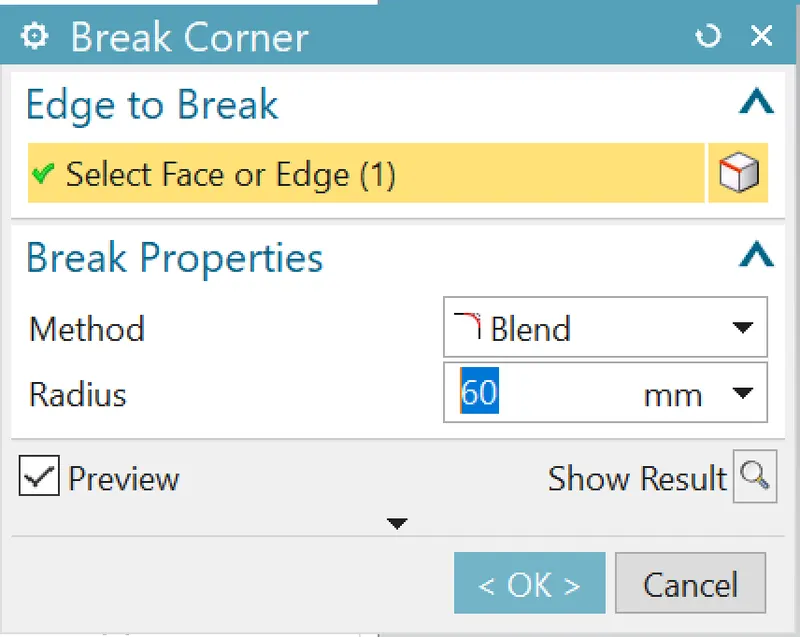
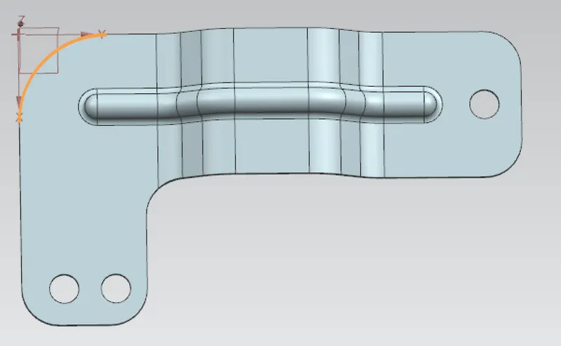
- Create Break corner at one location with radius of 60mm
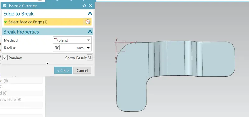
- Create Break corner at one location of radius 30mm
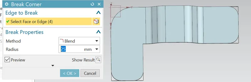
- Create another beak corner at 4 locations of radius 25mm
- Use Unbend shape option
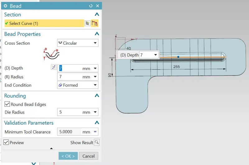
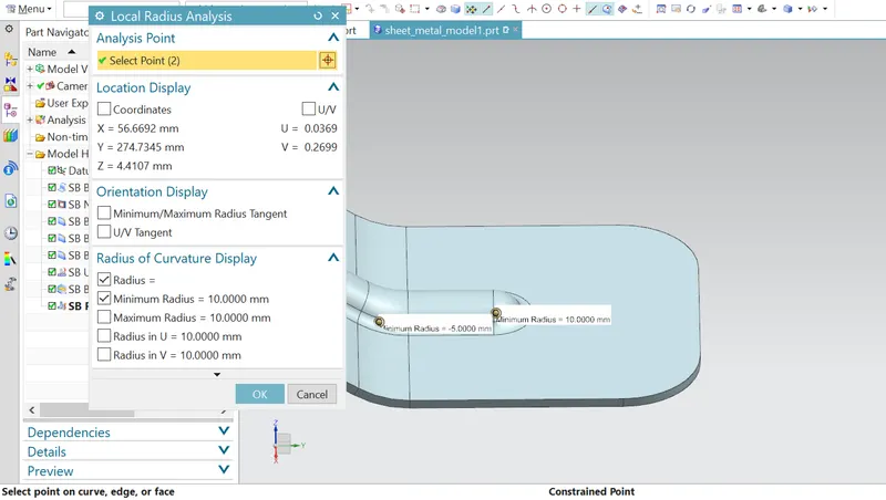
- Use bead option to create bead at the location mentioned
- Rebend the sheet metal and use general hole option to create 3 holes
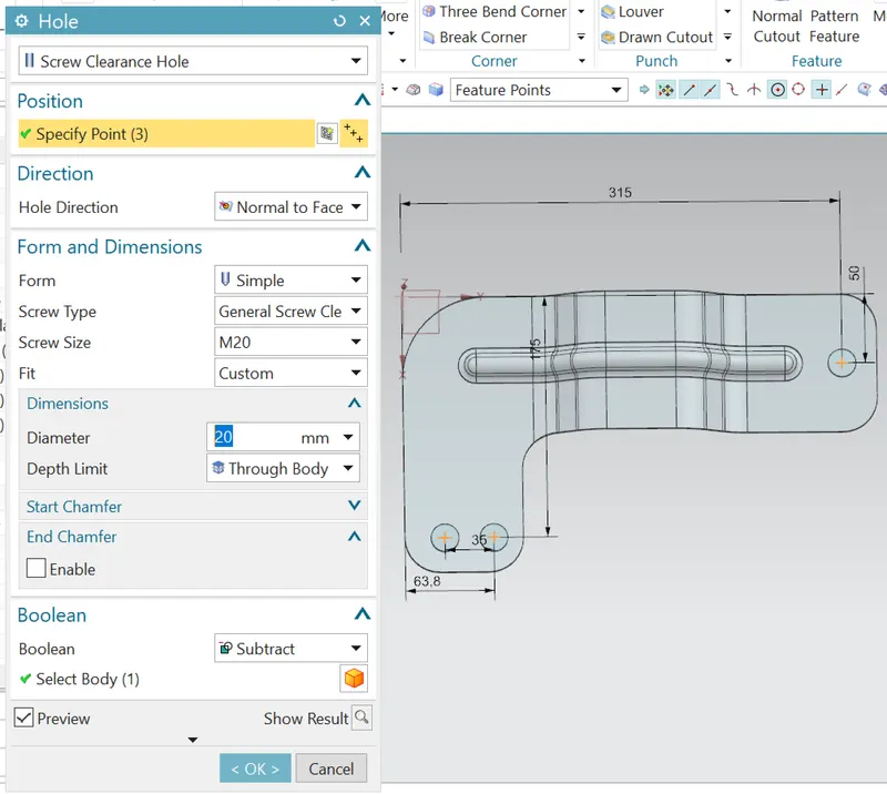
- Open new Sheet metal module and use Contour flange to create the sketch as shown.
- Views:
- Isomteric View:
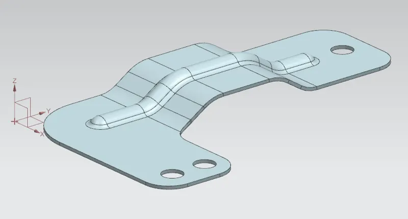
- Front view:

- Top View:
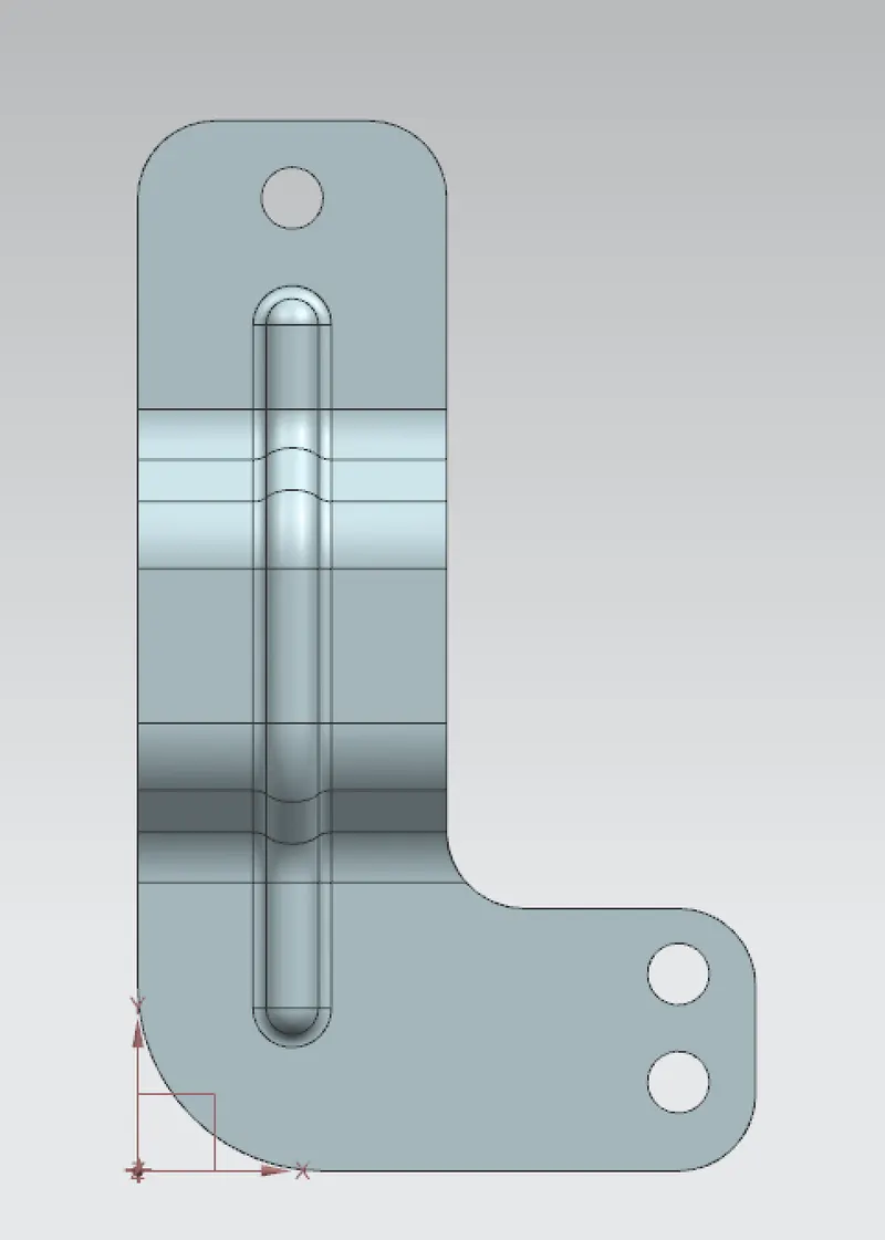
- Bottom View:
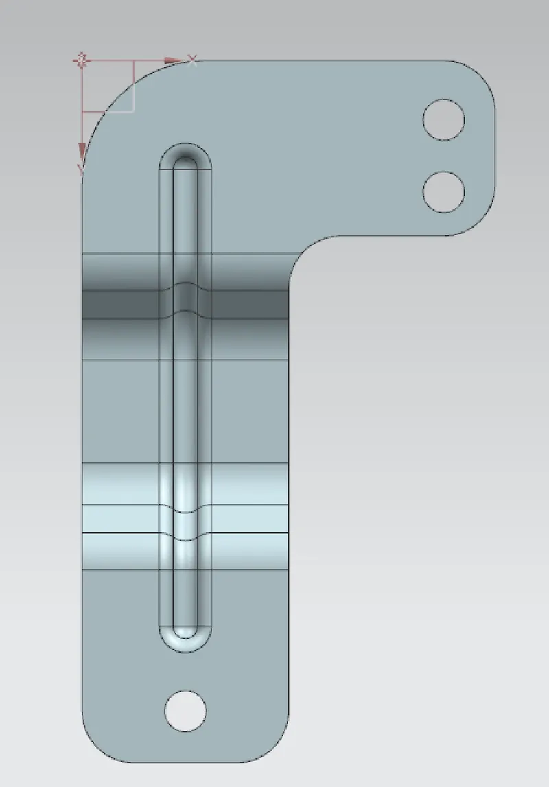
- Right side view:

- Left side view:

- Isomteric View:
- Detailed drawing and drafting:
- Conslusion:
- The sheet metal part is created as requested in the 2d drawings provided.