Advanced Sheet Metal Design Using NX Cad Challenge_1_Casing Design
- Title of the Project: NX_Casing_Varun
- Objective: To Illustrate step by step process in creating a sheet metal part using the features in the tool.
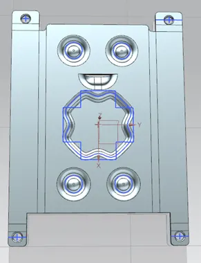
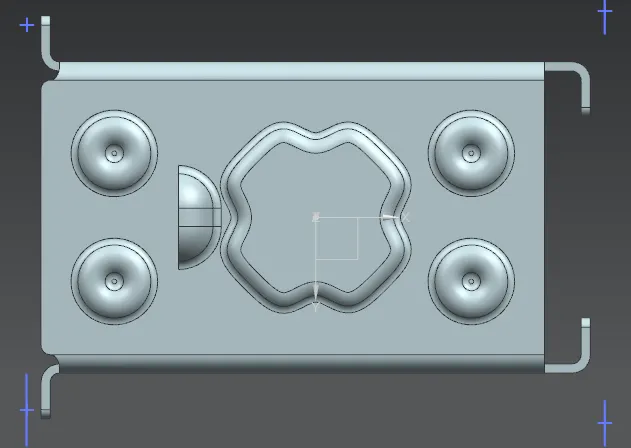
- Introduction: NX CAD Sheet metal designing tool is used to create sheet metal parts. This project is to create a casing as shown in the figure.
- Design methodology / approach (To be explained with the help of Flowcharts only):
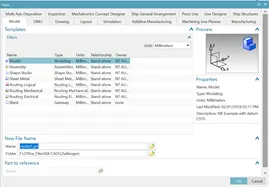
- Open NX CAD --> open a new model from the selection
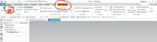
- Go to Application from the top menu bar --> select Sheet metal module
- Go to Home from the top menu --> model sketching

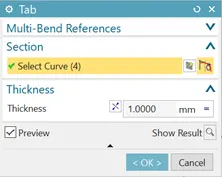
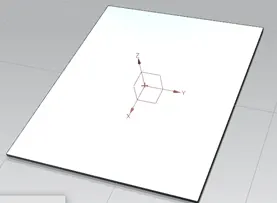
- In Home --> Select Tab to create a tab from the basic section dimension 60mm in X -axis direction and 50mm in Y-axis direction and add thickness of 1mm
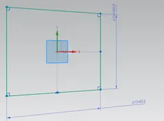
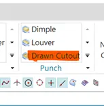
- In Punch --> select Drawn cutout and use the sketch option to create rectangle of dimension 5mm X 30mm
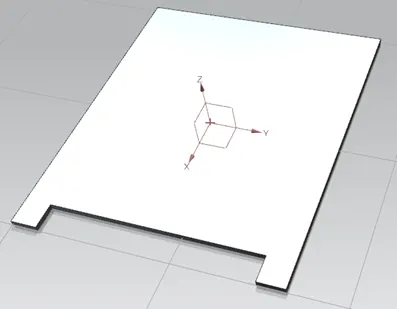
- Open Sketch --> draw a symetric lines parallel to Y-axis (10mm from edges)à to use bend option from form option
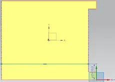
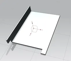
- Similarly create a bend option --> form options
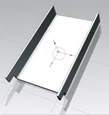
- From Bend option --> Create Flange or Web 5mm on four corners. The top at the cut out should be inwards and the other to be outwards
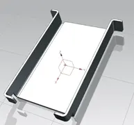
- From Corner --> select Break Corners to chamfer or smoothen the sharp edges
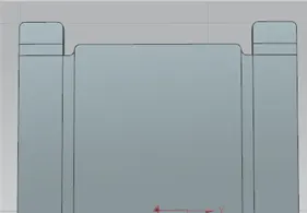
- In Form -->Select Unbend option. In unbend 1st -->select Base as the center plate, 2nd -->select all the other features to unbend
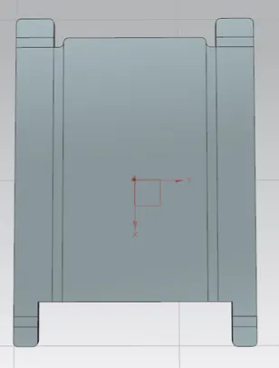
- From Feature option -->Select holes to create hole. Location are at the four corner on the flanges of radius 5mm and 8mm away from both the adjacent edges
- Sketch -->draw lines at the flanges and add point + on one flange and use mirror option to create other holes.
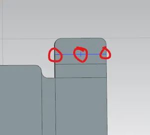
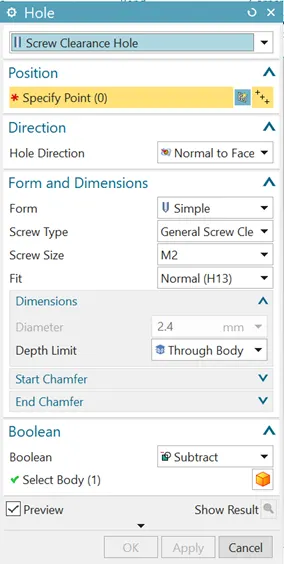
- Features -->use hole -->select screw clearance type select the points, screw type is M2 and Fit is Normal H13 and the depth is through the body
- Create the below drawing at the center plate plane. Sketch -->Polygon with sides of 5mm from the centers
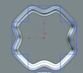
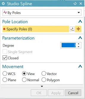
- Sketch -->Studio Splines select by poles and use the Degree -->closed and Movement -->View. Pole locations are 16 poles
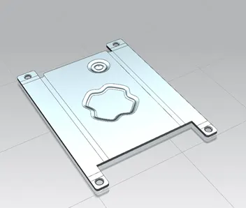
- Punch-->Dimple option to create a dimple about the sketch
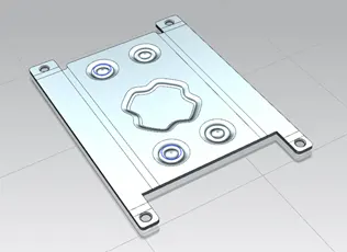
- Punch -->Dimple -->Create Sketch, create circle of 5mm Radii 8mm from adjacent edges. As shown use Feature -->Mirror to mirror the circle and the dimple. On rest areas as shown
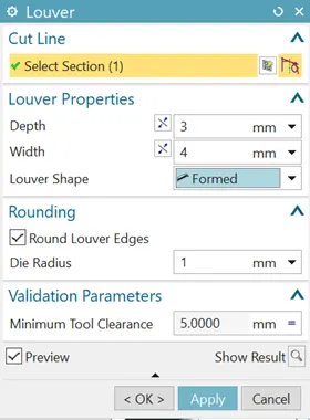
- Punch -->Louver use sketch and create a 10mm horizontal line, louver properties depth 3mm and width 4mm and rounding edges 1mm
- Form -->Unbend option -->select base plate and rest of them to unbend the features
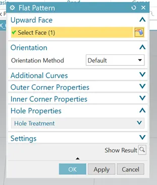
- Flat pattern -->select Flat pattern -->select OK
- Application -->Drafting option -->Home -->Name of the file and create base views
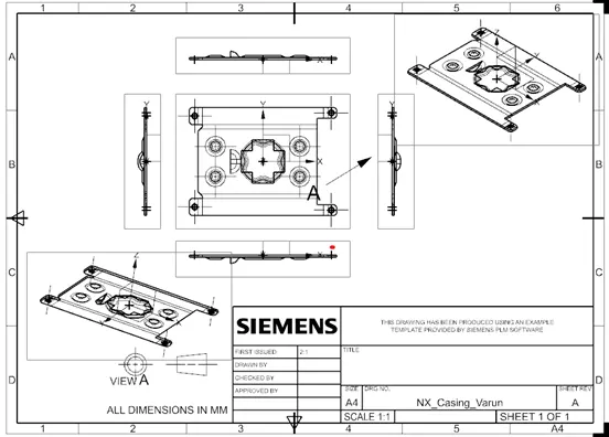
- Open NX CAD --> open a new model from the selection
- Differenet View --> Isometric View:
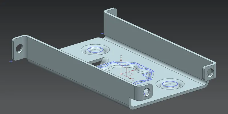 Front View:
 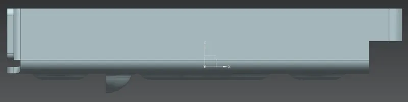 Side view: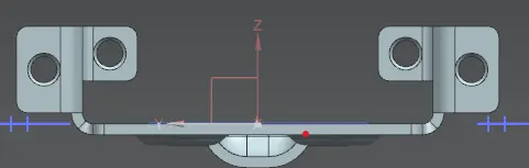
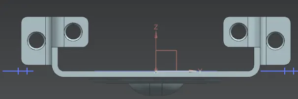 Top view and Bottom view: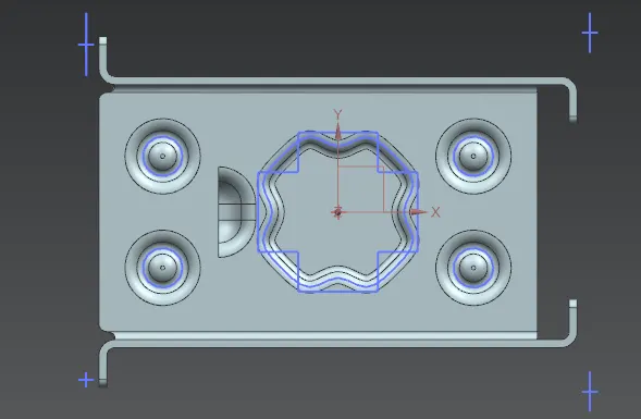
- Conclusion: The Part is created and all the drafting work is submitted