Week 3 - 2D meshing for sheet metal
Aim: Execute Proper Mid surfacing, Good Mesh Flow, No OFF elements, Thickness Assignment to the given model.
Procedure:
Topology:
1st Step:
Load the CAD geometry into ANSA
2nd Step:
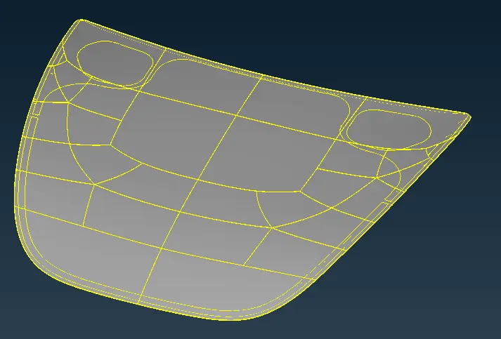
Check for the orientation of the faces make them homogenous.
Before orienting:
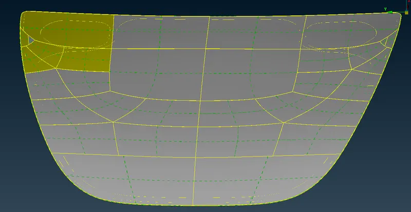
After orientating
3rd step:
Check for the geometry using the check geometry option.
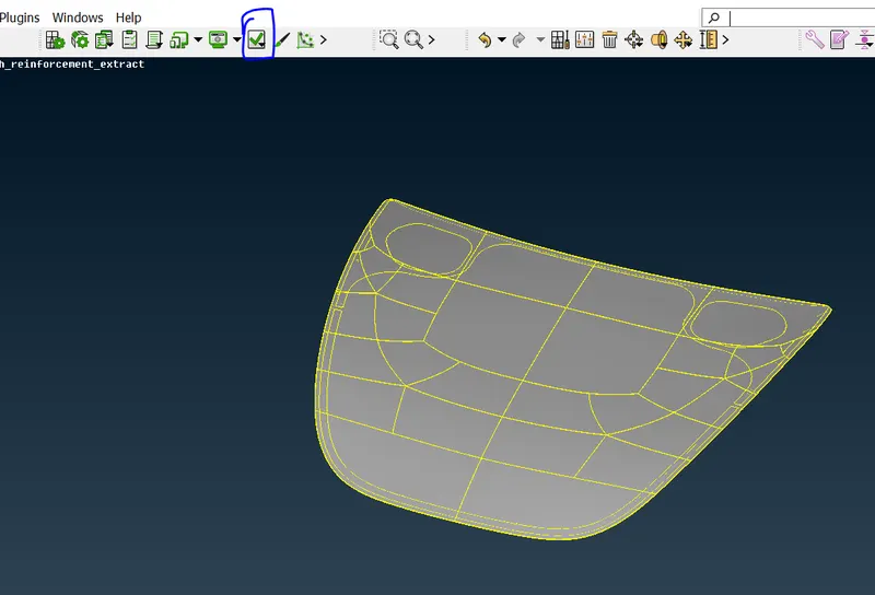
The upper surface has no error or defects.
the lower surface or Reinforcement is having few errors as shown in the fig below
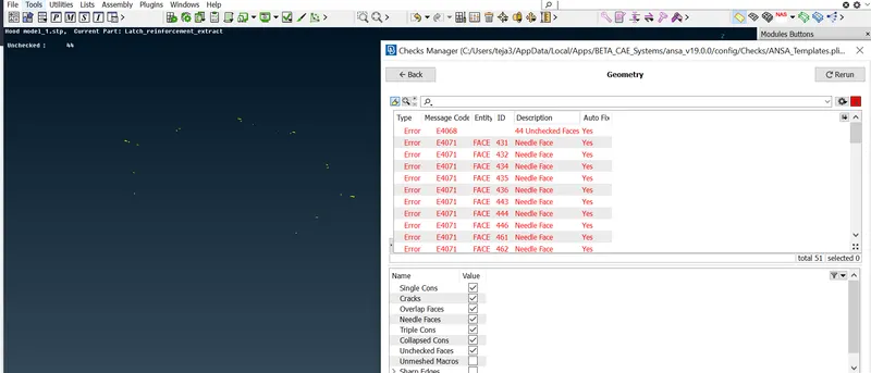
Using the auto fix to fix the errors or using manual process by deleting the needle faces.
4th Step:
Create lock views for the ease of operations
i) Sheet metal Surface
ii)Reinforcement
iii) Latch location
5th Step:
Assign material ID to properities ID's
6th Step:
Measure the thickness of the sheet metal Surface.
7th Step:
Use Face offset to create the Mid Surfaces for Individual Surfaces as shown in image
Metal Hood top surface- Midsurface:
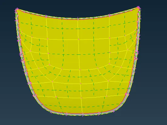
Reinforcement Midsurface:
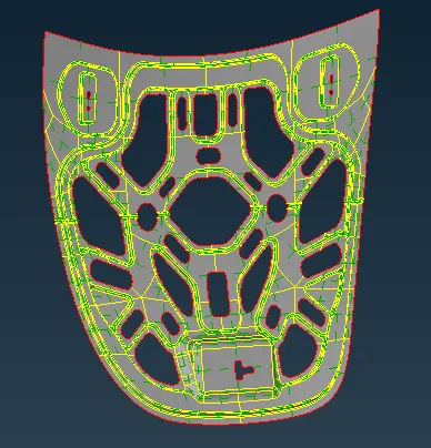
Latch location-Midsurface:
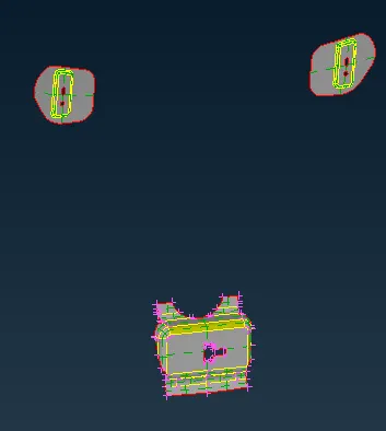
8th Step:
Check for geometry issues and corrections.(Similar to 3rd Step)
9th Step:
Assign poperties IDs to each Mid-surface with respect to thickness variation.
10th Step:
Starting with the Hood top surface, assign perimter length as 5mm
Meshing:
1st Step:
Top Hood surface:
- Input the quality requirement criteria in the mesh quality menu as shown in the image
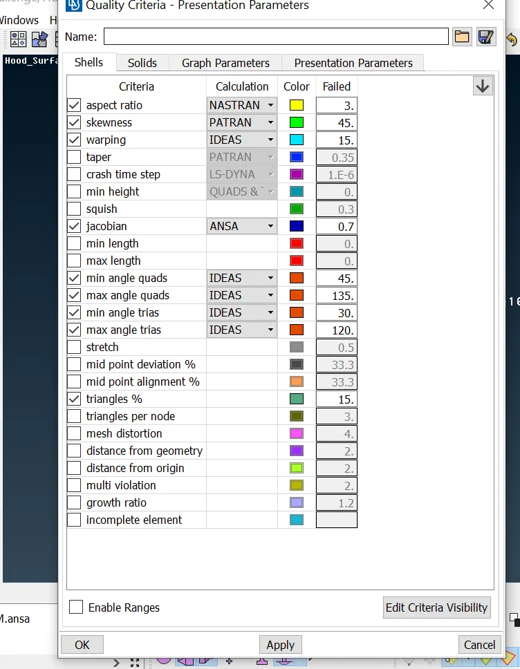
- Created small regions using cut or project cut features.
- Using Swap, Split options to moved the trias away from the perimeters
- Using element offset options to create a copy of the FE's and using transform option to move the FE's to the symmetric location using the Symmetry 3-point option.
- At the curved underbody location used steps similar (the Best mesh) to create mesh all around and moved the trias away from the perimeter
- Used Mesh Release option to release and create a FE model seperate from geometry
Reinforcement Midsurface:
- Similar to the Top Hood surface created mesh for Reinforcement Mid-surface geometry.
Latch location-Midsurface:
- Similar to the Top Hood and Reinforcement surface created mesh for latch location Mid-surface geometry.
RELEASING THE MESH FROM THE CAD GEOMETRY HAS BEEN ACCOMPLISHED.
LESSONS LEARNED:
1. The edges or the fillet location at the beeding has to be converted to simple geometry using Macros Join option.
2. Dividing the surface into the smaller section would help get better meshing than whole surface.
3. Hybrid button help to finish the work faster and efficently with out dealy at switching between buttons.
4. Cons at the fillet regions are easy way to create elements with required quality criteria.
Conclusion:
The FEM Finite Element model is generated and released from the goemetry.
The finished model is attached below.